J. Eberhardsteiner et.al. (eds.) Vienna, Austria, September 10-14, 2012
CONFORMING FINITE ELEMENTS WITH EMBEDDED STRONG
DISCONTINUITIES
D. Dias-da-Costa1,*, J. Alfaiate2, L.J. Sluys3, P. Areias4, C. Fernandes1, E. Júlio2
1
INESC Coimbra, Department of Civil Engineering, University of Coimbra Rua Luís Reis Santos, 3030-788 Coimbra, Portugal
e-mail: [email protected]; [email protected]
2
ICIST, Dep. of Civil Eng., Instituto Superior Técnico, Technical University of Lisbon Av. Rovisco Pais 1, 1049-001 Lisboa, Portugal
e-mail: [email protected]; [email protected]
3
Delft University of Technology, Department of Civil Engineering and Geosciences P.O. Box 5048, 2600 GA Delft, The Netherlands
e-mail: [email protected]
4
ICIST, Physics Department, University of Évora
Colégio Luís António Verney, Rua Romão Ramalho 59, 7002-554 Évora, Portugal e-mail: [email protected]
Keywords: Strong embedded approach; Discrete cracking; Conforming; Non-homogeneous jumps
Abstract. The possibility of embedding strong discontinuities into finite elements allowed the
simulation of different problems, namely, brickwork masonry fracture, dynamic fracture, fail-ure in finite strain problems and simulation of reinforcement concrete members. However, despite the significant contributions to this field, a general embedded formulation capable of dealing with strong discontinuities using conforming finite elements is still missing. Therefore a new conforming embedded formulation is herein proposed and compared with other rele-vant formulations, namely the Generalised Strong Discontinuity Approach (GSDA) [1] and the Generalised/Extended Finite Element Method (GFEM/XFEM) [2-5]. Academic and struc-tural examples are given in order to illustrate the capabilities of the proposed approach in comparison with GSDA and GFEM/XFEM. In summary, the proposed formulation has the following properties: i) variational consistency; ii) no limitations on the choice of the parent finite element; iii) comprehensive kinematics of the discontinuity, including both rigid body motion and stretching; iv) fully compatible enhanced kinematic field; v) additional degrees of freedom located at the discontinuity; vi) continuity of both jumps and tractions across element boundaries; and vii) stress locking free.
1 INTRODUCTION
The embedment of discontinuities into finite elements is a powerful technique for the simulation of fracture in a wide variety of mechanical problems. The first formulations were developed within the Enhanced Assumed Strain method framework (EAS) [6]. Typically con-stant jumps are embedded using Concon-stant Strain Triangles (CST) and full advantage of the static condensation of the additional degrees of freedom is adopted [6-14]. However: i) no in-terelement continuity requirement is imposed on the enhanced strain field; and, as a conse-quence, ii) no traction continuity across element boundaries is obtained.
Bolzon [15] presented an innovative formulation with conforming elements to capture the rigid body opening of the discontinuity. For that purpose the additional degrees of freedom are: i) placed at the edges of the enriched element; and ii) defined at global level to enforce traction continuity across elements. The major drawback remains the fact that only CST ele-ments can be adopted. Moreover, only very simple structural examples have been presented.
Alfaiate et al. [16] introduced an approach for embedding interface elements into any par-ent elempar-ent, capturing linear jumps along the discontinuity. This formulation was developed within the framework of the discrete crack approach and the additional degrees of freedom were introduced as global to ensure traction continuity across element edges. Dias-da-Costa et al. [17] provided a variationally consistent formulation handling rigid body jump transmission induced by the opening of the discontinuity. In the latter approach, the discontinuity is mod-elled as an internal interface of the element.
Linder and Armero [18] developed a general framework to embed both rigid and stretching opening modes of the discontinuity into any parent element. Since the authors took advantage of the static condensation, traction continuity is not obtained. A variationally consistent for-mulation with traction continuity was introduced by Dias-da-Costa et al. [1], called the Gen-eralised Strong Discontinuity Approach (GSDA). The GSDA considers the rigid body motion and stretching of over , the domains at the both sides of the discontinuity. However, although jumps and tractions remain continuous across element boundaries, no interelement continuity of the enhanced displacement field is achieved in the GSDA.
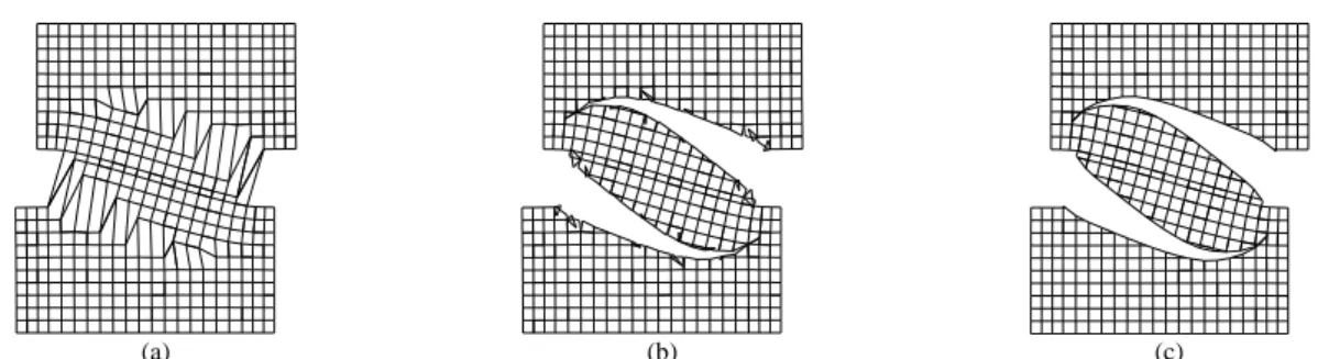
Despite the above mentioned relevant contributions to this field, a general embedded for-mulation capable of dealing with strong discontinuities using conforming finite elements is still missing. Figure 1 is used to illustrate what occurs with a typical deformed mesh where displacements are magnified 200 times:
i) in Figure 1a the usual representation is shown, where only the regular nodes of each el-ement are represented. Therefore, the enriched elel-ements remain unpartitioned and seem com-patible, although distorted;
ii) Figure 1b corresponds to Figure 1a, but now each enriched element has the discontinui-ty truly represented inside the parent element and the corresponding domain becomes parti-tioned. Therefore, the non-conformity of the elements becomes evident;
iii) in Figure 1c the expected deformed mesh obtained with a fully conforming formulation is shown.
A a new general conforming embedded formulation is proposed here aiming to fulfil the following main objectives: i) variational consistency; ii) comprehensive kinematics of the dis-continuity including both rigid body motion and stretching; iii) no limitation on the choice of the parent finite element; iv) additional degrees of freedom located at the discontinuity; v) continuity of both the jumps and the tractions across element boundaries by using global addi-tional degrees of freedom; vi) fully compatible displacement field; and vii) stress locking free.
(a) (b) (c) Figure 1: Deformed mesh obtained using embedded elements (displacements magnified 200 times): (a) classic
representation of (apparently compatible) deformed elements; (b) representation of the true deformed mesh re-vealing non-conforming elements; (c) solution with conforming elements.
2 KINEMATICS AND VARIATIONAL FORMULATION OF A STRONG DISCONTINUITY
Consider an elastic domain with an external boundary and an internal boundary, which is the discontinuity , dividing the domain in two subregions: d and (see Fig- ure 2) subjected to: i) quasi-static loading body forces b ; ii) natural boundary conditions t distributed on the external boundary ; and iii) essential boundary conditions u prescribed t
at the boundary . The vector n is orthogonal to the boundary surface, pointing outwards, u
whilst n is orthogonal to the discontinuity and pointing inwards .
ˆ u n+ Γd Γu Ω− Ω+ n ¯ t Γ Γt [[u]] ˜ u|Γd= [[u]] ˆ u + ˜u
Figure 2: Domain crossed by a strong discontinuity d and 1-D representation of displacement.
The total displacement u is composed by the sum of two parts: i) the regular displacement field uˆ; and ii) the enhanced displacement field u, induced by the jumps at the discontinuity:
ˆ ( ) ( ) ( ) d u x u x u x , (1) where d
is the standard Heaviside function.
The jump at the discontinuity is obtained by evaluating the enhanced displacement field along the discontinuity:
| | d d u u u u . (2)For small displacements, the strain field is:
s s s ˆ in , d d s ε u u u u n (3)where (·)s is the symmetric part of (·) and is the dyadic product.
For the problem under consideration, the principle of virtual work can be written as [1, 19]:
s ( ) : ( ) · · · 0 d d d t d d d d
u σ ε
u t
u b
u t . (4) 3 ELEMENT TECHNOLOGYIn this section the general framework for obtaining conforming enriched elements, namely the jump transmission technique, the discretised equations and the crack propagation issues are presented.
3.1 Element interpolation
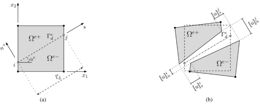
Consider a finite element partition of a 2D domain. Each enriched finite element , with e n nodes, is crossed by a straight discontinuity dividing it in two subdomains. The adopted ed conventions are represented in Figure 3.
le d Γed s x2 x1 n+ Ωe+ Ωe− αe i j [[u]] j n [[u]] j s [[u]] i s Ωe− Ωe+ [[u]]in Γe d (a) (b) Figure 3: Domain e crossed by a strong discontinuity ed: (a) definitions; and (b) general opening.
The following equation provide the approximation of the displacement field for each en-riched finite element:
( ) if , d d e e e e e e e d u N x a I H a x (5)
e e e e( ) e at ,e d u u u N x a (6)where N contains the element shape functions, e a are the total nodal degrees of freedom re-e lated to u , e a are the enhanced nodal degrees of freedom related to e u , e
d
e
H is a
2n2n
diagonal matrix with components equal to ‘1’ for nodal degrees of freedom in and ‘e0’ otherwise.
In order to capture the kinematics of the discontinuity regarding both rigid body motion and stretching of over , two additional nodes are placed at the edges of each enriched element (see Figure 3). Therefore, the enhanced nodal degrees of freedom become:
, e ek e w a M w (7)
where w is a vector formed by juxtaposing by rows the additional degrees of freedom re-e*
ii) all remaining enriched elements sharing at least one node with element ‘e’. Matrix M ekw* has also the contribution of all these enriched elements, such that each row, M is in direct eiw correspondence to the i -node of the element ‘e’ and can be computed by:
* 1, , el n ei e j e j w w w w j j e
M M M M β (8) where M is: ew , w w e e e w R nR M M M (9) with 2 2 2 2 2 2 2 2 1 1 1 1 1 1 1 1( )sin ( ) cos ( )sin ( ) cos
1
,
( )sin ( ) cos ( )sin ( ) cos
1 w i e i e i e i e e e e e d d d d e R i e i e i e i e e e e e d d d d x x x x x x x x l l l l x x x x x x x x l l l l M (10)
1 cos(2 ) sin(2 ) 1 cos(2 ) sin(2 )
2 2 2 2
sin(2 ) 1 cos(2 ) sin(2 ) 1 cos(2 )
2 2 2 2 w e e e e e e e e n n n n e nR e e e e e e e e n n n n s s s s s s s s M (11) and 1 1 2 2 ( ) cos( ) sin( ) ( ) ( ) , e e e i i i n e e e d d d s s x x x x l l l x (12)
where x
x x1, 2
is the global position of any material point inside the finite element,
1, 2
i i i
x x
x is the global position of the tip ‘i ’ (Figure 3a), l is the length of the discontinui-de
ty measured along the local frame ed s and ‘e’ is the discontinuity angle defined in Figure 3a.
It is stressed that w
e R
M is the rigid-body part, which includes both normal and constant shear jump components, and
w
e nR
M is the non-rigid stretching part along the discontinuity ed (see [1]).
j
β is a diagonal matrix computed at each node ‘ j ’, containing
i
j x
terms for both direc-tions
x x1, 2
, representing a measure of the relative stiffness contribution of each enriched element for the enhanced displacement field:, , 1 , i i el i j i x j x n k i x k K K
(13)where , i
j i x
K is the stiffness matrix component of the bulk for element ‘ j ’ for direction x (see i Figure 3a). Therefore, a mutual dependence between jumps and bulk deformation is built, leading to a fully compatible formulation.
The strain field is approximated using the standard strain-displacement matrix, B : e
( ) in d d e e e e ek e e e w d ε B x a I H M w . (14)The incremental stress field and incremental traction at the discontinuity are given by:
* * ( ) in \ d d e e e e e ek e e e w d d dσ D B x da I H M w , (15) and
* * ( ) at , e e e e e ek e e w d dt T d u T N x M w (16)where D and e T are, respectively, the bulk and the discontinuity constitutive matrices. e
3.2 Discretised equations
Equation (4) is discretised using Equations (5) to (16) and by progressively taking: i) dwe 0 ; and ii) dae0 , the following system of equations is obtained:
ˆ , e e e e e aad awd d K a K w f (17)
e e e e e e wad ww d d d w K a K K w f (18) where: \ , e e d e eT e e e aa
d K B D B e\ e , d e eT e e e aw
wd K B D B e\ e , d e eT e e e wa
w d K B D B \ , e e d e eT e e e ww
w wd K B D B e , d e e T e e e d
w wd K N T N
* , d d e e e ek w w B B I H M
* , d d e e e ek w w N N I H M \ ˆ e e e d t e eT e e eT e d d d
f N b N t and \ . e e e d t e eT e e eT e w w w d d d
f N b N tSince traction continuity is enforced in the weak sense, the symmetry of the system of equations is kept if symmetric constitutive matrices are adopted.
3.3 Crack propagation
It is assumed that the discontinuity is straight and crosses an entire parent element and, therefore, the crack tip is always located at the element edge. Only one crack is allowed to exist inside each enriched element. Furthermore, each new embedded discontinuity can only be inserted: i) at the crack tip; or ii) at a new element if outside the neighbourhood of existing crack tips (provided by a radius of influence centred at each crack tip with a value of three to five times the maximum aggregate size).
Crack path continuity is enforced using the algorithm presented in [20], whereas the direc-tion of propagadirec-tion is provided using a Rankine criterion, according to which cracking occurs perpendicularly to the direction of maximum tensile stress.
4 EXAMPLES
In this section both element and structural examples of the presented formulation are pre-sented. All examples are computed using bilinear plane stress elements. Both GSDA [1] and GFEM/XFEM [5, 21] are adopted for comparison purposes.
The element examples of Sections 4.1 and 4.2 have been chosen to illustrate the kinematics of the proposed embedded formulation. In Section 4.1 two neighbouring elements with differ-ent stiffness are enriched, whereas in Section 4.2 a small example is used to illustrate the compatibility issues at the tip of a crack front.
Finally, in Section 4.3 a double-edged-notched specimen subjected to mixed-mode frac-ture [22] is presented.
4.1 Two enriched elements
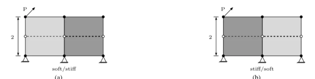
Consider two enriched elements, each one with dimensions 2 2 1 mm 3, according to the models represented in Figure 4. In the first model, see Figure 4a, the left element is softer than the right element, whereas the opposite is assumed for the second model (see Figure 4b). In both cases the right discontinuity is stiffer than the left discontinuity.
Linear elastic relationships are adopted for both the bulk and the discontinuity. The materi-al parameters for the bulk are the following: Young's modulus E10 N/mm2 and Poisson ratio 0 for the softer bulk element; Young's modulus E and Poisson ratio 0 for the stiffer bulk element. The discontinuity constitutive matrix (see Equation (16)) has the di-agonal components related to the normal and shear stiffness equal to: kn ks 1N/mm3 for the left discontinuity; and kn ks for the right discontinuity.
2 P soft/stiff stiff/soft P 2 (a) (b) Figure 4: Mesh and loading conditions (dashed line indicates the prescribed discontinuity): (a) first element soft
and second element stiff; (b) first element stiff and second element soft.
The resulting deformed mesh for P(1;1) N is represented in Figures 5 and 6 for both cases. It can be concluded that: i) although the GSDA is able to enforce continuous jumps and tractions across elements (see the closed tip between the elements in Figures 5a and 6a), a ‘gap’ appears between the elements due to the non-conforming enrichment; ii) a conforming enrichment is obtained with the new embedded formulation which is able to adequately re-produce the kinematics of the discontinuity (similar conclusion regarding GFEM/XFEM); and iii) less degrees of freedom are required in the new formulation when compared with GFEM/XFEM; consequently, the bulk is discretised with a smaller number of degrees of freedom and this is noticed in particular for the stiff/softer case where the softer element is loaded (compare displacements obtained with both formulations in Figures 5b and 6b).
(a) (b) Figure 5: Deformed mesh for soft/stiffer case obtained with: (a) the GSDA; (b) the new formulation
(continu-ous) and GFEM/XFEM (dashed).
(a) (b) Figure 6: Deformed mesh for stiff/softer case obtained with: (a) the GSDA; (b) the new formulation
(continu-ous) and GFEM/XFEM (dashed).
4.2 Element in front of the tip
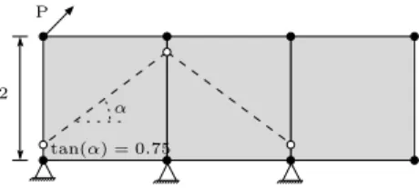
The example presented in this section was selected to show the conforming issues appear-ing due to crack propagation. Three 2 2 1 mm 3 finite elements are considered, where the two elements crossed by a discontinuity are enriched (see Figure 7).
α
P
2
tan(α) = 0.75
Figure 7: Mesh and loading conditions (dashed line indicates the prescribed discontinuity).
Linear elastic properties are considered for both bulk and discontinuity with the following values: Young's modulus E10 N/mm2; Poisson ratio 0; normal and shear stiffness
3
1N/mm
n s
k k . The resulting deformed mesh is represented in Figure 8, for P(1;1) N, from which it can be concluded that: i) although with the GSDA both the jumps and the trac-tions are continuous across element boundaries, incompatible displacements between ele-ments and at the tip are obtained (see Figure 8a); ii) the deformed mesh obtained with the new formulation and GFEM/XFEM are qualitatively better; iii) the new embedded approach is ful-ly compatible (see Figure 8b); iv) the displacements obtained with both the new formulation and GFEM/XFEM are similar, although the former leads to a slightly stiffer solution than the latter (see Figure 8b).
(a) (b) Figure 8: Deformed mesh (displacements magnified 2 times) obtained with: (a) the GSDA; (b) the new
formula-tion (continuous) and GFEM/XFEM (dashed).
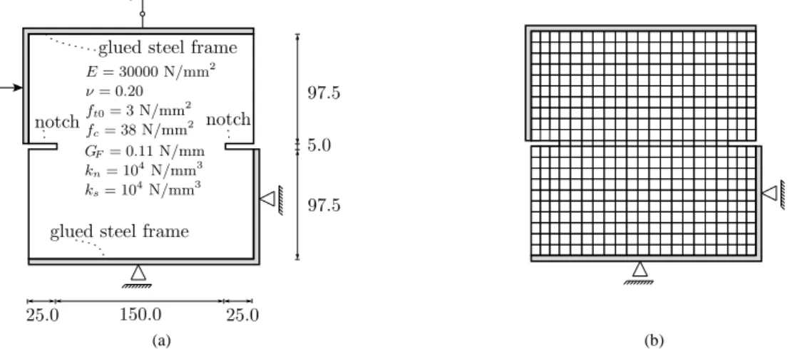
4.3 Nooru Mohamed’s Test
This example consists of a double-edged-notched specimen subjected to mixed-mode frac-ture, experimentally tested by [22]. The 200 200 50 mm 3 specimen has two 25 5 mm 2 horizontal notches located at half height. The specimen is loaded by means of two L-shaped steel frames glued to the specimen. One of the experimental load paths is numerically simu-lated: i) a horizontal force P is applied and increased to 10 N , after which it is kept constant; 4 and ii) a vertical displacement u is gradually enforced into the top steel frame (Figure 9a). v
fc= 38 N/mm2 E = 30000 N/mm2 notch ks= 104N/mm3 kn= 104N/mm3 GF= 0.11 N/mm
glued steel frame
97.5 97.5 5.0 25.0 25.0 150.0 P
glued steel frame
notch
uv
ft0= 3 N/mm2
ν = 0.20
(a) (b) Figure 9: Nooru Mohamed's test: (a) structural scheme (50 mm width, dimensions in mm); and (b) adopted
mesh with 435 bilinear elements.
The material parameters are taken from [22]: Poisson ratio 0.2; Young's modulus
2
30000 N/mm
E ; compressive strength fc 38 N/mm2, tensile strength ft0 3.0 N/mm2; and fracture energy GF 0.11N/mm. The initial normal and shear stiffness adopted for the
discontinuity is 4 3
10 N/mm
n s
k k . Upon crack opening, the constitutive law by [20] is
adopted, with ft0/c0 0.6, where c is the cohesion estimated using Mohr's rupture the-0 ory.
The adopted mesh with 435 bilinear finite elements is represented in Figure 9b. The arc-length method is used to enforce a monotonic increase of the vertical displacement of the top steel frame (u ). The discontinuities are inserted from the notch. v
All results are shown in Figures 10 to 12, including the vertical displacement vs. load curves, the crack path, the deformed mesh and the map of the first principal stress. It must be stressed that the experimental peak load is smaller than the corresponding numerical values, which is also verified by other authors [23-25].
GFEM/XFEM 4.5 9 13.5 18 0 0.05 0.1 0.15 0.2 Load (kN) Vertical displacement, uv(mm) Experimental New approach GSDA 0 Experimental New approach GFEM/XFEM GSDA (a) (b) Figure 10: Nooru Mohamed's test: (a) vertical displacement vs. load curves; and (b) crack path computed at
0.2mm v
u .
From the numerical results it can be observed that the conforming formulations (GFEM/XFEM and the new embedded approach), provide similar displacement vs. load curves, crack paths and deformed meshes. Furthermore, the stress map represented in Figure 12 reveals that the new embedded formulation adequately reproduces the stress field in the bulk, with stresses gradually approaching zero in the vicinity of the crack.
(a) (b) Figure 11: Nooru Mohamed's test - deformed mesh (displacements magnified 150 times) for uv0.2 mm
ob-tained with: (a) the GSDA; and (b) the new formulation.
5 CONCLUSIONS
A new formulation using conforming finite elements with embedded strong discontinuities was presented. Compared to previous embedded approaches, namely [1, 9, 10, 16-18, 26, 27]: i) no additional degrees of freedom are required; and ii) the continuity of both tractions and enhanced kinematical field across elements is automatically ensured. The proposed formula-tion is variaformula-tionally consistent and built upon the framework of the discrete crack approach. Therefore, mesh objectivity is automatically inherited.
From the presented examples it is concluded that the new embedded formulation is capable of providing results which are practically indistinguishable from the results obtained with GFEM/XFEM.
3.0 2.2 1.5 1.0 0.6 0.2 0.1 0.0 σ1 3.0 2.2 1.5 1.0 0.6 0.2 0.1 0.0 σ1 (a) (b) Figure 12: Nooru Mohamed's test - principal stress (displacements magnified 150 times) for 1 uv0.2 mm
obtained with: (a) the GSDA; and (b) the new formulation.
However, in spite of the common variational framework [21] and similar results, the two formulations are built in a significantly different manner. The following main differences can be advanced:
the GFEM/XFEM is nodal based whereas the present formulation is built at ele-ment level;
crack propagation is simpler to implement in the embedded approach, since only the crossed finite elements are enriched, instead of all nodes surrounding the dis-continuity, as typically performed in GFEM/XFEM;
with the embedded formulation, only one additional node is required at each new enriched finite element due to crack propagation, whereas with GFEM/XFEM all nodes supporting the discontinuity must be enriched;
with the present formulation, all additional degrees of freedom are located at the discontinuity, where the quantities of interest are measured.
Finally, although the observed computational cost was similar for the bi-dimensional struc-tural problems above presented, the embedded formulation is expected to gain advantage in three-dimensional problems since significantly fewer degrees of freedom are required for each enriched finite element.
6 ACKNOWLEDGMENTS
This work is supported by FEDER funds through the Operational Programme for Competitiveness Factors – COMPETE – and by Portuguese funds through FCT – Portuguese Foundation for Science and Technology under Project No. FCOMP-01-0124-FEDER-020275 (FCT ref. PTDC/ECM/119214/2010).
REFERENCES
[1] D. Dias-da-Costa, J. Alfaiate, L.J. Sluys, E.N.B.S. Júlio: Towards a generalization of a discrete strong discontinuity approach, Computer Methods in Applied Mechanics and Engineering, 198 (2009) 3670-3681.
[2] C.A.M. Duarte, J.T. Oden: H-p clouds - a meshless method to solve boundary-value problems, in, TICAM, University of Texas at Austin, 1995.
[3] T. Belytschko, T. Black: Elastic crack growth in finite elements with minimal remeshing, International Journal for Numerical Methods in Engineering, 45 (1999) 601-620.
[4] A. Simone: Partition of unity-based discontinuous elements for interface phenomena: Computational issues, Communications in Numerical Methods in Engineering, 20 (2004) 465-478.
[5] G.N. Wells, L.J. Sluys: A new method for modelling cohesive cracks using finite elements, International Journal for Numerical Methods in Engineering, 50 (2001) 2667-2682.
[6] J.C. Simo, M.S. Rifai: A class of mixed assumed strain methods and the method of incompatible modes, International Journal for Numerical Methods in Engineering, 29 (1990) 1595-1638.
[7] J.C. Simo, J. Oliver, F. Armero: An analysis of strong discontinuities induced by strain-softening in rate-independent inelastic solids, Computational Mechanics, 12 (1993) 277-296.
[8] R. Larsson, K. Runesson: Element-embedded localization band based on regularized displacement discontinuity, Journal of Engineering Mechanics, 122 (1996) 402-411. [9] J. Oliver: Modelling strong discontinuities in solid mechanics via strain softening
constitutive equations. Part 1: Fundamentals, International Journal for Numerical Methods in Engineering, 39 (1996) 3575-3600.
[10] J. Oliver: Modelling strong discontinuities in solid mechanics via strain softening constitutive equations. Part 2: Numerical simulation, International Journal for Numerical Methods in Engineering, 39 (1996) 3601-3623.
[11] U. Ohlsson, T. Olofsson: Mixed-mode fracture and anchor bolts in concrete analysis with inner softening bands, Journal of Engineering Mechanics, 123 (1997) 1027-1033. [12] M. Jirásek, T. Zimmermann: Embedded crack model: Part I. Basic formulation,
International Journal for Numerical Methods in Engineering, 50 (2001) 1269-1290. [13] M. Jirásek, T. Zimmermann: Embedded crack model: Part II. Combination with
smeared cracks, International Journal for Numerical Methods in Engineering, 50 (2001) 1291-1305.
[14] R.I. Borja: A finite element model for strain localization analysis of strongly discontinuous fields based on standard Galerkin approximation, Computer Methods in Applied Mechanics and Engineering, 190 (2000) 1529-1549.
[15] G. Bolzon: Formulation of a triangular finite element with an embedded interface via isoparametric mapping, Computational Mechanics, 27 (2001) 463-473.
[16] J. Alfaiate, A. Simone, L.J. Sluys: Non-homogeneous displacement jumps in strong embedded discontinuities, International Journal of Solids and Structures, 40 (2003) 5799-5817.
[17] D. Dias-da-Costa, J. Alfaiate, L.J. Sluys, E.N.B.S. Júlio: A discrete strong discontinuity approach, Engineering Fracture Mechanics, 76 (2009) 1176-1201.
[18] C. Linder, F. Armero: Finite elements with embedded strong discontinuities for the modeling of failure in solids, International Journal for Numerical Methods in Engineering, 72 (2007) 1391-1433.
[19] L.E. Malvern: Introduction to the mechanics of a continuous medium. Prentice-Hall International, Englewood Cliffs, New Jersey, 1969.
[20] J. Alfaiate, G.N. Wells, L.J. Sluys: On the use of embedded discontinuity elements with crack path continuity for mode-I and mixed-mode fracture, Engineering Fracture Mechanics, 69 (2002) 661-686.
[21] D. Dias-da-Costa, J. Alfaiate, L.J. Sluys, E.N.B.S. Júlio: A comparative study on the modelling of discontinuous fracture by means of enriched nodal and element techniques and interface elements, International Journal of Fracture, 161 (2010) 97-119.
[22] M.B. Nooru-Mohamed: Mixed-mode fracture of concrete: an experimental approach, in, Delft University of Technology, Delft, the Netherlands, 1992, pp. 151.
[23] P. Pivonka, J. Ozbolt, R. Lackner, H.A. Mang: Comparative studies of 3D-constitutive models for concrete: application to mixed-mode fracture, International Journal for Numerical Methods in Engineering, 60 (2004) 549-570.
[24] M. Cervera, M. Chiumenti: Smeared crack approach: back to the original track, International Journal for Numerical and Analytical Methods in Geomechanics, 30 (2006) 1173-1199.
[25] T.C. Gasser, G.A. Holzapfel: 3D Crack propagation in unreinforced concrete: A two-step algorithm for tracking 3D crack paths, Computer Methods in Applied Mechanics and Engineering, 195 (2006) 5198-5219.
[26] J. Oliver, M. Cervera, O. Manzoli: Strong discontinuities and continuum plasticity models: The strong discontinuity approach, International Journal of Plasticity, 15 (1999) 319-351.
[27] J. Oliver: Contributions to the continuum modelling of strong discontinuities in two-dimensional solids, in, Centro Internacional de Métodos Numéricos en Ingeniería, Barcelona, 2003, pp. 172.