Cylindrical Grinding Processes Using a Conventional Wheel
*e-mail: [email protected], [email protected]
Analysis of the Influence of Infeed Rate and Cutting Fluid on
Cylindrical Grinding Processes Using a Conventional Wheel
Eduardo Carlos Bianchia*, Carolina Grimm Franzob, Paulo Roberto de Aguiarb, Rodrigo Eduardo Cataic*
aDepartment of Mechanical Engineering, UNESP
São Paulo State University, Bauru - SP, Brazil bDepartment of Electrical Engineering, UNESP
São Paulo State University, Bauru - SP, Brazil cDepartment of Materials and Technology, UNESP
Guaratinguetá - SP, Brazil
Received: June 24, 2003; Revised: April 5, 2004
New worldwide trends such as globalization have rendered grinding processes increasingly important for industry, making it essential to perform in-depth studies of variations in grinding process parameters in the pursuit of greater cost effectiveness. This paper presents a comparative analysis of three different infeed rates, using a conventional grinding wheel on quenched and tempered D2 steel workpieces. Higher infeed rates are known to be correlated with shorter grind-ing times, rendergrind-ing the process more economically attractive. Two different coolant fluids, 5% emulsion and pure oil, were used. The tests were carried out using the smallest possible amount of coolant and an optimized 5 mm diameter nozzle. The parameters analyzed were tangential force, specific energy, acoustic emission, roundness error and surface roughness. The surfaces of the workpieces were also examined by scanning electron microscopy (SEM). The results revealed that increased infeed rates could reduce processing times without compromising the quality of the workpiece profile, thereby reducing the cost of the process. The best cutting fluid, albeit more harmful to human health and less environmentally friendly, was found to be pure oil.
Keywords: Cylindrical Plunge Grinding, Infeed Rate, Cutting Fluid, SEM and Roundness Error
1. Introduction
Grinding is considered one of the most important proc-esses in manufacturing today due to its high accuracy. The loss of a single piece is unacceptable in this stage of the production process, when the material’s added value is al-ready high because of the many processes that have pre-ceded the grinding operation (Oliveira, 1989).
According to Malkin (1989), 20 to 25% of manufactur-ing costs are incurred in the grindmanufactur-ing process. Knapp (1999) states that vibrations between the wheel and the workpiece must be reduced in order to lower grinding costs. However, reducing these vibrations restricts increases in infeed rates in cylindrical plunge grinding.
This paper presents a bibliographical review of cutting fluids, conventional grinding wheels and the effects caused
by variations in the infeed rate on the final piece. The main parameters that will be measured here are the tangential grinding force, specific energy, acoustic emission, round-ness error and superficial roughround-ness. The workpiece sur-faces were also analyzed by scanning electron microscopy (SEM). In short, results, analyses and conclusions regard-ing the variations in the three infeed rates employed in this study are presented to prove that increased infeed rates do not necessarily worsen the quality of the final workpiece.
2. Objectives
was a conventional aluminum oxide (Al2O3) wheel, the cut-ting fluids were a pure oil and a 5% emulsion, and the three different infeed rates were 0.12 mm/min, 0.25 mm/min and 1.00 mm/min. The workpieces were made of quenched and tempered D2 steel. Monitored assays were performed on each workpiece and the online signals of tangential force, specific energy and acoustic emission measurements were recorded. After the experiment, the workpieces were analyzed individually to verify their roughness, roundness error, and superficial problems such as micro-scratches.
We therefore attempted to determine which of the three infeed rates would be the best choice for this grinding proc-ess, and which cutting fluid would offer the greatest cost effectiveness, no wastage, and minimize the processing time without impairing the surface integrity of the workpiece.
3. Cutting Fluids and the Conventional Al
2O
3Grinding Wheel
An essential requirement of good cutting fluids is that they provide proper lubrication, cooling and chip removal. Lubrication decreases the friction between the workpiece and the grinding wheel, reducing the generation of heat and cutting forces, while cooling ensures the workpiece is kept at low temperatures to prevent thermal damage such as cracks. The third task of cutting fluids is to remove the chips generated in the cutting zone, preventing them from enter-ing into contact with the workpiece, which might impair the final smoothness.
According to Baradie (1996), the effective application of cutting fluids can also increase the grinding wheel’s life, improve roughness and dimensional precision and reduce the consumption of energy. Therefore, Motta and Machado’s conclusions (1995) about reduced grinding costs and in-creased production being achieved through the use of ap-propriate cutting fluids are highly justified. The cutting fluid should meet the specific requirements of the grinding process. Minke (1999) states that, in addition to the cooling effect, cutting fluids can lubricate the workpiece, acting decisively to maintain the good quality of the final ground piece. This fact makes cutting fluids one of the most impor-tant parameters in the grinding process. With regard to the characteristics of cutting fluids, pure oil is believed to have a high lubricating capacity while emulsion has a high cool-ing capacity.
According to Webster et al. (1995), a jet of fluid strik-ing squarely upon the cuttstrik-ing region can decrease the re-gion’s temperature considerably; however, high fluid jet ve-locities are required for the fluid to effectively penetrate the cutting region. This fact was confirmed when the fluid ve-locity was equal to the grinding wheel peripheral veve-locity. The use of a rounded nozzle led to a marked decrease in the cutting region temperature when compared with the
con-ventional fluid jet. Webster et al. (1995) also found that the angle of incidence of the jet in the cutting region does not substantially lower the temperature of the workpiece; how-ever, the tool’s peripheral velocity in relation to the fluid jet is very important in the cooling process of the workpiece.
The model proposed by Webster et al. (1995) was em-ployed in this work, since a rounded nozzle tends to mini-mize the internal turbulence produced by the fluid’s pen-etration velocity and the turbulence at the point where the fluid exits the nozzle, which is caused by the presence of sharp edges at this exit point. The proposed model has a hollow surface, decreasing the occurrence of pressure drops and turbulence as the cutting fluid passes through and ex-its the nozzle.
The abrasive wheel grains may be made of either natural or synthetic materials and should usually be harder than the workpieces. The natural abrasive grains include aluminum oxide (natural corundum and emery), grit and diamond. The conventional abrasives are synthetic aluminum oxide or sili-con carbide-based materials, but the main requirement of an abrasive grain is that it should be harder than the material to be ground (Malkin, 1989).
4. Effects of Infeed Rate Variations
Lee & Kim (2001) conducted experiments in which they monitored the electric current of the spindle motor to com-pare the behavior of the wheel’s speed and the infeed rates. Their results indicated that when the wheel speed increases, the spindle motor current decreases, but that when the infeed rates increase, the spindle motor current also increases. The tangential force and specific energy display the same behavior, i.e., they also increase.
According to the above authors, the values of acoustic emission, energy and roughness increase along with the infeed rates.
Hara (1999) has another point of view about the rough-ness according to infeed rate variations, stating that no di-rect correlation exists between roughness and infeed rates, even under severe conditions. The main factor that influ-ences the roughness is the spark-out effect, when there is no infeed rate variation for about 10 s. In other words, the difference in roughness can probably be ascertained before spark-out occurs.
SEM is a useful tool to identify thermal damage such as micro-cracks and other problems that may impair the final quality of the workpiece profile. According to Malkin (1989), the plowing effect, i.e., plastic deformation without the removal of material, which is associated with lateral flow-ing of the material, is visible by SEM. We have therefore used SEM to analyze the plowing effect as a function of increasing infeed rates.
Cylindrical Grinding Processes Using a Conventional Wheel
Biera et al. (1997), the vibrational forces generated by the unstable spindle wheel motor or simply by the wheel itself might explain roundness errors, but these factors do not af-fect the final grinding results. These authors also state that decreasing the infeed rates lowers the roundness error, since they are closely correlated, but that the spark-out effect may minimize or even eliminate it.
5. Methodology
The tests were conducted in an external cylindrical grinder model RUAP 515 H-CNC manufactured by Sul Mecânica, using quenched and tempered D2 steel workpieces with a hardness of approximately 60 HRc. The tangential force, specific energy and acoustic emission were measurements made using Labview 5.0 software to record the data in the database.
The only variable acquired on-line was the grinding tan-gential force, which was recorded as follows: the signal was captured from the machine motor in volts-Amperes (Va), put through a signal conditioner and transformed into Volts (V). It was then sent to the data acquisition A/D board and analyzed by LabView 5.0 data acquisition software, which performed the required computation. The grinding tangential force value (Ftc) was obtained assuming that Pe was the motor electric power, n the grinding wheel rotation and ds outer grinding wheel diameter.
(1)
The grinding specific energy was calculated based on the tangential force, according to Eq. 2, where, u = specific energy, b = grinding width, dw = workpiece diameter, Ftc = tangential cutting force, Vf = infeed rate and Vs = pe-ripheral wheel speed.
(2)
The acoustic emission (AE) was expressed in Volts (rms), and measured with Sensis BM12 equipment, with the acous-tic emission sensor placed near the workpiece fixation. The device sends signals in Volts to the microcomputer. For each experiment, the conventional grinding wheel was dressed with a single diamond tip dresser, with a dressing overlap ratio of Ud = 1, which removed the adhered material from the grinding wheel through diamond dresser impact. The dressing conditions were identical in all the tests.
For each testing condition, one type of fluid (pure oil and 5% emulsion), one conventional aluminum oxide grinding wheel and one of the three infeed rates: 0.12 mm/min, 0.25 mm/min or 1.00 mm/min were employed, and each test
was repeated three times.
Each test consisted of 40 manufacturing cycles (150.1 mm3 of material removed from the workpiece), and
hundreds of grinding force values were acquired by the data acquisition software in each manufacturing cycle. However,
Figure 1. Webster’s nozzle model (Webster et al.1995).
Figure 2. Schematic diagram of experimental set-up.
only the maximum value of each of the 40 grinding cycles, which was equal to a volume of 150.1 mm3 of removed
material, was taken into account to plot the grinding tan-gential force graphs. Based on this procedure, 40 maximum points of tool effort were obtained to generate a graph with a total of 40 points, with each value representing the tool’s maximum force in a given grinding cycle.
The cutting depth (a = 4 mm), grinding width (b = 3 mm), output fluid velocity (Vsf = 30 m/s) and grinding wheel peripheral velocity (Vs = 30 m/s) were kept constant. The tests were performed using a minimum amount of coolant (output fluid velocity equal to that of the grinding wheel) and an optimized 5 mm diameter output fluid nozzle, fol-lowing the model of Webster et al. (1995).
The roughness was measured with a Taylor Hobson model Sultronic 3 + roughness meter. The impurities of the workpieces were carefully removed by washing and drying and several measurements of each workpiece were made. As for G ratio measurements, the tool profile was measured and marked on a SAE1010 steel bar.
A Jeol - JXA - 840A - Electron Probe Microanalyzer was employed for the SEM analysis, using a zoom of 1500 times magnification on the two grinding fluids and on the most critical infeed rates, which reached extreme velocities of 0.12 mm/min and 1.00 mm/min, respectively. The roundness errors were measured in a Taylor Hobson Talyrond 31C equipment. Were taken 6 measurements at different sections of each workpiece.
6. Results and Discussion
It should be noted that each point shown on the graphs represents the arithmetic average of the maximum values obtained for the three repetitions of the tests. Each graph was plotted by polynomial regression to reach the closest approach to the points obtained.
The figures below indicate that the volumes of 9.5 mm3,
37.5 mm3, 84.8 mm3 and 150.1 mm3 of removed material
exactly match 10, 20, 30 and 40 grinding cycles, respec-tively.
6.1. Tangential grinding force
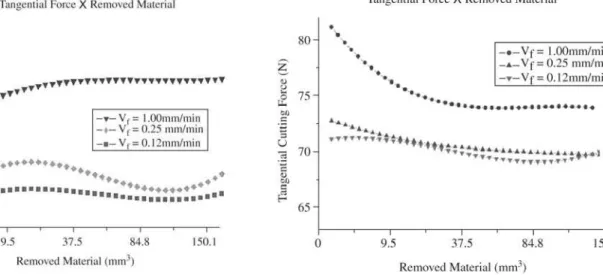
Figure 4a shows the different tangential force values according to the increments in infeed rates, using pure oil as cutting fluid. As can be seen, the highest force exceeds the lowest one by 10% and the intermediate one by 7.9%. The figure also indicates that higher forces are obtained with increases in the infeed rates.
Figure 4b shows that the 5% emulsion cutting fluid be-haved differently, producing a higher tangential force than the pure oil at the beginning of the experiments, after which the tangential force decreased and stabilized.
A comparison of Figs. 4a and 4b reveals that the tool’s efforts were much greater when emulsion was employed.
The lower values obtained for the oil force were due to this fluid’s high lubricating capacity, which made it easier for the grinding wheel to “slide” over the workpiece.
Figure 4a indicates that the cutting force of the pure oil tended to increase due to the prevalence of wear on the grain’s surface. Progressive increases in this wear resulted in a greater contact area between the grinding wheel and the workpiece, thereby increasing the cutting force values. This intensive wear during grinding cycles is caused by the higher fluid lubricating capacity. The tendency for the re-duced cutting force shown in Fig. 4b was also attributed to the grains’ surface wear, which decreased due to the friabil-ity resulting from the emulsion’s lubricating capacfriabil-ity.
6.2. Grinding specific energy
It should be noted that the results of the 0.12 mm/min infeed rate in the tests using pure oil as cutting fluid were not computed, since they showed much higher values than expected. Therefore, no comparisons of the cutting fluids were made at this infeed rate in order to avoid incorrect conclusions.
Figure 5a shows the behavior of the grinding specific energy using pure oil and different infeed rates, while Fig. 5b shows the results for the emulsion. Note that the two cut-ting fluids displayed the same behavior, i.e., the higher the infeed rate the lower the grinding specific energy.
A comparison of Figs. 5a and 5b indicates that, using the 5% emulsion and the same infeed rate, the specific en-ergy values were higher in the initial grinding cycle than in the final cycles, except at an infeed velocity of 0.12 mm/min, when the specific energy values showed an upward curve from the 30th cycle (84.8 mm3) on. The opposite behavior
occurred when oil was used as the cutting fluid.
The pure oil showed lower grinding specific energy val-ues than the emulsion (except at the velocity of 0.12 mm/min, which will not be considered, as mentioned earlier) due to its higher lubricating ability, thus decreasing the energy consumed in the grinding process.
The specific energy for pure oil tended to be greater due to the progressive increase of the grain’s surface area and to the oil lubricating capacity, which increased the cutting force and hence the specific energy, as opposed to what took place when emulsion was used.
6.3. Acoustic emission (AE)
Figure 6a shows the behavior of the acoustic emission signals for the several infeed rates. The curves in Fig. 6a lead one to conclude that the acoustic emission is directly proportional to the tool’s effort, i.e., higher infeed rates al-low for more chip removal per unit time; hence, the greater the tool’s effort, the more intense the acoustic emission sig-nals. Figure 6b shows a similar behavior.
Cylindrical Grinding Processes Using a Conventional Wheel
signals were lower when pure oil was used. This behavior is explained by the lower friction produced when there is pure oil between the workpiece and the grinding wheel, since the oil lubricates the contact region, resulting in lower tool effort and lower noises. These results allow one to conclude that the tool’s service life is prolonged by the use of pure oil, since the AE signals for both fluids were smaller.
6.4. Roughness
Figure 7 shows the roughness values at the three differ-ent infeed rates, with three roughness measuremdiffer-ents taken
at different points of each workpiece. Each point shown in Fig. 7 represents the average roughness obtained for the three workpieces and the three measurements taken in each test.
Our tests on roughness did not reveal any characteristic behavior. The literature indicates two differing standpoints about the behavior of roughness. According to Lee and Kim (2001), the roughness should be higher at higher infeed rates than under milder conditions. In contrast, Hara (1999) re-ported that the roughness effect was fully inhibited because his tests involved 8-second spark-out regions; thus, no char-Figure 4. Comparison of the cutting forces obtained with: a) pure oil; b) 5 % emulsion.
acteristic behavior could be observed.
Because the dressing condition at the beginning of each test was identical, it can be stated that the roughness values resulted only from the variations in the different infeed rates. Another important fact indicated in Fig. 7 are the highly dispersed values for pure oil and 5% emulsion, showing that the workpiece roughness was considerably better when pure oil was used.
6.5. Scanning electron microscopy (SEM)
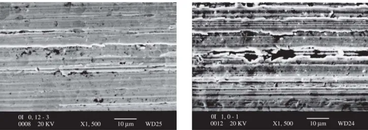
Figure 8 shows the SEM micrographs of workpieces ground at velocities of 0.12 mm/min and 1.00 mm/min, using pure oil. Figure 9 shows the tests performed with the 5% emulsion. Both images were magnified 1500 times.
An analysis of Figs. 8a and 8b indicates that the worst finish was obtained at a velocity of 1.00 mm/min, as evi-denced by the significant disparity between the lines left by
the grinding wheel on these workpieces. Figure 8b shows the workpiece with the best finish; this workpiece was ground at an infeed rate of 0.12 mm/min. The infeed rate of 1.00 mm/min was also found to produce a higher superfi-cial roughness, confirming the data obtained for the SEM analyses.
A comparison of the infeed rates of 0.12 mm/min and 1.00 mm/min using emulsion (Figs. 9a and 9b) reveals that the best surface was obtained at an infeed rate of 0.12 mm/min, although this difference was relatively slight. This fact is indi-cated by the average roughness values obtained in these tests, which were 3.55 µm and 3.80 µm, respectively.
Figures 9a and 9b show substantial superficial deforma-tion and/or a greater crushing area when compared with Figs. 8a and 8b, which represent tests in which the grinding fluid was pure oil. This difference was attributed to the out-standing lubrication property of the pure oil, which gener-ated smaller forces, causing lower vibration in the grinder and producing a better finish.
These results lead us to conclude that the finish using pure oil as grinding fluid was far superior to that obtained with the 5% emulsion, since the workpieces produced with the emulsion showed side furrows and slightly greater ma-terial flow due to this grinding fluid’s lower lubricating ca-pacity.
6.6. Roundness errors
The roundness measurements were taken at various ran-domly selected sections of the workpiece. Each point in the graph in Fig.10 represents the average value of the three repetitions performed for each condition tested, with six roundness error measurements taken for each repetition. Therefore, each point in the graph represents the average value of 18 roundness measurements.
Figure 7. Roughness behavior vs. infeed rates.
Cylindrical Grinding Processes Using a Conventional Wheel
Figure 8. SEM micrographs of the ground workpiece surface: a) 0.12 mm/min infeed rate; b) 1.00 mm/min infeed rate.
Figure 10. Comparison of grinding fluids as a function of round-ness error.
Figure 10 compares the average roundness error values of the two grinding fluids. Although the first point in the graph indicates a higher roundness error in tests performed with pure oil, a significant difference can also be observed in the other values, indicating that the emulsion displayed a higher overall roundness error.
With the exception of the 0.12 mm/min infeed rate val-ues for the pure oil, the other valval-ues indicated an increasing behavior, leading to the conclusion that the higher the infeed rate, the higher the roundness error. Some kind of problem may have occurred with the ground workpieces at this infeed rate using pure oil.
According to Fig. 10, the lower roundness errors using pure oil are attributable to the higher lubricating power of this fluid. In other words, the lubricating power of this cut-ting fluid leads to improved roundness.
with increased infeed rates, which is in agreement with the conclusions of Biera et al. (1997). The fact that the differ-ence in roundness error was so slight may be explained by the long spark-out time (8 seconds), which produced greater regularity in the workpieces, thus decreasing the roundness.
7. Conclusions
Based on the results obtained in our tests, it can be stated that the use of pure oil decreases the grinding force, spe-cific energy, acoustic emission and roughness values. These characteristics result from the high lubricating power of pure oil, which decreases the friction and reduces the generation of heat in the grinding zone. Therefore, pure oil used as a grinding fluid to obtain high quality superficial dressing and lower tool wear is the best choice for industrial applications. However, it is essential to emphasize the importance of using individual protective equipment, in view of the risks this oil may represent to the health of grinding operators.
Regrading the roughness values obtained, no variations were found that might indicate a behavior relating to the infeed rate. In other words, the roughness did not increase as a re-sult of higher infeed rates. According to Hara (1999), spark-out invalidates this effect. However, in tests performed with pure oil, the lubricating effect of this cutting fluid led to much lower roughness than the 5% emulsion.
The SEM analysis did not reveal any significant data about the workpieces, but other types of tests may indicate signifi-cant factors, such as thermal damage. The SEM micrographs revealed abrasive grains plowed through the grinding holes on the parts. These “holes” represent the grinding effect de-scribed by Malkin (1989), i.e., plowing.
One parameter that was not affected by the spark-out ef-fect was the roundness error, which exhibited an increase as the infeed rate increased, and higher roundness errors were found in workpieces ground with the emulsion. This is ad-missible, since the roundness is closely associated with the vibrations in the system, which, in turn, is related with the intensity of the tangential forces of the process.
Therefore, it is believed that higher infeed rates can be employed in grinding processes with no damage whatsoever to workpieces, provided the spark-out operation is maintained to assure the desired workpiece profile and accuracy.
As for the several infeed rates analyzed in this study, the use of the 1.0 mm/min velocity was found to be highly ad-vantageous, since the grinding tangential force values in-creased only slightly when compared with the infeed rate of
0.12 mm/min.
The tests at lower infeed rates took up to 30 min, while the tests at higher infeed rates took no more than 16 min. Therefore, from the standpoint of industrial production lines, an infeed rate of 1.00 mm/min could be highly cost-effective because of the significantly shorter processing time involved.
References
1. Baradie, M.A. El. “Cutting fluids: Part I. Characteriza-tion”. Journal of Materials Processing Technology, n. 56, Irlanda, p. 786-787, 1996.
2. Biera, J.; Vinolas, J.; Nieto, F.J. “Time-Domain Dynamic Modeling of the External Plunge Grinding Process”, Int. J. Machining Tools Manufacturing, v. 37, n. 11, p. 1555-1572, 1997.
3. Hara, C.M. “A contribution to the monitoration of cy-lindrical grinding process”. P.hD. Thesis - UNICAMP, Campinas - São Paulo, Brazil, 1999.
4. Knapp, B.R.”Benefits of Grinding with Variable Workspeed”. Thesis in Mechanical Engineering, Penn-sylvania State University, p. 63, 1999.
5. Lee, E.S.; Kim, N.H. “A Study On The Machining Char-acteristics In The External Plunge Grinding Using The Current Signal Of The Spindle Motor”. International Journal of Machining Tools & Manufacture, 2001. 6. Malkin, S. “Grinding Mechanisms” e “Grinding
Tem-peratures and Thermal Damage”, In: MALKIN, S. Grind-ing Technology: theory and aplications of machinGrind-ing with abrasives. ed. 1, Chichester, EllisHorwood Lim-ited, 1989.
7. Minke, E. “Contribution to the Role of Coolants on Grinding Process and Work Results”. 3rd International Machining & Grinding Conference, Cincinnati, Ohio, 1999.
8. Motta, M.F.; Machado A.R. “Cutting fluids: types, func-tions, selection, application methods and maintenance”. Machines and Metals Magazine, Brazil, p. 44-56, 1995. 9. Oliveira, J.F.G. “Advanced topics of the grinding proc-ess”. Notebook - School of Engineering of São Carlos, São Paulo University, São Carlos, Brazil, p. 94. 10. Runge, P.R.F.; Duarte, G.N. “Lubricants in the
indus-tries”. Cotia - SP: Triboconcept Technical Editions, p. 71-171, 1990.