Structural performance assessment of reinforced
concrete lat slab-edge column connections under the
effects of outward eccentricity
Avaliação do desempenho estrutural de ligações de
borda em lajes lisas de concreto armado sob os efeitos
da excentricidade externa
a Universidade de Brasília, Faculdade de Tecnologia, Departamento de Engenharia Civil e Ambiental, Campus Universitário Darcy Ribeiro, Brasília – DF, Brasil.
Abstract
Resumo
Although several advantages – either constructive or architectural - are assigned to lat slabs, the continuity between consecutive spans in multiloor buildings may turn slab-column connections into a critical region, due to the limited contact between both elements. When transferring moments caused by horizontal and/or vertical eccentric loads are present, these effects are even more pronounced on external panels. Speciic studies on the effects of outward eccentricities are still rather scarce, although it is recognized that the codes, in general, are concerned with even-tually meeting all potential cases, seeking to improve safety structural performance. Some current recommendations are based on considerable extrapolations, whose theory was originally developed for cases of asymmetric loading at internal connections and need to be consolidated with speciic test data. Thus, to investigate the structural behaviour of slabs-edge columns connections, four specimens were tested, reproducing a 2,350 mm x 1,700 mm portion of a 180 mm thick reinforced concrete slab adjacent to a 300 mm x 300 mm cross section squared edge column, with a projection at the base for the imposition of eccentricities. The position of the support under the column has determined the eccentricity, dein-ing in physical terms the interaction between benddein-ing moment and shear force, as follows: 300 mm (inward), centred (reference) and 300 mm and 400 mm (outward). Experimental results allowed to comparatively assess the performance of the specimens relating the strain measurements in steel and concrete, vertical displacements, rotations, failure mode and ultimate loads of the slabs. Results indicate that the inluence of transferring moments on failure modes is much more pronounced than the shear action in the case of edge connections subjected to outward eccentricities. Keywords: lat slabs, edge column, eccentricity, punching shear, reinforced concrete.
Embora diversas vantagens – construtivas e/ou arquitetônicas – lhe sejam atribuídas, a continuidade entre vãos consecutivos de lajes lisas ado-tadas em projetos multipavimentos faz da ligação laje-pilar uma região crítica, dada a reduzida seção de contato entre os dois elementos. Com a transmissão de momentos devido à adição de carregamentos horizontais e/ou verticais excêntricos, esses efeitos são ainda mais pronunciados em painéis externos. Estudos especíicos sobre os efeitos de excentricidades externas ainda são bastante escassos, embora se reconheça a preocupação das normas, em geral, estarem aptas a atender eventualmente todos os potenciais casos conexos, visando um desempenho estru-tural seguro. Para o caso de ligações de borda, algumas das recomendações existentes são baseadas em extrapolações bastante consideráveis, cuja teoria foi originalmente desenvolvida para os casos de carregamento assimétrico em ligações internas e precisam ser consolidadas com dados experimentais especíicos. Assim, para investigar o comportamento estrutural das ligações entre a laje e o pilar de borda foram ensaiados quatro specimenos individuais que reproduziram uma porção de laje de 2.350 x 1.700 mm de um pavimento de concreto armado com 180 mm de espessura em torno do pilar de borda quadrado de seção transversal 300 mm x 300 mm, dotado de uma projeção para imposição das excen-tricidades. A posição do apoio sob o pilar determinou a excentricidade em termos físicos, variável estudada que deiniu a interação M/V, a saber: 300 mm (interna), centrada (referência) e 300 mm e 400 mm (externa). Os ensaios experimentais possibilitaram avaliar comparativamente o comportamento dos specimenos quanto às medições de deformações no aço e no concreto, deslocamentos verticais, rotações, modo de ruptura e cargas últimas das lajes. Os resultados indicam que a inluência da transferência dos momentos nos modos de ruptura das lajes é muito mais pronunciada que ação do cisalhamento nos casos de ligações de borda submetidas a excentricidades externas.
Palavras-chave: lajes lisas, pilar de borda, excentricidade, punção, concreto armado.
N. G. B. ALBUQUERQUE a
G. S. S. A. MELO a
1. Introduction
Reinforced concrete lat slabs structures have been established as a viable alternative to conventional system of solid slabs, beams and columns, emphasizing its functionality and its economy. Among their advantages is that the elimination or reduction of the number of beams implies reducing materials and labour related to formwork manufacturing and wall covering, as well as promoting greater agility in executing services such as: installation of rein-forcing steel, placement and compaction of concrete and removal of formwork [1]. However, it is necessary to watch out for while implementing this system, especially because among some of top-ics they include the possibility of failure by punching at the slab-col-umn connection. This failure type is fragile and occurs when shear becomes critical, so that the connection behaviour is important to know about. Another noteworthy aspect regarding punching failure is that when it occurs, there is a great possibility of progressive col-lapse to happen throughout the structure, if it is not able to absorb the extra forces due to load redistribution.
Many studies on this subject are needed since the main international codes have differences among themselves. Conducting experimen-tal studies is crucial to understand punching-shear phenomenon, since it allows a comparison and its suitability to code’s provisions aiming a safe and economic design. When it comes to edge column connections with transferring moment the amount of existing studies is greatly reduced, and when the bending moment is the result of an outward eccentricity, the references are scarce [2], [3].
In a real situation, transferring moment can occur, for example, in a structure under the effect of earthquakes. Another cause is the existence of horizontal forces induced by wind or even a situation in which the eccentricity is foreseen by project. Generally, there are two tests that simulate a moment transferred from column to slab:
those resulting from horizontal forces on the stubs of a column and those whose eccentricity is imposed under the column support, as shown in Figure 1. The last option was adopted in this work as it was considered more appropriate to the available test setup and loading apparatus. Thus, these two possible cases of transferring moment about an axis parallel to the slab edge are exempliied, deining directions as inward or outward eccentricity depending on the column rotation (that is taken as inward when the column stub extended below the slab rotates toward the interior; and as out-ward when the column rotates in the opposite direction).
2. Experimental program
2.1 Design of test specimens
Punching tests here described were part of the work of Feliciano [4] and Albuquerque [5], which comprised a series containing four specimens reproducing the region of the slab around an edge col -umn. An original and unpublished test setup was adopted regard-ing the deinitions of boundary conditions used to perform tests of this nature; it comes, therefore, an appropriate measure, given its economic feasibility, simplicity in design, especially for represent -ing the actual behaviour of a real structure.
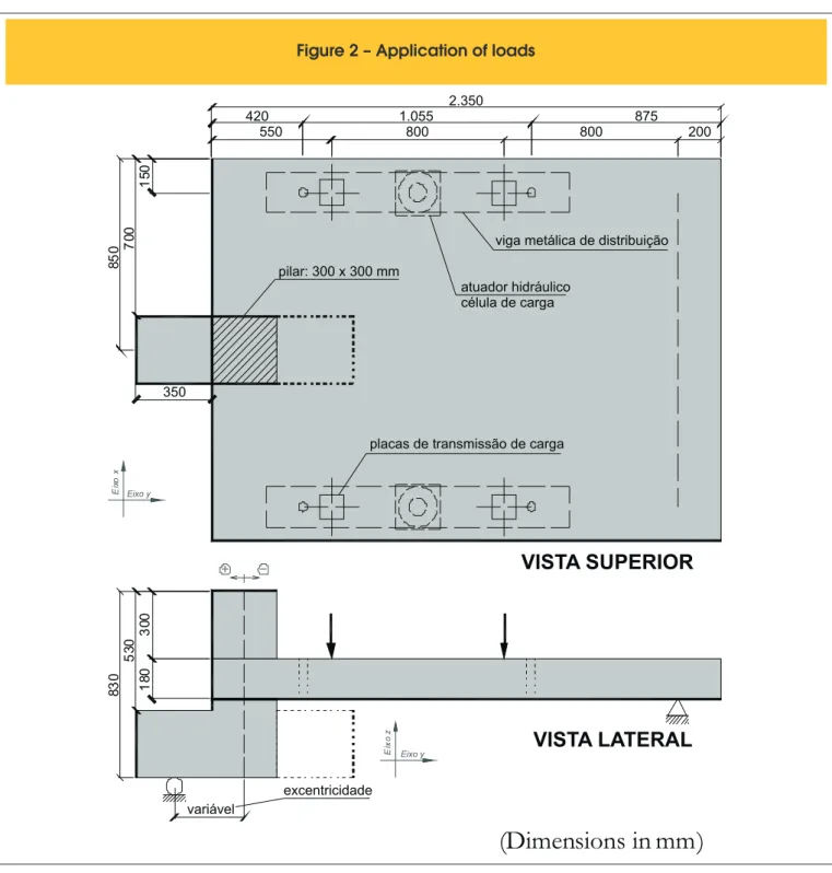
The four specimens were simply supported in the largest dimen -sion side (longitudinal direction or x-axis) of the slab, using a roller under the column base and a continuous pin near the other end. Load was applied via two hydraulic actuators attached to load cells positioned directly above the distribution beams at the ends of the shortest dimension side (transverse direction or y-axis), through four steel
plates equally
positioned about the centre of the jacks, as shown in Figure 2. The position of the support under the col-umn determined the eccentricity, and the colcol-umn projection wasFigure 1 – Behaviors generated by: (a) inward eccentricities; (b) outward eccentricities
A
B
conveniently orientated in accordance to the variable direction. Table 1 shows the eccentricity used for each specimen, consider -ing outward eccentricity as positive.
2.2 Construction of slab specimens
2.2.1 Geometry
Specimens were constructed with overall dimensions of 1,700 mm by 2,350 mm and 180 mm thick slab, connected to a 300 mm by
300 mm column of 830 mm height, which extended a projection of 350 mm for imposing the support eccentricity related to the column axis, being 300 mm height of from the base of the column. Dimen-sions were deined in order to adapt to the existing frame arrange -ment in the Structures Lab at University of Brasilia. The column projection was oriented toward exterior for slabs with centred or outward eccentricity; and it was oriented toward interior when ec-centricity was inward. Figure 3 illustrates a representation of the loading and the boundary conditions for slabs where projections shall comply with either shown direction.
Figure 2 – Application of loads
(Dimensions in mm)
2.350 1.055 550
420 875
800 800 200
83
0
53
0 30
0
18
0
85
0 700
15
0
350
viga metálica de distribuição
atuador hidráulico célula de carga pilar: 300 x 300 mm
placas de transmissão de carga
VISTA SUPERIOR
VISTA LATERAL
Eixo y
E
ixo
x
Eixo y
E
ix
o
z
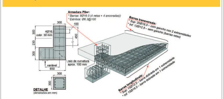
2.2.2 Slab reinforcement
The slabs were reinforced to bending in both directions. Reinforce -ment at the top consisted of 15 bars with a diameter of 12,5 mm arranged at a spacing of 100mm in longitudinal direction, being folded as a hook at one extreme end (close to column edge) and 20 straight bars with a diameter of 16 mm arranged at a spacing of 100 mm in the transverse direction, attached to hooks at both ends. Reinforcement at the bottom consisted of 15 bars with a di
-ameter of 16 mm arranged at a spacing of 100 mm the longitudinal direction, being folded as a hook at one extreme end (close to col-umn edge) and 12 straight bars with a diameter of 16 mm arranged at a spacing of 200 mm in the transverse direction.
2.2.3 Column reinforcement
Vertical column reinforcement was provided by adding 8 bars with a diameter of 16 mm that composed four straight bars and four “corbel” anchoring bars. As column ties, conining stirrups with a diameter of 6,3 mm were used, being spaced at 100 mm. Figure 4 schematically shows the distribution of the reinforcement in both column and slab.
2.2.4 Construction sequence
The specimens have been monolithically cast at the same day with ready mix concrete with a nominal compressive strength speciied in 40 MPa. Brazilian West Central region crushed aggregate was used, such as sand and gravel. The maximum coarse aggregate size was 9.5 mm. Workability test was carried out on concrete be
-Figure 3 – Longitudinal view of the model
Table 1 – Eccentricities under column supports
Specimens e (mm)
L1 -300 (inward) L2 0 (centred) L3 300 (outward) L4 400 (outward)
Table 2 – Ultimate loads and failure modes
Specimens e (mm) f’c (MPa) fct (MPa) Ec (GPa) Vu (kN) Pu (kN) Failure mode
L1 -300 46.8 3.4 29.3 308 437 Punching*
L2 0 44.7 3.0 27.5 315 525 Punching
L3 300 45.1 3.1 27.1 256 490 Flexural
L4 400 46.0 3.3 28.5 210 420 Flexural
Figure 4 – Flexural reinforcement at: (a) top; (b) bottom
A ASEÇÃO AA
barra dobrada ga nch o Ø 12 .5SE
Ç
Ã
O
B
B
B BARMADURA SUPERIOR
6Ø 12 .5 @ 12 0 6Ø 12 .5 @ 12 0 3Ø 12 .5 @ 9015 Ø 12.5
20 Ø 16 .0 17Ø16.0@120 18 0
cobrimento: 20 mm
3Ø16.0@90 6 x 12 0 6 x 12 0 A' 8Ø12.5@240
3Ø12.5@90 120 B'
A'
B'
ARMADURA INFERIOR
15 Ø 16.012
Ø
12
.5
cobrimento: 20 mm
fore it was poured into the formwork by slump cone test resulting 12 cm. Moulds were cleaned and oiled on all their contact surfaces and illed in layers with freshly mixed concrete for vibration using 25 mm diameter immersion vibrator and then curing. Compressive
strength tests, split tensile tests and elastic modulus tests were carried out on 30 cylindrical samples (100 mm x 200 mm) manu-factured according to Brazilian standards NBR 5739 (2007) [6], NBR 7222 (2011) [7] and NBR 8522 (2008) [8], respectively.
Figure 5 – Schematic distribution of the reinforcement at the column and slab
Figure 6 – Points of instrumentation
200
30
0
20
0
300 300 300 900
1 2 11 30 0 13 Superfície Superior Superfície Inferior Eixo y E ixo x
3 4 5 6
7 8 9 10 12 DESLOCAMENTOS VERTICAIS Ponto Monitorado B or da d a L aj e DEFORMAÇÕES NA SUPERFÍCIE DE CONCRETO ETS2 ETS1 ETS3 ELS3 ELS2 ELS1 ETS4 ETS5 ELS4 ELS5 ETI2 ETI1 ELI3 ELI2 ELI1 ETI4 ETI5 ELI4 ELI5 ETI3 Ø12.5 Ø16.0
Ø12.5 Ø 16 .0 B or d a d a La je B or d a d a L aj e DEFORMAÇÕES NA
ARMADURA SUPERIOR DEFORMAÇÕES NAARMADURA INFERIOR
2.3 Instrumentation of slabs
To investigate the behaviour of the slabs during the test, measure-ments of strain on steel and on concrete surface as well as vertical and horizontal displacements have been collected at some strate-gic points that when mounted at the structure (Figure 6).
KYOWA electrical resistance strain gauges were attached to steel bars in order to determine the distribution of strain within the 20 instrumented points that contained two strain gauges glued on diametrically opposite sides, in both top and bottom reinforcement arranged on x and y axes; Strain in the concrete surface was also measured at different points by adapting them to rosettes, although part of the generated data have not
seemed consistent. Because in most cases strain gauges have failed in tension, there is some evidence of cracking, damage or detachment of the sensor, and for this reason, are presented just the results of the monitored point positioned at the column inner corner.
Vertical and horizontal displacements were measured with LVDTs (linear voltage displacement transducers) from HBM type WA50, whose output was recorded and stored electronically with good accuracy. For vertical displacements measurements 15 LVDTs monitored the delections at characteristic points on longitudinal, transverse and diagonal axes, aligned at 45 degrees from the col-umn inner corner, where most of them were mounted underneath the slab. In addition, column rotation was detected from relative horizontal displacements readings between top and bottom stubs. Aluminium targets were glued to the concrete surface to create a better surface for reading displacements.
3. Testing procedures
Measured data such as strains, displacements and applied loads were processed by HBM Catman [9] software associated to HBM Spider 8 data acquisition system. All 68 channels of 9 modules were used, being controlled by 2 computers that recorded all elec -tronic test data from LVDTs (15), steel strain gauges (40), concrete strain gauges (9) and load cells (4).
The load applied by the hydraulic jacks was monitored by the conjugated KRATOS 1,000 kN capacity load cells, that were used only to control the pump operation. The four remaining hollow load cells, from HBM type C6A, were attached to the tie rods for parity checks and reading of data redundancies.
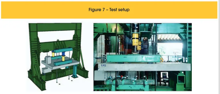
Oil low was driven by electric pumps, which powered two Enerpac hydraulic actuators that transmitted loading to the piston/rod as-sembly and, subsequently, distributed the load equally to slab by four thick steel plates. The test was carried out on the specimens incrementally up to failure, using the reaction frame anchored to the Structures Lab strong loor at the University of Brasilia. The load application system is shown in Figure 7.
Figure 7 – Test setup
Figure 8 – Total load (P ) and edge
u4. Results and discussions
4.1 Ultimate loads and failure modes
The test results were analysed and compared through tables and graphs. Table 2 summarizes the observed failure modes at ulti-mate loads, where Vu corresponds to the column support reaction (or connection capacity), calculated statically in the longitudinal direction, and Pu is the total load applied to system, considering slabs’ self-weight and equipment’s loading.
By comparing the results of the connection capacity (Vu) shown by L1 and L3 it conirms the hypothesis of an outward eccen-tricity is more critical than inward since, although they have the same value of eccentricity, the column support reactions (Vu) corresponds, respectively, to 308.5 kN and 255.7 kN,
repre-senting a decrease of 17.1%. A larger amplitude of total load resisted by L1 is explained by the test setup, in which the con -tinuous pin support located on the opposite side to the column edge attracts a smaller proportion of the load. Yet, comparing systematically Vu of L2, L3 and L4, it seems that increasing the outward eccentricity leads to a reducing on the connection load capacity. Confronting the two cases of outward eccentricity, L3 and L4, the addition of 100 mm to the eccentricity imposed a reduction by 17.9% to the connection load capacity. Figure 8 illustrates this behavior.
Unlike L1 and L2, which failure were abrupt and not preceded by an increase in the delection, specimens L3 and L4 with outward eccentricity have shown that failure modes were mainly deter-mined by transferring load than by shear, even though failure has led to the formation of the punching cone at the end of the test.
Figure 9 – Relationship between load and strain of longitudinal top bars
A
C
B
4.2 Strains on lexural reinforcement
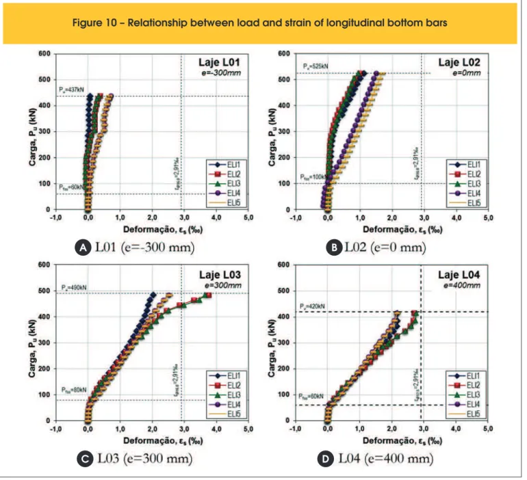
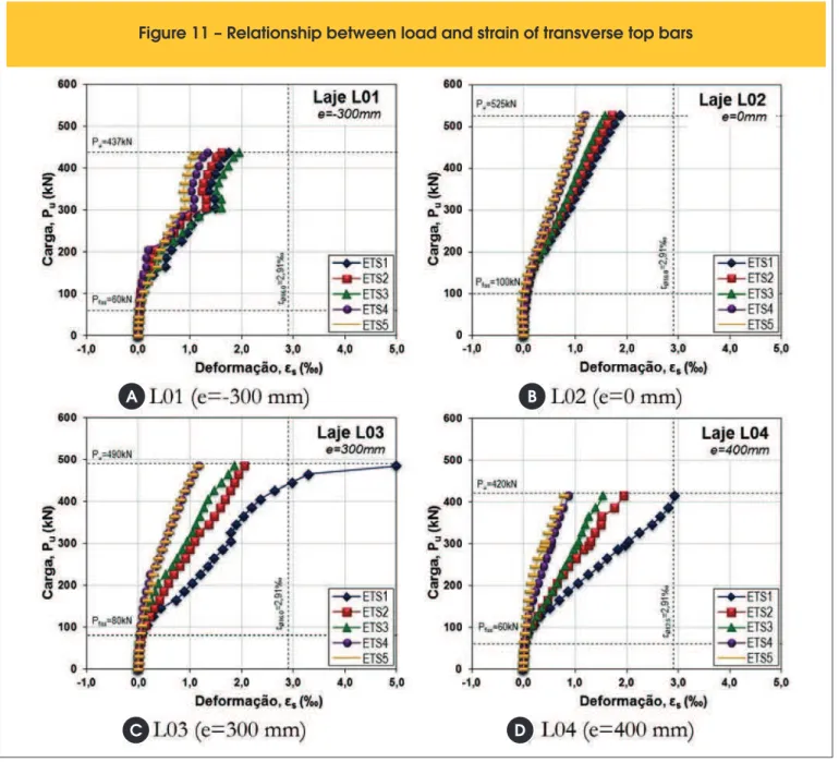
Reinforcement strains are presented in the graphs of Figure 9 to Figure 12, being plotted against the applied loads at the predeined points of instrumentation, where is indicated the irst visible crack load, the failure load as well as the yield strength correspondent to the rebar of same diameter.
It was observed that the gauges on the top longitudinal bars, ELS, and top transverse bars, ETS, presented predominantly tensile strains in L1, being worth emphasizing that the column was subjected to an inward eccentricity and so vertical loading also caused tension to slab edge in both longitudinal and transverse directions at the near region of the col-umn. Higher strains can easily be seen in the column longitudinal axis near its front face, with bars reaching yield strain. Top transverse strains in L1 were also accentuated next to the column front face.
For slabs with outward eccentricity, the highest strains were col-lected at the gauges located on the bottom longitudinal bars, ELI, and top transverse bars, ETS, indicating a “horse saddle” effect, given its overall deformed shape. As for the slab L1 (i.e., with no eccentricity), it exhibited an intermediate behaviour be-tween both cases.
Thus, for L2, L3 and L4, the predominance of the effects on the longitudinal direction were within the column strip, where the slab was subjected to a positive bending moment, since its bottom i-bres were in tension and top ii-bres in compression. This behaviour is conirmed by L2, L3 and L4 load-strain graphs at the top longi-tudinal reinforcement, showing that by increasing eccentricity the higher are the strains around the column region, as the applied moment is greater. Only ELS1 on slabs L3 and L4 presented com -pressive strains, which can be explained by the fact that this gauge
Figure 10 – Relationship between load and strain of longitudinal bottom bars
A
C
B
was not located at bars crossing the column, so they were subject to the inluence of bars on the other direction.
Load-strain graphs of L2, L3 and L4 at the top transverse bars show that the arrangement of the vertical loads generated only negative bending moment in all cases, so that tensile strain near the slab edge or next to the column frontal face may vary to a greater or lesser extent depending on the column rotation due to the eccentricity direction. As for the bottom transverse reinforce -ment, the graphs revealed that strain at top and bottom bars had the same sign convention in various sections of the slab. For L1 it happened to almost all instrumented points along the longitudinal direction. For L2, whose column had no moment, even presenting lower strains along the longitudinal direction, all top and bottom strains had opposite signs. The eccentricity and, consequently the column rotation, had just limited more or
less the strains closest to either outside or inside (frontal) faces of the edge column.
4.3 Strains on concrete surface
Another graphic was constructed to represent the concrete strains versus applied load at the point where monitoring was more ef-icient (Figure 13). Only a gauge glued in the transverse direction presented comparable compression strains for all slabs, according to what had been explained about the slabs behaviour in connec-tion with the gauge on steel bars.
Comparing the results of the strain gauges aligned to the column fron-tal face in the transverse direction is was noticed that with an increas-ing eccentricity to outwards, readincreas-ings developed into larger strains, being higher in L3 and L4, falling by half for the same load level in
Figure 11 – Relationship between load and strain of transverse top bars
A
C
B
L2, and then to a lesser extent in L1, when starts to deviate from the trend and reach positive values, caused by intense local cracking. The maximum strain observed was close to -1.5 ‰ for L3 and L4, though, it should be noted that, among the collected data that remained con-sistent on other points not related here, the larger strains on concrete surface occurred near the inner corner of the column axially placed at 45 degrees, reaching values that exceeded -1.5 ‰.
4.4 Column rotations
From the relative values of horizontal displacements measured at LVDT 14 and LVDT 15, it is observed that column rotates in dif-ferent directions, according to the applied eccentricity which was given to the supporting point. The only specimen that reproduced inward eccentricity, L1, developed a rotation towards the outer
direction with respect to the slab, as it moved the axis of rotation away from the column centre. Despite the column of L2 is not subjected to signiicant bending moments, the continuity of the slab-column connection contributes in its rotation, causing it to pivot but in a small magnitude range towards the inner direction of the slab. As for the outward eccentricity specimens, results indicated that increasing the eccentricity implies a larger column rotation. However, it must be noted that as ultimate load of L4 is less than L3, the latter is allowed to rotate up to a higher level of loading, reaching higher values.
The development of the angle of column rotation can be seen in the graph of Figure 14, which represents the column rotation against load. It is apparent that the absence of eccentricity lead to a more acclivitous curve of the connection’s rotation capacity, and also states that, for the same load level, the increase of outward
eccen-Figure 12 – Relationship between load and strain of transverse bottom bars
A
C
B
Figure 13 – Relationship between load
and concrete strain
Figure 14 – Relationship between load
and column rotation
Figure 15 – Vertical displacements along the longitudinal axis of the slab
A
C
B
tricity caused the column to rotate more quickly, compared to inward.
4.5 Vertical displacements
As for the vertical displacements, the delected shape is graphi -cally shown along the longitudinal axis (Figure 15) and transverse axis (Figure 16), both aligned on the centre lines of the column and also along the diagonal axis (Figure 17), aligned at 45 degrees from the column inner corner.
The graph of vertical displacements along the longitudinal axis for L1 shows that with the application of load, inward eccentricity caused the column to move downwards and rotate towards the outer direc-tion of the slab, inducing a slight upward movement in the region nearby the frontal face of the column. Vertical displacements along the transverse direction of L1 have shown that due to the direction of the column rotation, displacements along the edge strip of the slab were more pronounced than its perpendicular direction.
Slabs L2, L3 and L4 presented a similar displacement pattern among
each other, increasing the magnitude of the displacements the larger the eccentricity was. Regarding L3 and L4, the slabs have delected signiicantly up to the formation of the failure punching cone. Further-more, it was apparent that larger eccentricities generated consider -ably increased displacements measured above the column in relation to its adjacent points in both directions, giving evidence of possible torsion on the edge connection. It was observed that the point moni-tored by the LVDT 13, although it should be ideally mirrored to LVDT 11, showed considerably higher values. However, by disregarding these measurements, it can be observed for all slabs that the larg-est displacements occur in the diagonal axis just below the loading plates (LVDT 12). Another possible observation include that the high -est magnitude point tends to move from the slab mid-span towards to the edge connection vicinity along the longitudinal axis.
4.6 Cracking pattern
Figure 18 illustrates the slabs resulting cracking pattern after
fail-Figure 16 – Vertical displacements along the transverse axis of the slab
A
C
B
ure, checked on both top and bottom surfaces, particularly the re-gion nearby the edge connection since, in general, cracks followed paralleled to the alignment of the reinforcing bars on regions far from connection.
On top surface of the slab, L1 presented the irst visible crack in the vicinity of the frontal face of the column at an applied system load of 60 kN, while the region next to the lateral faces of the column be-gan to crack at a load of 100 kN. Some apparently torsional cracks were also observed, beginning at the sidesof the column, following after diagonally to the slab edge and then developing through the slab thickness to converge on more distant points. These cracks occurred only in this specimen, which can be explained by the di -rection of rotation of the column.
Analogously to L1, a higher concentration of cracks occurred in L2 next to the column frontal face. However, in this specimen, cracks that were guided toward the slab edge had a minor slope.The irst visible crack occurred at a load of 100 kN, also close to the frontal face of the column, while in the vicinity of the column sides crack occurred only at 180 kN.
Figure 17 – Vertical displacements along the diagonal axis of the slab
A
C
B
D
L3 and L4 showed cracking pattern very similar to each other, where some cracks developed diagonally to the slab edge, although in the opposite direction L1. In these specimens the failure cone were formed closer to the column frontal face, especially in L4, which ap-pears to be due to eccentricity. L3 specimen exhibited irst cracks at a load of 60 kN and 100 kN, respectively, near frontal and lateral faces of the column, while L4 cracked at 80 kN and 160 kN. All specimens showed similar behaviour considering the bottom surface of the slab. By dividing the slab into three longitudinal segments, the inner segment showed predominantly transverse cracks, while in the other two segments, cracks were inclined up to the edge, indicating the presence of torsion due to a different bending behaviour of the slabs in two directions.
5. Conclusions
indicatives of edge connections behaviour subjected to outward eccentricities. Points of instrumentation provided representative data from the tested slabs, which were useful in accomplishing the analysis on the eccentricity effects on slabs’ behaviour. By monitoring both the top and bottom bars at the same section, it was possible to verify the strains distribution at different cross sections, compensating, to some extent, the lower eficacy of the concrete gauges glued to the slabs’ sofit, which may not followed the struts directions.
Thus, among the possibilities that can be attributed to the inlu -ence of outward eccentricities on the connection strength, it was found that for large outward eccentricities: cracks’ opening level is relatively higher than cases of inward eccentricities; torsional crack reaches the free edge on farthest points of connection; concrete strains are comparatively more pronounced; punching failure cone is apparently developed closer to the front face of the column; the largest displacement along the longitudinal axis is movable, tend-ing to get closer to the edge connection as the eccentricity increas -es; ultimate failure loads are much more penalized in connections subjected to outward eccentricities than inward ones.
Figure 18 – Cracking pattern
A
A
A
A
L01 (e=-300 mm)
L03 (e=300 mm)
L02 (e=0 mm)
L04 (e=400 mm) Top
surface
Top surface
Top surface
Top surface Bottom
surface
Bottom surface
Bottom surface
Bottom surface
6. Acknowledgements
The authors would like to thank Prof. PE Regan, Emeritus Profes-sor at the University of Westminster (London, UK), for the valu-able theme suggestion and throughout this research, as well as the Brazilian Scientiic and Technological Research Funding Agencies, CNPq and CAPES for the inancial support.
7. References
[01] WIGHT, J. K.; MACGREGOR, J. G. Reinforced Concrete: Mechanics and Design. New Jersey, NY: Prentice Hall, 6ed, 2011, 1157p.
[02] NARASIMHAN, N. Shear reinforcement in reinforced con-crete column heads, London, 1971, Thesis (PhD) - Faculty of Engineering of University of London, Imperial College of Science and Technology, 267p.
[04] FELICIANO, F. M. H. Punção em lajes lisas de concreto ar-mado com pilares de borda e excentricidade externa, Brasí -lia, 2011, Dissertação (mestrado) - Faculdade de Tecnolo-gia, Universidade de Brasília, 149p.
[05] ALBUQUERQUE, N. G. B. Comportamento das ligações de lajes lisas de concreto armado com pilares de borda sujeitas a excentricidades interna e externas, Brasília, 2014, Tese (doutorado) - Faculdade de Tecnologia, Universidade de Brasília, 204p.
[06] ASSOCIAÇÃO BRASILEIRA DE NORMAS TÉCNICAS. Concreto – Ensaio de compressão de corpos-de-prova cilín-dricos – Métodos de ensaio - NBR 5739, Rio de Janeiro, 1994.
[07] ASSOCIAÇÃO BRASILEIRA DE NORMAS TÉCNICAS. Ar -gamassas e concreto – Determinação da resistência à tra-ção por compressão diametral de corpos-de-prova cilíndri -cos – Método de ensaio - NBR 7222, Rio de Janeiro, 1994. [08] ASSOCIAÇÃO BRASILEIRA DE NORMAS TÉCNICAS.
Concreto – Determinação do módulo de deformação elástica e diagrama tensão deformação – Método de ensaio - NBR 8522, Rio de Janeiro, 1994.