Analysis of the behavior of reinforced concrete columns
strengthened with sleeve wedge bolts and a self
compacting concrete layer
Análise experimental de pilares de concreto armado
reforçados por encamisamento com camada de
concreto auto adensável
a Federal University of Goiás, School of Civil Engineering, Goiás, Brazil.
Abstract
Resumo
Strengthening of reinforced concrete columns by jacketing is one of the most common structural rehabilitation techniques in Brazil. For adequate performance, it is necessary, among others, to avoid detachment of the new concrete layer (strengthening material) from the old concrete sub-strate when the strengthened member is again in service conditions. This paper describes the test results of eight reinforced concrete rectan-gular columns subjected to combined compression and one-axis bending to evaluate the eficiency of using sleeve wedge bolts across the new concrete/old concrete interface to avoid detachment. The strengthening technique, in this case, consists of adding a layer of self-compacting concrete to one face of the column. Two columns tested were monolithic and named PO (original column) e PR (reference column). The other six columns were strengthened using a new 35 mm thick self-compacting concrete layer attached to the column face subjected to highest compres-sive stresses. Column PO had a 120mm by 250 mm rectangular cross section and its results gave information about column behavior without the use of strengthening. Column PR had a 155mm by 250 mm rectangular cross section and its cross section dimensions matched the strengthened columns but it was cast monolithically. To improve bond conditions between the existing concrete and the new concrete, the concrete surface was roughened and the outermost aggregate was exposed using hydro jetting. Holes along the concrete surface were made to insert the wedge bolts responsible for increasing the bond between the two concrete surfaces. The difference among the six strengthened columns was the position and amount of bolts used. Results indicate that the position and amount of the bolts alters signiicantly the strength capacity of the columns, since premature rupture by concrete detachment was delayed.
Keywords: column, reinforcement, wedge bolts, bending, compression, bond.
Para que um elemento estrutural reforçado por encamisamento tenha um desempenho satisfatório é necessário garantir a transferência de esforços na região da junta do concreto antigo (substrato) com o concreto do reforço. O desplacamento entre o concreto adicionado (material do reforço) e o concreto antigo deve ser evitado quando a peça reabilitada é colocada novamente em serviço. Foram ensaiados oito pilares de concreto armado, submetidos à lexo-compressão reta, reforçados com concreto auto adensável e chumbadores metálicos cruzando a interface de ligação entre os concretos moldados em idades distintas, para evitar o desplacamento entre estes materiais. Dos oito pilares ensaiados, dois eram referências e foram denominados de PO (pilar original) e PR. (pilar referência). Os outros seis foram reforçados acrescentando-se uma camada de concreto auto adensável de 35 mm à face comprimida. O pilar PO, tinha seção transversal de 120 x 250 mm, e forneceu informações sobre o comportamento da peça antes da execução do reforço. O pilar PR tinha seção transversal de 155 x 250 mm, e forneceu informações sobre o comportamento de uma peça monolítica de seção idêntica a dos pilares após o reforço. Para executar o reforço, inicialmente escariicou--se, por hidrojateamento, a zona de interface a ser formada pelo contato entre o concreto do reforço e do substrato. Posteriormente, izeram-se furos ao longo desta superfície, onde foram inseridos os chumbadores mecânicos responsáveis por aumentar a aderência entre os concretos. A diferença entre os seis pilares reforçados consistia justamente na variação da posição e da quantidade dos chumbadores usados em cada peça. Os resultados obtidos indicaram que a quantidade e a posição destes chumbadores interferiram signiicativamente na capacidade portante dos pilares reforçados, pois retardavam a ocorrência de uma ruptura prematura por desplacamento entre os concretos do reforço e do substrato.
Palavras-chave: pilar, reforço, chumbadores, deslocamentos e deformações.
M. G. MARQUES a [email protected]
A. P. A. R. LISERRE a [email protected]
R. B. GOMES a [email protected]
1. Introduction
Although the number of studies on the behavior of rehabilitated concrete structures has increased in the last decade, research is needed on the behavior of these structures under service loads. With this in mind, the main objective of this research is to estab-lish strategies, methods and project procedures for rehabilitation of strengthened concrete structures with an emphasis on reinforced concrete columns subjected to one-axis bending and compression. There are several techniques for strengthening reinforced concrete structures and one of the most common in Brazil consists of jacketing a concrete member by adding new concrete, with or without reinforce-ment, to the sides of the concrete member. This technique is used in columns and fragile mode of failure can result from the detachment of the new concrete added to the column face if the shear stresses re-sistance at the new concrete – old concrete interface is not adequate. Thus, there is a need to study the bond between these two concretes and to analyze the inluence of shear connectors positioned at the interface so that the rehabilitated column acts monolithically.
For the strengthened structural element to have a satisfactory per-formance it is necessary to guarantee the transfer of internal forces at the new concrete-old concrete interface. This force transfer oc-curs similarly to force transfer in composite members and it can occur through the concrete itself and through the connectors. Force transfer through the contact surface of the new and old
con-crete is basically done through adhesion, friction and mechanical action of the new substrate with the rehabilitating material. Adhe-sion of the new and old concrete occurs mainly through mechani-cal interlock or wedging. Due to capillary absorption, particles of the new concrete are gradually conined in the pores of the old concrete. As the hydration of the cement of the new concrete oc-curs, there is a physical enlace with the irregularities of the old concrete surface. Force transfer between the contact surfaces by friction appears after breakup of adhesion and this happens after any relative displacement between the strengthening concrete and the substrate. Force transfer through mechanical interlock occurs through a shear key and, in rough surfaces, it is guaranteed by the coarse aggregate across the interface.
When reinforcement across the concrete interface exists, force trans-fer can occur by dowel action. Dowel action appears when shear forc-es act at the concrete interface and relative displacement between the two concrete surfaces appear. This displacement will try to shear any bolts present across the concrete interface. The bolt offers shear resistance that is added to the shear resistance of the contact surfac-es. When relative displacement between the concrete surfaces exist, separation of the concrete surfaces will generate tension forces in the bolts and these will react by compressing the concrete surface and friction at the concrete interface will increase.
Although the evaluation of the force transfer at the interface be-tween the substrate and the new concrete is essential to the
89
IBRACON Structures and Materials Journal • 2015 • vol. 8 • nº 2
success of the rehabilitating work, there is still no consensus
among the researchers on the best way to determine the interface shear stresses. This evaluation is complex and dificult to achieve, because not only physical and chemical phenomena occur at the interface, but the interface can also be subjected to a great va-riety of stresses due to mechanical actions in the structure itself (SOUZA (1990) [1]). MORENO (2002) [2] adds that the adhesion mechanism between the two cimentitious materials is a complex phenomena due to the heterogeneous nature of the concrete sub-strate and the strengthening materials.
The mechanical properties of the strengthening material, the con-crete substrate surface preparation and the amount of reinforce-ment or bolts across the interface are some of the factors that inlu-ence interface shear resistance.
Recent work has been done at the Master’s Program in Civil Engi-neering at the School of Civil EngiEngi-neering of the Federal University of Goiás with the intent to evaluate the inluence of reinforcement or bolts across the concrete interface to resist shear stresses in columns strengthened by jacketing. The objective of these works is to evaluate the inluence of bolt type and quantity placed along the concrete interface of columns strengthened by jacketing when subjected to compression and one-axis bending.
OMAR (2006) [3], SAHB (2008) [4] and NASCIMENTO (2009) [5] studied strengthened columns and experimental evidence showed signiicant gains in column resistance as the cross section’s dimen-sions are increased by jacketing. However, although the column
Figure 2 – Sleeve wedge bolt components
91
IBRACON Structures and Materials Journal • 2015 • vol. 8 • nº 2
capacity increased compared to the original column, fragile and pre-mature rupture was observed in some columns due to detachment of the new strengthening concrete from the old concrete substrate. Hence, new work is under way at the Federal University of Goiás such as those by MARQUES (2014) [6] e FERREIRA (2014) [7].
2. Experimental program
This work presents the experimental results of eight rectangular columns subjected to compression and one-axis bending. Six of the eight columns were strengthened at the compression face with the addition of a concrete layer and use of wedge bolts along its length to increase adhesion between the old concrete substrate and the new concrete layer (MARQUES (2013) [6]).
Column nominated as PO corresponds to the original column with-out strengthening with the rectangular cross section of 120 mm by 250 mm. Six strengthened columns were originally cast with a 120mm by 250mm cross section and a 35 mm concrete layer was later added to the compression face. Therefore, the six strength-ened columns had a 155 mm by 250 mm cross section when tested and they were nominated as P150-18, P150-26, P75-50, P75-34e, P75-34i e P75-42. All six were strengthened with sleeve wedge bolts placed perpendicular to the concrete interface formed after adding the new concrete 35 mm layer. Column nominated as PR was cast with a 155 mm by 250 mm cross section and has the same cross section as the strengthened columns but was cast monolithically. Since column PR was cast monolithically it should correspond to the strengthened column at its best as far as column load capacity is concerned. Column length was 2000 mm. Self-compacting concrete with a 40 MPa 28-day compressive strength was used.
2.1 Column properties
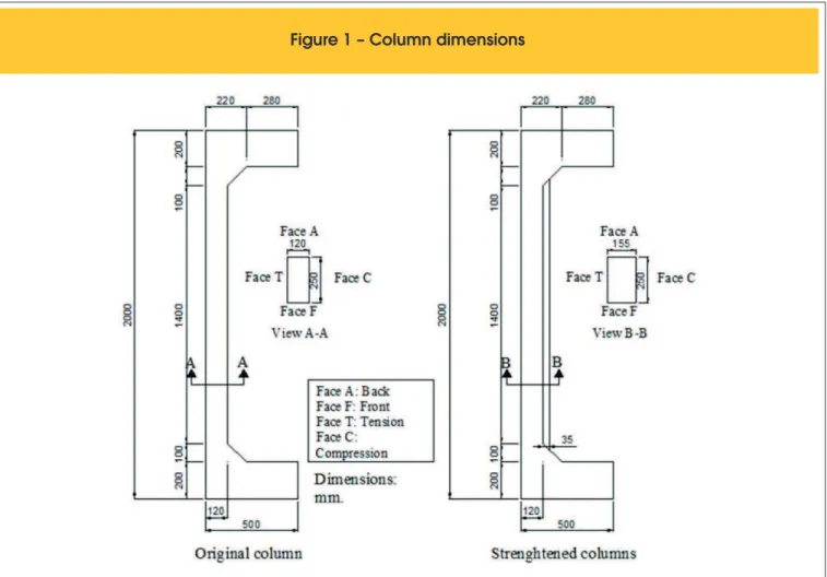
Figure 1 shows column cross sectional dimensions. The columns were built such that two corbels, one at the base and another at the top, allowed for the application of a vertical force with an
eccentric-ity that will provide bending moment at the column mid-length and the column will be under compression and one-axis bending. After strengthening, the smaller cross section dimension was increased from 120mm to 155 mm due to addition of a 35 mm concrete layer. Wedge bolts were placed but no additional steel reinforcement was added to the column.
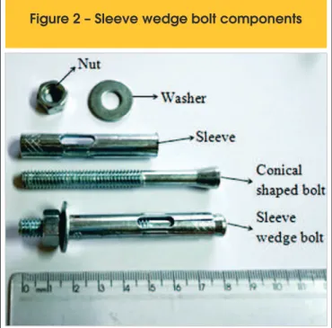
To avoid detachment of the new concrete layer, sleeve wedge bolts with 8 mm nominal diameter and 80 mm effective length were used. The wedge bolt comes complete with conical bolt, jacket, washer and nut as shown in Figure 2. This type of bolt was chosen to continue the study initiated by SAHB (2008) [4].
Column longitudinal steel reinforcement consisted of 4 rebars of 10 mm nominal diameter (As = 314 mm2). Transverse steel reinforce-ment consisted of 5 mm diameter hoops placed every 100mm at column mid-length and spaced every 50mm near column ends as illustrated in Figure 3. Concrete cover of 25 mm followed prescrip-tions in Brazilian Code NBR 6118:2007 Code [8], considering a weak aggressiveness durability class for columns. Prescriptions in EUROCODE 2 (2007) [9] says that minimum rebar cover should assure effective transmission of bond, protection against corrosion and adequate ire resistance.
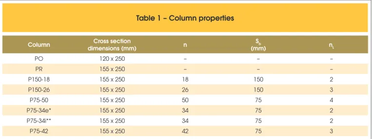
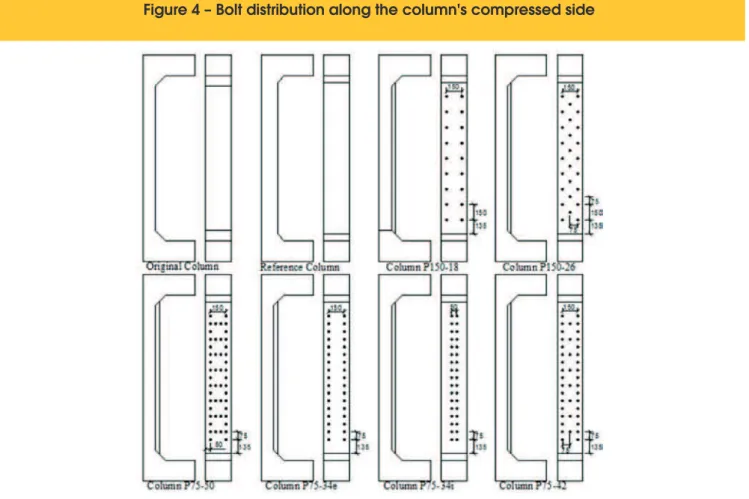
Table 1 shows the column properties such as cross section dimen-sions, amount of bolts, bolt vertical spacing, bolt alignment and positioning and initial vertical load eccentricity for each column. Figure 4 shows bolt distribution for each column. Columns were named following a simple rule:
n PO/PR: Original column and Reference column;
n PX – Y, where X is the vertical bolt spacing in mm and Y is the
amount of bolts.
Column production consisted in the preparation of formwork, as-sembly of reinforcement, concrete casting, curing and formwork removal. Steel formwork was designed to facilitate assembly, re-moval and reuse. Plastic rebar spacers were used to position the reinforcement in the formwork and guarantee a 25 mm rebar cover. Approximately 50 days after casting, the jacket was cast. Prepa-ration for casting the strengthened concrete cover included the
Table 1 – Column properties
Column Cross section
dimensions (mm) n
Sb
(mm) nL
PO 120 x 250 – – –
PR 155 x 250 – – –
P150-18 155 x 250 18 150 2
P150-26 155 x 250 26 150 3
P75-50 155 x 250 50 75 4
P75-34e* 155 x 250 34 75 2
P75-34i** 155 x 250 34 75 2
P75-42 155 x 250 42 75 3
n = amount of bolts; sb = vertical bolt spacing; nL = amount of bolt lines;
einic. = initial load eccentricity: 60 mm for the original column and 42,5 mm for all others; * subscript e = bolts with two external lines;
following steps: drilling holes for bolt ixation, hydro jetting the old concrete surface, bolt ixation.
Bolt length was 80 mm. The bolts were placed in holes 65 mm deep inside the concrete substrate using a large hammer, so 15 mm of the bolt’s length would be positioned inside the new con-crete layer. This positioning was used to guarantee a 20 mm rebar cover as prescribed by Brazilian code NBR 6118:2007 [8], in item 7.4.7.4, that allows a 20 mm nominal rebar cover for columns un-der conditions of durability class I aggressiveness. See Figure 5 for bolt placing details. A wrench was used for tightening the bolt’s
nut. No other structural adhesive material was used for attaching the bolt to the concrete substrate and the device was ixated purely by mechanical anchorage.
2.2 Instrumentation
Steel reinforcement was assembled at the Structural Laboratory of the School of Civil Engineering of the Federal University of Goiás. Steel rebars of the same fabrication lot were used to avoid material properties differences. Longitudinal rebars were numbered 1 to 4: rebars
num-Figure 4 – Bolt distribution along the column's compressed side
93
IBRACON Structures and Materials Journal • 2015 • vol. 8 • nº 2
bered 1 and 2 were positioned at the compressive face and rebars 3 and 4 were positioned at the tension face. Eight electrical strain gauges were attached to rebars at column mid-height to monitor longitudinal reinforcement strain as shown in Figure 6. Previously, mechanical prop-erties of the steel were determined by direct tension test. These tests indicate a yield strain εy of 2,78 mm/m. Concrete strains were measured also at column mid-height by four concrete strain gauges placed on the most compressed face as shown in Figure 6.
Horizontal and vertical displacements were measured by digital displacement indicators as shown in Figure 7. Indicators had a 0,01 mm precision and a 50 mm gauge length. Indicator installa-tion procedure consisted on mounting a ixed device on a vertical support placed behind the column (see igure 7) and the indicator cursor was placed on small metal plates glued to the column’s sur-face. Indicators were removed prior to rupture to avoid equipment
Figure 6 – Strain gauge positioning
a) reinforcement strains, b) concrete strains
A
B
Figure 7 – Positioning of digital
displacement indicators
damage. A complementary reading of mid-height displacement (same height as digital indicator R3 was placed) was taken using a standard measuring tape and it was used to measure horizontal mid-height displacements after removal of the digital indicators.
2.3 Column testing
Figure 8 presents the test setup which is basically the column
attached to a steel frame on a reaction slab. Vertical load ap-plication was done using a hydraulic jack with a 1500 kN capac-ity attached to a manual hydraulic pump. The hydraulic jack was placed under the column on the reaction slab. For better load measurement, two 1500 kN capacity load cells were placed at the column’s top and bottom. The load cells were attached to individual load digital indicators.
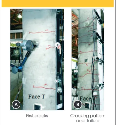
Cracking was observed and cracking patterns were registered throughout the test. Figure 9 shows cracking patters marked with a black magic marker for column P75-50. Initial cracking was ob-served at the 200kN load stage.
3. Results and discussion
3.1 Ultimate loads
Table 2 shows ultimate loads and concrete compressive strength on testing day for the concrete substrate and the new concrete layer.
The ultimate load for the monolithic reference column (PR) was 542,2 kN and the other columns did not reach such load capacity. This load is 3,28 times larger than the one obtained by the original column (PO). Column P150-18 obtains the closest ultimate load to the reference column PR: 84% of PR’s ultimate load, and column P75-42 had the worst performance: 68% of PR’s ultimate load. Still the worst performance showed a load capacity increase of 190% with respect to the original column (PO) ultimate load capacity. Columns P150-18 and P150-26 had the same vertical bolt spacing, but column P150-26 had 8 more bolts. Unexpectedly, column P150-18’s ultimate load was only 2,4% higher than column P150-26’s ultimate load. Comparing columns with the same vertical bolt spacing of 75mm, the column with the high-est amount of bolts (P75-50) had the highhigh-est ultimate load. Table 2 shows that the pillar with bolts internally (P75-34i, Pu = 421,6 kN) had a higher breaking load to its similar with the connectors placed further apart from each other (P75-34e, Pu = 401,2 kN).
Figure 9 – Cracking patterns in column P75-50
A
B
First cracks Cracking pattern
near failure
Table 2 – Concrete compressive strength at testing day and ultimate loads
Column fc
sub
(MPa) / age
fcref
(MPa) / age
Fult
(kN) Fult / FPR Fult / FPO Mode of failure
PO 41,9 / 90 days – 126,7 0,23 – YS/CC
PR 41,3 / 80 days – 542,2 – 4,30 CC
P150-18 41,4 / 83 days 39,7 / 31days 453,2 0,84 3,58 DC
P150-26 41,5 / 95 days 40,1 / 33days 442,5 0,82 3,49 DC
P75-50 42,2 /95 days 42,4 / 46days 422,1 0,78 3,33 DC
P75-34e 42,6 / 102 days 43,4 / 53days 401,2 0,74 3,17 DC
P75-34i 42,5 / 100 days 43,1 / 51days 421,6 0,78 3,33 DC
P75-42 42,7 / 105 days 43,7 / 55days 367,8 0,68 2,90 DC
fcsub : compressive strength of the concrete substrate; f
c
ref : compressive strength of the new concrete layer;
Fult: Ultimate Column Load; PR: Reference Column; PO: Original Column
95
IBRACON Structures and Materials Journal • 2015 • vol. 8 • nº 2
3.2 Horizontal column displacement
Figure 10 show typical column displacements along column height and digital indicator readings are not the same for symmetrical in-dicator positioning (inin-dicators R2-R4 and R1-R5). This is due to the test setup that contributes to a non-symmetry situation. The setup
is statically symmetrical, but kinetically it is not since the vertical load application is at the bottom of the column, and hence, the reaction is at the top or the superior end of the column. The bottom of the column moves as load is applied, but the top does not move. Figure 10 shows column displacements for each digital indicator placed on the tension face, namely indicators R1 to R5, at the 300
2 A statistical method of analysis of variance (ANOVA) was made using the software Statistic 6.0 da Statsoft®. The values of F
calculados (Fcal) were compared with the tabulated values (Ftab) a
signiicance level of 5%. The value of Ftab is equal to Fα=0,05 (ν1 e ν2) where ν1 e ν2 is the degrees of freedom of the evaluated effect and of the residuals.
Figure 10 – Horizontal displacement on face T along column height at 300 kN load
kN loading stage. The maximum horizontal displacements were at column mid-height (indicator R3) as expected. The igure shows that the strengthened columns showed greater horizontal displace-ments when compared to the ones obtained by the reference col-umn PR at the 300kN loading stage, except for colcol-umn P75-34i that had similar displacements to the reference column. The
ulti-mate column load for the original column PO was 126,7 kN, which is lower than the 300 kN load and, hence, column PO’s displace-ments are not shown in this igure.
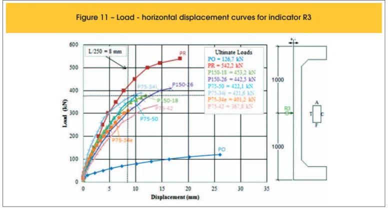
Column displacements at mid-height (indicator R3 readings) for all columns are shown in Figure 11 for all loading stages until rupture. All strengthened columns had less stiffness than column
Figure 12 – Load-strain curves for longitudinal steel rebars located on the column's tension face
97
IBRACON Structures and Materials Journal • 2015 • vol. 8 • nº 2
PR’s stiffness, indicating the strengthened columns had a larger displacement at the same loading stage. This should be consid-ered when designing a strengthened column using with this re-pairing technique.
Although Brazilian code NBR 6118:2007 [8] does not specify a limit value for column displacement at service loads, in this study, a limit of L/250 was adopted based on the code’s limit for visual acceptance in beams. Since column height L was equal to 2000 mm, the displacement limit would be 8mm. This limit should not be surpassed at service loading. To estimate the service load, col-umn PR’s ultimate load was divided by 1,4, which approximately corresponds to a load safety factor adopted in structural design. Thus, the service load for column PR would be 387,3 kN, and the
displacement at this load is equal to 7,3 mm, which is less than the 8mm limit.
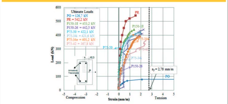
3.3 Tension reinforcement
To analyze longitudinal steel deformations, as those shown in Figure 12, strain gauge readings with highest strains were used. Column PO was still the only one that yielded, surpassing the yield strain of 2,78 mm/m. Tension reinforcement in column PO reached yielding at a load of 90 kN, approximately 71% of ultimate load. Maximum steel strains in other columns were between 1,35mm/m for column P75-34e and 2,25mm/m for column P150-26 and yield-ing did not occur.
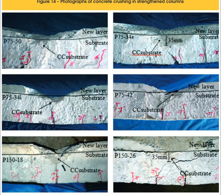
Figure 14 – Photographs of concrete crushing in strengthened columns
3.4 Concrete strains
Figure 13 shows load versus concrete strain curves. Brazilian Code NBR6118 [8] speciies an ultimate concrete strain of 3,5 mm/m for lexure and a an ultimate strain of 2,0 mm/m for pure compression. Since the columns were in compression and one-axis bending, the ACI Code 318M-02 [10] value of 3,0 mm/m was chosen for the ultimate concrete strain and this value is between the two values speciied by the Brazilian code. Figure 14 shows that the highest concrete strains on the column face with most compression were close to the ultimate strain value for all columns.
Strengthened column P150-18, with the smallest number of bolts, had the smallest ultimate concrete strain and the highest strains occurred in columns P75-50 e P150-26. Reference column PR had an ultimate concrete strain of 2,09 mm/m.
Column PO, with a smaller cross section, had the highest concrete strains at a given load level. At rupture, concrete strain reached a value of 2,86 mm/m, close to code value of 3,0 mm/m, and con-crete crushing could be observed during the test, as shown in Fig-ure 15.
3.5 Modes of failure
Failure modes for all columns are listed in Table 2 and Figures 14, 15 and 16 show photographs of the cross section of some columns at rupture.
Original column PO failed by yielding of the longitudinal tension steel reinforcement followed by crushing of the compressed con-crete. Reference column PR failed by concrete crushing, but the tension steel did not yield. This was conirmed by strain gauge readings in the concrete and steel.
All strengthened columns showed detachment of the new concrete layer at rupture followed by concrete crushing of the substrate as illus-trated in Figure 14. After detachment of the concrete layer, crushing of concrete substrate reached its greatest depth in columns P75-34e e P150-26 and a depth of 35mm was measured from the interface. The other strengthened columns had smaller crushing depths.
Figures 15 and 16 show cracking patterns for columns PO and P75-50 at rupture and similar patterns were observed in the other columns. Concrete crushing on the most compressed column face and crack opening on the tension side (Face T) was observed in the original column PO. Detachment of the new concrete layer and crack opening on Face T (tension side) was observed in column P75-50 as well as in all other strengthened columns.
4. Conclusions
n Although without statistical signiicance due to the small
num-ber of specimens, results indicate the amount and position of the bolts can inluence the resistance of the strengthened col-umns. Unexpectedly, the column with the smallest number of bolts (column P150-18) had the highest ultimate load. Analyz-ing the two columns with the same number of bolts (columns P75-34i and P75-34e), positioning the bolts internally was more effective than externally. This suggests that bolt eficiency can be related to its position in the concrete layer.
n Shear failure in the bolts did not occur. Bolts presented good
behavior in all cases.
n Yielding occurred only in the longitudinal reinforcement of the
original column PO. Applied load eccentricity was reduced due to a cross section increase as a new concrete layer was added in the strengthened columns, causing smaller stresses due to bending moment, so yielding of the longitudinal reinforcement on the tension face did not occur.
Figure 15 – Photograph of original column
at failure
99
IBRACON Structures and Materials Journal • 2015 • vol. 8 • nº 2
n All strengthened columns had a premature failure due to
the detachment of the new concrete layer from the concrete substrate. Crushing of the concrete substrate, as shown in Figure 14, occurred after detachment, once the new con-crete layer no longer contributed to the column’s resistance and all load was transferred to the concrete substrate. Con-crete crushing occurred at rupture in the reference column and in the original column.
5. Acknowledgements
The authors wish to thank CAPES – Coordenação de Aper-feiçoamento de Pessoal de Nível Superior, and CNPq – Con-selho Nacional de Desenvolvimento Cientíico e Tecnológico for the inancial support,. In addition, special thanks to REALMIX for providing the self-compacting concrete and to Carlos Campos for providing the equipment necessary for preparation of the con-crete substrate.
6. References
[01] SOUZA, R.H.F. (1990). Análise do Comportamento de vigas de betão armado reforçadas à lexão e ao esforço trans-verso. Lisboa, Tese (Doutorado) - Universidade Técnica de Lisboa.
[02] MORENO Jr., R. “Estudo de fatores que afetam a aderência da argamassa de reparo para estruturas de concreto”. Dis-sertação (Mestrado) – Escola Politécnica, Universidade de São Paulo. São Paulo, 2002, 202p.
[03] OMAR, M. Y. M. Análise Experimental de Pilares de Con-creto Armado Reforçados com ConCon-creto Auto-adensável (CAA) – Volume 3, p.271, Revista Ibracon de Estruturas e Materiais, 2010.
[04] SAHB, K. F. P. Análise experimental de pilares de concreto armado submetidos à lexo-compressão, reforçados com concreto auto-adensável e chumbadores. 2008. 226p. Dissertação (Mestrado) – Universidade Federal de Goiás, Goiás, 2008.
[05] NASCIMENTO, P. P. M. Análise Experimental de Pilares de Concreto Armado Reforçados com Concreto Auto-Adensáv-el e Conectores – Volume 5, p.305-315, Revista Ibracon de Estruturas e Materiais, 2012.
[06] MARQUES, M. G. (2013). Análise do comportamento de pilares de concreto armado reforçados com chumbadores e concreto auto adensável – Titulo provisório. Dissertação (Mestrado em andamento) - Escola de Engenharia Civil, Universidade Federal de Goiás. Goiânia.
[07] FERREIRA, D. B, Análise Experimental de Pilares de Con-creto Armado, Reforçados com ConCon-creto Autoadensável. – Revista Eletrônica de Engenharia Civil - Escola de Engen-haria Civil, Universidade Federal de Goiás. Goiânia, 2013. [08] ABNT NBR 6118: Projeto de Estruturas de Concreto –
Pro-cedimento. Rio de Janeiro, 2003.
[09] EUROCODE 2: Design of Concrete Structures – General Rules and Rules for Buildings.
[10] Technical Committee – ENV 2001-1-3. Brussels, 2007. [11] ACI COMMITTEE 318. Building Code Requirements for

![Figure 13 shows load versus concrete strain curves. Brazilian Code NBR6118 [8] speciies an ultimate concrete strain of 3,5 mm/m for lexure and a an ultimate strain of 2,0 mm/m for pure compression](https://thumb-eu.123doks.com/thumbv2/123dok_br/18860919.417913/11.892.67.435.182.609/figure-concrete-brazilian-speciies-ultimate-concrete-ultimate-compression.webp)
