Abstract—A full-wave analytical method using the addition theorems and Hertzian potential functions are used to compute the radar cross section of a sphere coated by several layers composed of common materials and metamaterials. The minimization and maximization of radar cross section of a perfectly electric conductor sphere with such coatings are realized in a frequency band-width and in a wide interval of angles. One of the novelities of this contribution is, taking into dispersion relations of physically realizable metamaterials. So that the optimization procedure for RCS reduction is applied due to the coefficients describing dispersion characteristics. The method of least square is used for the design of a class of radar absorbing materials. The minimization of the error functions are performed by the combination of genetic algorithm and conjugate gradient method. It is shown that the proposed method of computation of radar cross section and its extremization effectively leads to the design of dispersive and isotropic metamaterials for the realization of radar absorbing materials.
Index Terms—Metamaterial; Multilayer; Perfect Electric Conductor; Radar
Cross Section.
I. INTRODUCTION
In this paper we consider a multilayer coating composed of metamaterials (MTMs) [1-5] on a dielectric or conducting sphere for the purpose of ultra wide band reduction of its radar cross section
(RCS) [6-7]. Application of common materials to the coatings of objects does not by themselves alone provide an ideal method for the reduction of RCS. On the other hand, combination of common
materials and metamaterials provide an effective means for the reduction of RCS.
Here metamaterials are used as radar absorbing materials (RAMs) [8-10], which may be used for
the reduction of RCS, and also wall coatings inside anechoic chambers, antenna coatings for side lobe level reduction, and shielding against electromagnetic interference in high frequency circuits.
Dispersive models of metamaterials, such as Lorentz, Drude and resonance models are used for the analysis and design of MTM multilayer coatings [11-12] which are thus physically realizable, because they satisfy the causality relations (as the Cramers-Kronig relations).
Ultra Wide Band Radar Cross Section
Reduction of a Perfectly Electric Conductor
Sphere by the Application of Multilayer
Metamaterial Coatings
Homayoon Oraizi1, AliAbdolali2, Mahmoud Fallah3
1-3
RCS is a complicated function of the geometrical dimensions, physical characteristics and dispersion relations of the target and its layered coatings. The parameters and variables in the geometrical, physical and dispersive properties of an object actually provide several degrees of
freedom to achieve the desirable features of RCS, such as its minimization or maximization.
We consider spherical geometries, because a sphere may be considered as a canonical shape for
modeling some parts of complex bodies. Since multilayer coating have more potential for RCS reduction with respect to single-layer coatings (with the same thickness), we have developed our
method for multilayer structures. The core sphere may be made of any material such as perfect electric conductor or dielectric material.
The analysis methods for the electromagnetic wave scattering from multilayer spherical structures may be divided into analytic, approximate and numerical methods. We consider the incidence of a
plane wave and its full-wave analysis using the addition theorems and the spherical Eigen-function expansions. Forward and backward traveling waves are considered in each layer of the coating [13].
It should be noted that if an object is much larger than a wavelength, then it may be modeled as a planar structure and the related methods may be used. Furthermore, the physical optics
approximations (PO) may also be applied. However, the scattering of electromagnetic waves from an object with dimensions comparable to a wavelength, is a more complicated problem which is the subject of the present paper.
Metamaterials were first considered theoretically by Veselago [14] and were then experimentally fabricated by Pendry and Smith [15-16]. They are usually categorized as double positive (DPS),
double negative (DNG), epsilon negative (ENG), mu negative (MNG), double zero (DZR) [17], epsilon zero (EZR) and mu zero (MZR), depending on whether the real parts of and are positive,
negative or zero. The sign of real and imaginary parts of the propagation constant () and
characteristic impedance () of MTMs should be properly selected, and a short discussion of it is
also given in [18]. The interaction of dispersive metamaterial multilayer spherical structures with an
incident wave is quite a complicated physical phenomenon. We have taken some clues from the multilayer planar structures composed of various combinations of DPS, DNG, ENG and MNG
metamaterials for the reduction of wave reflection as discussed in [18] to reduce the RCS of spherical structures. The optimization method composed of GA and CG algorithms are used to obtain the global
minimum point of a very complicated error function having many local minima for the design goal of minimization of RCS. Previously, we have analyzed the one dimensional problems of multilayer
planar structures [5, 11, 17, and 18]. We then treated the 2-dimensional problem of multilayer cylindrical structures [10]. We now consider the 3-dimensional problem of multilayer spherical
structure for the objective of extremization of RCS by the established combination of common materials and metamaterials for the layered coatings and inclusion of dispersion relations. Since the
phase cancellations in the cases that both common materials and metamaterials are used in combination. Furthermore, the dispersive materials possess complexand, where their imaginary
parts are negative leading to their losses. These two mechanisms lead to effective reduction of RCS.
II. FORMULATION OF THE PROBLEM
The frequency selective surfaces which transmit the visible light have many applications such as the transparent antennas and the design of electromagnetic shield windows.
Consider a sphere of radius r1coated by several concentric spherical coatings of radiiri ,i 2,3,... as shown in Fig.1. The inner sphere may be composed of a perfectly electric conductor, dielectric material or metamaterial (MTM). The coating layers are made of homogeneous and isotropic
materials or MTMs [19-20].
l
r
2
r
1
r y
PEC
z r x
Incident
1 1
2 2
l
l
N
N
... ... 1
1 N
N
N
r
1 N
r Plane Wave
z x
y r
Fig.1: The geometry of the multilayer spherical structure
We express the electromagnetic fields in terms of radial components of electric and magnetic vector
Hertzian potentials, namely e 1r andˆ m 2rˆ for TE E( r 0)and TM H( r 0)modes [13]. In this manner, the Hertzian potentials satisfy the scalar wave equations,
(1)
2 2
( k ) i 0 , i 1, 2
(2)
2 2 1 2 1 2 2 2 1 2 1 2 2 2 2 2 2 1 2 1 2 2 1 1 1 1 r r r sin j H sin j r r r E r r sin r j H j r r sin r E r k r r H r k r r E r rNow, consider a plane wave incident on the spherical structure
(3) 1 1 1 ˆ 1 ˆ N N jk z inc jk z inc N e x
H e y
The radial components of fields are:
(4) 1 1 1 ˆ . 1 ˆ . N N jk rCos ir inc jk rCos ir inc N
r e sin cos
H r e sin sin
We assume the time dependenceej t ,which should be considered for the selection of right signs of&. The boundary conditions are the continuity of tangential components of electric and
magnetic fields, namely:
(5)
, 1, , 1,
, 1, , 1,
,
,
i i i i
i i i i
The expressions of boundary conditions will be functions of both 1and2, as Equations 2 show.
However, we prefer the boundary conditions to be functions of only one Hertzian potential, namely
1
or2. We may obtain such relations by a linear combination of the fields.
Consequently, the continuity of the following quantities are arrived at the boundaries:
(6)
(( 1 2
1 2
( ) ( )
, , ,
r r
r r
))
(7)
(1) (1)
( 1)1 1
0 0
(2) (2)
( 1)2 1
0 0
ˆ ( ) ( )
ˆ ( ) ( )
n
i m
N n N n mn mn
n m
n
i m
N n N n mn mn
n m
J k r cos A cosm B sinm
J k r cos A cosm B sinm
Where the surrounding medium in free space is denoted by i N 1 and
(8)
1
( 1)1 2 1
1 1
1
( 1)2 2 1
1
1 1
1 ˆ
( ) ( )
1 ˆ
( ) ( ) sin
i
N n n N n
n N
i
N n n N n
n
N N
r A J k r cos cos
k
r A J k r cos
k
1 (1) 1( ) (2 1)
( 1)
n
n n
j n
where A A
n n
The scattered field is given by the following Hertzian potential with superscript s instead of i :
(9)
(2) 1
( 1)1 2 1
1 1
(2) 1
( 1)2 2 1
1 1 1 1 ˆ ( ) ( ) 1 ˆ ( ) ( ) s
N n n n N n
n N s
N n n n N n
n
N N
r A a k r cos cos k
r A b k r cos sin k
In mn, the first subscript m refers to the layer and the second one refers to the moden1, 2.
We now express the Hertzian potentials in the spherical layers by the sum of spherical Bessel and Hankle functions as:
(10) 1 1 2 1 1 2 2 1
1 ˆ ˆ
( ) ( ) ( )
1 ˆ ˆ
' ( ) ' ( ) ( ) sin
l n n n l n n l n
n l
l n n n l n n l n
n l l
r A c J k r d Y k r cos cos
k
r A c J k r d Y k r cos
k
Inside the inner sphere, the functionYˆn(k rl ) is deleted, because it is singular at r 0.
We then consider the case of a PEC sphere. The tangential electric field on the surface of sphere should be zero.
(11)
0 r r 0 r r r r 0 r r E r r E 1 1 1 1 l2 l1Specifically, for (11) we have
(12)
' '
1 1 1 1
' '
1 1 1 1
ˆ ( ) ˆ ( ) 0
ˆ ( ) ˆ ( ) 0
n n n n
n n n n
c J k r d Y k r c J k r d Y k r
We use the following identity
(13)
1
ˆn( ) ˆn ( ) n ˆn( )
J kr kJ kr J kr
r r
In (12) to obtain
(14)
1 1 1 1 1 1
1 1 1 1 1 1
' '
1 1 1 1
ˆ ( ) ˆ ( )
ˆ ( ) ˆ ( ) 0
ˆ ( ) ˆ ( ) 0
n n n
n n n
n n n n
c k r J k r nJ k r
d k rY k r nY k r
c J k r d Y k r
The continuity of tangential fields at the boundary between layers land l 1 are
(15)
1
( 1)11 1
1 1 ( 1)1
1 1
l l
l l
l l l l
l l
r r
r r r r
r r
r r r r
Combining (10) and the first relation in (15), we have
(16)
1 ' '
1 1 1
1
ˆ ( ) ˆ ( )
ˆ' ( ) ˆ' ( )
l n n l l n n l l
l n n l l n n l l
k e J k r f Y k r
k c J k r d Y k r
For the second relation in (15), we have
(17)
1 1
1
1 ˆ ˆ
( ) ( )
1 ˆ ˆ
( ) ( ) 0
n n l l n n l l
l
n n l l n n l l
l
c J k r d Y k r
e J k r f Y k r
Finally, for the boundary between the outer coating and the free space, we have
(18)
( 1)1 ( 1)1 1
1 1
1 ( 1)1 ( 1)1 1
1 1
i s
N N N
N N
i s
N N N N N
N N
r r
r r r r
r r
r r r r
Using (8), (9) and (10), we have
(19)
' (2)
1 1 1 1
1
' '
1 1
(2)
1 1 1 1
1
1 1
1 ˆ ˆ
( ) '( )
1 ˆ ˆ
( ) ( )
1 ˆ ˆ
( ) ( )
1 ˆ ˆ
( ) ( )
n N N n n N N
N
n n N N n n N N
N
n N N n n N N
N
n n N N n n N N
N
J k r a H k r
k
p J k r q Y k r
k
J k r a H k r
p J k r q Y k r
(20)
' '
1 1 1 1
' ' ' '
1 2 1 2 1 2 2 1 2 2
2 2
1 2 1 2 2 2
1 1 2 2
' ' ' '
1 1 1 1 1 1
ˆ( ) ˆ( ) 0 0 0 0 0
ˆ( ) ˆ( ) ˆ( ) ˆ( ) 0 0 0
1
1 ˆ 1 ˆ 1 ˆ ˆ
( )
( ) ( ) ( ) 0 0 0
ˆ ˆ ˆ ˆ
0 0 ( ) ( ) ( ) ( ) 0
n n
n n n n
n
n n n
n l l n l l l n l l l n l l J k r Y k r
J k r Y k r m J k r m Y k r
Y k r J k r Y k r J k r
J k r Y k r m J k r m Y k r
1 1 1 1 1 1
1 1
' ' (2) '
1 1 1 1
(2)
1 1 1 1
1
1 ˆ 1 ˆ 1 ˆ 1 ˆ
( ) ( ) ( ) ( )
0 0 0
ˆ ˆ ˆ
0 0 0 0 ( ) ( ) ( )
1 ˆ 1 ˆ 1 ˆ
0 0 0 0 ( ) ( ) ( )
n l l n l l n l l n l l
l l l l
n N N n N N N n N N
n N N n N N n N N
N N N
J k r Y k r J k r Y k r
J k r Y k r m H k r
J k r Y k r H k r
' 1 1 1 1 1 0 0 0 0 0
ˆ ( )
1 ˆ ( ) n n n n n
N n N N n
n N N n N c d e f p
m J k r q
J k r a Where 1 l l l k m k .
For the magnetic Hertzian potential, in the first line, the derivatives are replaced by the functions,
is replaced by and1 1 1
l l l
l
l l l
k m k
With the large argument relations for the spherical Hankle functions, we have
(21)
1
1
1 1
( 1)1 2
1 1
1 1
( 1)2 2
1 1 1 ( ) ( ) N N jk r s n
N n n n
n N
jk r
s n
N n n n
n
N N
e
r j A a cos cos k
e
r j A b cos sin k
(22)
( 1)
1 ( 1) , 1, 2s s
N i N N i
r jk i
r
The field components are
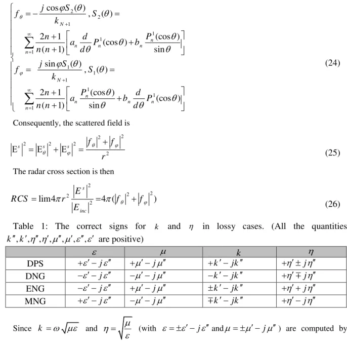
(24) 2 2 1 1 1 1 1 1 1 1 1 1
cos ( )
, ( )
(cos )
2 1
(cos )
( 1) sin
sin ( )
, ( )
(cos )
2 1
(cos )
( 1) sin
N
n
n n n
n
N
n
n n n
n j S f S k P n d
a P b
n n d j S
f S
k
P
n d
a b P
n n d
Consequently, the scattered field is
(25)
2 2
2 2 2
2
s s s f f
r
The radar cross section is then
(26) 2 2 2 2 2
lim4 4 ( )
s
inc E
RCS r f f
E
Table 1: The correct signs for k and in lossy cases. (All the quantities
, , , , , , ,
k k are positive)
k j
k jk
j j DPS j
k jk
j j DNG j
k jk
j j ENG j
k jk j j MNG
Since k and
(with jand j) are computed by
square roots, they are double valued. They also depend on the selection of time dependence, here as
exp(jkr j t ). The selection of correct signs for the complex quantities k k jkand
j
are given in Table 1 [11].
Various types of materials and metamaterials are used for radar absorbing materials (RAMs). These
materials may be lossy or lossless and they may be considered nondispersive or frequency dispersive. The various dispersion models for materials and metamaterials are given in Table 2 [20-21]. Materials
are usually divided into seven categories: namely, DPS(Re( ) 0 & Re( ) 0 ),
DNG(Re( ) 0 & Re( ) 0 ), ENG(Re( ) 0 & Re( ) 0 ), MNG(Re( ) 0 & Re( ) 0 ) ,
Table 2: Dispersion relations for common material and metamaterial media
Permeability model Permittivity model
Class of materials
r
r j i
f f
Lossy dielectric
r i
b j
f f
r
Lossy magnetic
2 m
2 2
( f )
m m
m jf f
f f
r
Relaxation-type magnetic
μ 1
2 ep 2
e
f 1 -
f j f γ
Drude mode (Rods only)
2 2
mp mo
2 2
mo m
f f
μ 1
f f j f γ
1
Lorentz model (Rings only)
2 2
mp mo
2 2
mo m
f f
μ 1
f f j f γ
2 ep 2
e
f 1 -
f j f γ
Drude & Lorentz (Rods & Rings)
2
2 2
mo m
μ 1
f f j f γ
Ff
r j i
Resonance
2
2 2
mo m
μ 1
f f j f γ
Ff
2 ep 2
e
f 1 -
f j f γ
Drude & Resonance
The main objective of the paper is to determine the parameters of dispersion relations for the extremization of RCS from spherical structures. We have not deal with the microscopic nature of metamaterials and the methods of their realizations, even though such a topic is discussed in the
literature [18].
For the design of multilayer spherical coatings, an error function is constructed for the realization of
a specified value of RCS [22].
(27)
2
ij j=1 i=1
Error Function W RCS( ,i j) ij
f
n n
f C
whereCij are the specified RCS, Wij are weighting functions and i,j indicate the frequency and the observation angle in the specified frequency band and observation angle interval divided into
n &f ndiscrete frequencies and angles respectively. The error is a function of the spherical shell radii(r )i , and the parameters of the dispersion relations.
For the minimization of the error function, we use the combination of the genetic algorithm (GA) [23-24] and conjugate gradient method (CG) [25] to benefit from their advantages and avoid their
disadvantages. The minimization procedure starts by GA which is a global extremum seeking algorithm and does not depend on the initial values of the variables, but it is quite time consuming.
seeking algorithm and depends on the initial values of variables, but it is quite fast. The above cycle is repeated until the global minimum of the error is hopefully located [26].
III. NUMERICAL RESULTS
We study the scattering properties of a sphere covered by multilayer spherical shells
through several examples here.
We use dispersion relations for and in all of our examples. However, in some
examples we use nondispersive situations along the dispersive cases for comparison and
emphasis of the main differences. We observe that the dispersive cases have far better results
than the non-dispersive cases.
We have selected distinct objectives for each example, which span over different
characteristics, such as minimization of RCS, maximization of RCS, achievement of some
specified pattern, single or multilayered spherical shapes, use of common materials,
metamaterials or their combinations, inclusion of various dispersion relations and
nondispersive materials.
We have used an exact analytical method without any approximation, which is the
generalization of the addition theorem and Mie method for the multilayer spherical structures.
Our computer programs are exact, whereas the commercial simulations softwares (such as
HFSS and CST) may encounter difficulties at critical points, say 0, as we have observed.
Any slight discrepancy between our results and those of the commercial softwares is certainly
due to their approximations, because our formulation and results are analytically correct.
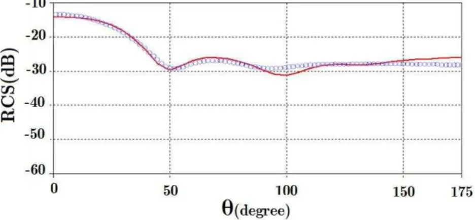
Example 1. RCS of a PEC sphere
Consider a PEC sphere of radius r0 = 3cm under a plane wave incidence at the
frequencyf = 18GHz . Its RCS is computed by our algorithm and obtained by the CST
Fig 2: RCS of a PEC sphere (with radius 3 cm) as a function of azimuth
angle
(
0° £ £q 180°)
in planej
=
0
. The values obtained by CST and the proposed algorithm are indicated by solid line and circles, respectively.Example 2. RCS of a PEC sphere coated by a metamaterial coating
Consider a PEC sphere of radius
0 1
r = cm with a metamaterial spherical coating of
thickness 1cm and characteristics e = - 5 , m= - 3under a plane wave incidence
atf = 10GHz. Its RCS is computed by our algorithm and obtained by the CST software.
They are drawn in Fig.3 versus q.
Fig 3: RCS of a PEC sphere (with radius 1 cm) with an MTM coating with thickness 1 cm and parameters e= - 5,m= - 3
in the plane
j
=
0
as a function of azimuth angle(
0° £ £q 180°)
. The values obtained by CST and the proposed algorithm areindicated by solid line and circles, respectively.
The above two examples serve to verify our algorithm for the computation of RCS of
multilayer spherical structures. Our computer program is based on an exact method for the
dispersive material or metamaterial media. However, the CST software may not have such
accuracy, particularly at 0,180. Also, simulation by CST is very time consuming. We
have compared our program with the CST simulation at a single frequency (as a
nondispersive case) for some verification of our code. Observe that the agreement between
the results of our program and those of the CST simulation are good at all angles( ) except
the critical ones 0,180. Our results are also verified by those in the literature [13].
Example 3. Reduction of RCS due to a PEC sphere with a coating of DPS material
Consider a PEC sphere of radius r0 = 5cm. We compute its monostatic (or backward
0
q= ) RCS in the frequency band D =f 1- 10GHz and draw it in Fig. 4.
1 2 3 4 5 6 7 8 9 10
-80 -70 -60 -50 -40 -30 -20 -10 0 10
Frequency (GHz)
R
C
S
(
d
B
)
Without coating Non-Dispersive Lossy Dielectric Lossy Magnetic Relaxation Type
Fig 4: RCS-vs-frequency of a PEC sphere (of radius 5 cm) with a single layer of coating composed of dispersive and nondispersive right-handed materials.
Then we consider the PEC sphere coated by a lossy nondispersive and dispersive DPS
material layer. Minimization of RCS by the proposed algorithm is carried out and it is drawn
versus frequency in Fig. 4. The PEC sphere is coated by a spherical layer made of lossy
dielectric, lossy magnetic and relaxation type frequency dispersive and nondispersive plasma
DPS materials (Re( , ) 1& Im( , ) 0 ).
The RCS is minimized by the proposed algorithm with respect to the thickness of coating and
the parameters of its material. Their optimum values are given in Table 3.
The RCSs are drawn versus frequency in Fig. 4. Observe that drastic reduction of RCS is
achieved by the application of a coating on the PEC sphere.
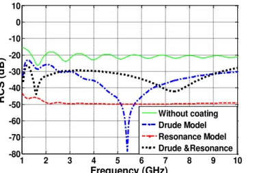
Example 4. Reduction of RCS due to a PEC sphere coated by a layer of metamaterial
Consider the same spherical structure as in example 3, except that the spherical layer
dispersion models. The monostatic RCS is minimized by the proposed algorithm in the band
width D =f 1- 10GHz and drawn in Fig. 5. The corresponding optimum parameters are
given in Table 3. For the Drude dispersion model realized by thin wires (TW), we have
enhanced the weight of middle frequency in the bandwidth. For the resonance model realized
by split ring resonators (SRR), the weight is assumed uniform across the bandwidth. In this
model, both eandm are assumed frequency dependent. Observe that the advantage of
metamaterials is that their dispersion models are adjustable by the variation of their
parameters.
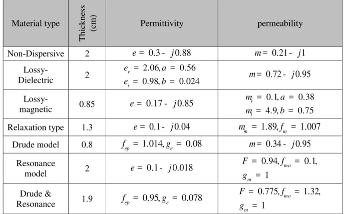
Table 3: The parameters in the dispersion relations and the thickness of MTM coating in examples 3 & 4
permeability Permittivity
Thic
kne
ss
(c
m)
Material type
0.21 j1
m=
-0.3 j0.88
e=
-2 Non-Dispersive
0.72 j0.95
m=
-2.06, 0.56
0.98, 0.024
r
i
e a
e b
= =
= =
2 Lossy
-Dielectric
0.1, 0.38
4.9, 0.75
r
i
m a
m b
= =
= =
0.17 j0.85
e=
-0.85 Lossy
-magnetic
1.89, 1.007
m fm
m = =
0.1 j0.04
e=
-1.3 Relaxation type
0.34 j0.95
m=
-1.014, 0.08
ep e
f = g =
0.8 Drude model
0.94, 0.1,
1 mo
m
F f
g
= =
=
0.1 j0.018
e =
-2 Resonance
model
0.775, 1.32,
1 mo
m
F f
g
= =
=
0.95, 0.078
ep e
f = g =
1.9 Drude &
1 2 3 4 5 6 7 8 9 10 -80
-70 -60 -50 -40 -30 -20 -10 0 10
Frequency (GHz)
R
C
S
(
d
B
)
Without coating Drude Model Resonance Model Drude &Resonance
Fig 5: RCS-vs-frequency of a PEC sphere (of radius 5 cm) with a single layer of coating composed of dispersive and nondispersive MTMs
The optimum designs reported in Figs 4 and 5 are the results of minimization of the error
function in Eq.26, which is actually our design criterion. We have also benefited from the
conclusions of our analysis of the multilayer planar structures [18] for the solution of the
spherical problem.
Example 5. Reduction of backward RCS inside a beam width at a single frequency
Consider a PEC sphere of radius equal to 5cm , coated by a layer of material. Minimization of the backward RCS in the beam-width 0° < j < 360 ,150° ° < q< 180°, leads
to a large thickness of the layer. To decrease the thickness of the required coating, we apply
two layers composed of common materials and metamaterials as the combination of
ENG-DPS double layer. The minimization of RCS in the beam width D =q 30°leads to a drastic
decrease of the overall thickness of the coating equal to 1.25cm. Observe that the
combination of DPS and metamaterials results in the reduction of RCS with effectively
thinner coatings. The characteristics of the resultant ENG and DPS media are as follows:
1
1
0.078 0.19
0.27 0.69
0.56 j
j
thickness cm
e
m
ìï = -
-ïïï = -íï
ï =
ïïî
first layer (ENG):
2
2
1.053 0.74
1.13 0.62
0.69 j
j
thickness cm
e
m
ìï = -
-ïïï = -íï
ï =
ïïî
second layer (DPS):
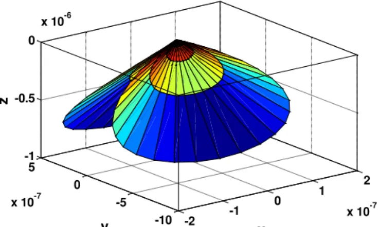
The RCS pattern of this structure atf = 10GHz are drawn in 3-D diagrams in Figs 6 and
figures RCS is shown in the same coordinate system described in Fig. 1 So x, y, z are the
same with the ones in Fig. 1. Distance of every point of RCS pattern surface with a specific
angular direction from the origin of coordinates indicates RCS magnitude in that specific
direction (angle).
-0.2 -0.1
0 0.1 0.2
-0.2 0
0.2-1 0 1 2 3
x y
z
Fig. 7: 3-D diagram of scattering pattern for RCS of a PEC sphere with two layers of coating in the form of DPS-ENG in the range
Example 6. Extremization of bistatic RCS
Consider a PEC sphere of radius 5cm . The minimization of its bistatic RCS (in the
direction
2
p
q = ) at single frequency f = 12GHz, is best achieved not by a single layer of coating, but by two layers. The minimization of its bistatic RCS is achieved by the following
optimum parameters:
1
1
0.52 0.005
0.62 0.97
0.63 j
j
thickness cm
e
m
ìï = -
-ïïï = -íï
ï =
ïïî
first layer (ENG):
-2 -1
0 1 2
x 10-7 -10
-5 0 5
x 10-7 -1 -0.5 0
x 10-6
x y
z
Fig. 6: 3-D diagram of scattering pattern for RCS of a PEC sphere with two layers of
coating in the form of DPS-ENG in the range 0< j < 360 ,150° ° < q< 180°at 10
2
2
0.94 0.26
1.55 0.23
0.84 j
j
thickness cm
e
m
ìï =
-ïïï = -íï
ï =
ïïî
second layer (DPS):
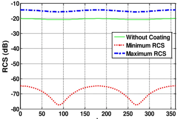
It is drawn versus frequency in Fig.8, wherein it is compared with that of a bare PEC
sphere. Again, the bistatic RCS at
2
p
q= of the PEC sphere is maximized by a DNG-DNG
bilayer coating with the following characteristics.
1
1
1.45 0.003
1.26 0.0015
0.86 j
j
thickness cm
e
m
ìï = -
-ïïï = - -íï
ï =
ïïî
first layer (DNG):
2
2
0.96 0.003
0.96 0.002
0.37 j
j
thickness cm
e
m
ìï = -
-ïïï = - -íï
ï =
ïïî
second layer (DNG):
The resultant RCS is drawn versus frequency in Fig.8, for comparison with the two former
cases.
0 50 100 150 200 250 300 350
-80 -70 -60 -50 -40 -30 -20 -10
R
C
S
(
d
B
) Without Coating
Minimum RCS Maximum RCS
Fig 8: RCS vs. angle j of a PEC sphere (of radius 5 cm) with two layers of coating (once
as DPS-ENG & second as DNG-DNG) in the plane
2
p
q = at f = 12GHzfor the purpose of increasing the bistatic RCS
Example 7. Realization of directive RCS patterns
Suppose we desire to maximize the scattered wave due to a PEC sphere of radius 5cm in the beam width 0° < q< 15° at frequency f = 15GHz or equivalently maximize its forward RCS. The application of proposed algorithm for a DPS-MNG bilayer coating provides the
1
1
0.067 0.63
1.9 0.93
1.5 j
j
thickness cm
e
m
ìï =
-ïïï = -íï
ï =
ïïî
first layer (DPS):
2
2
0.073 0.082
1.91 0.063
1.28 j
j
thickness cm
e
m
ìï =
-ïïï = - -íï
ï =
ïïî
second layer (MNG):
The 3-D diagram of the scattered field pattern of the structure is drawn in Fig.9. RCS
magnitude is shown on the pattern surface with a relevant color. The color of a point on the
surface gives a decent estimate of RCS in its angle: blue points have smaller RCS and red
points have larger RCS. In figure 9, since the wave is incident in –z direction and
optimization is carried out in the angles of 150<theta<180, the extension of RCS pattern is
nearly zero in –z direction and color of the surface is close to blue in this region. By moving
toward +z direction, distance of the pattern surface from the coordinates’ origin increases and
the color of the surface turns to red which shows reduction of RCS in 150<theta<180. Based
on your comment this discussion is added to the paper.
-0.4 -0.2 0
0.2 0.4 -0.5
0 0.5-5
0 5 10 15
x y
z
Fig. 9: 3-D diagram of scattering pattern for RCS of a PEC sphere with two layers of
coating in the form of MNG-DPS in the range 0° < j < 360 ,150° ° < q< 180°at 15
f = GHz
Similarly, the scattered wave in the beam width 0° < q< 15°or equivalently the forward
RCS of the PEC sphere is maximized by the application of a DPS-DNG bilayer coating. Its
characteristics are obtained as
1
1
0.5 0.87
0.06 0.42
0.08 j
j
thickness cm
e
m
ìï =
-ïïï = -íï
ï =
ïïî
2
2
0.9 0.98
1.7 0.65
0.43 j
j
thickness cm
e
m
ìï = -
-ïïï = -íï
ï =
ïïî
second layer (ENG):
The 3-D diagram of its scattered field pattern is drawn in Fig.10. Observe that any RCS
field pattern may be obtained from a PEC sphere by appropriate coatings composed of
various combinations of common materials and metamaterials.
-0.2 -0.1
0 0.1 0.2
-0.2 0
0.2-2 0 2 4
x y
z
Fig. 10: 3-D diagram of scattering pattern for RCS of a PEC sphere with two layers of
coating in the form of ENG-DPS in the range 0° < j < 360 ,150° ° < q< 180°at 15
f = GHz
Example 8. Reduction of RCS due to a PEC sphere in the Ku band by the RH and LH composite media
Suppose it is desired to minimize the RCS of a PEC sphere of radius 10cm in the
frequency band-width Df = 12- 18GHz. After extensive experimentation with several
combinations of material media for bilayer coatings, the following configurations may be
proposed. It is proposed that the first layer be a metamaterial with Drude & resonance
dispersion model and that of the second layer an RH media with a relaxation type dispersion,
namely a DNG-DPS structure. The second case may be a bilayer structure, where the first
layer is a metamaterial media with the Drude dispersion model and the second one with the
Lorentz dispersion model, namely an ENG-MNG structure. The optimum characteristics of
these media are given in Table 4.
The backward RCS of the three cases, namely a bare sphere, one with DNG-DPS bilayer
coating and one with ENG-MNG bilayer coating are minimized and drawn in Fig. 11.
Observe that the RCS has drastically decreased by the application of MTMs and also by two
layers of coatings with noticeably lower thickness than one layer with considerably higher
Table 4: The parameters in the dispersion relations and the thickness of MTM coating in examples 9
Permeability Permittivity
T
hickne
ss
(c
m)
Material type
0.808,
4.18, 6.37
mo m
F
f g
=
= =
1.263,
5.319
ep e
f
0
.
39 Drude &
Resonance
2.57, 3.348
m fm
0.523 j0.366
0
.
3 Relaxation
type
0.317 j0.715
0.609,
2.248
ep e
f
0
.
24 Drude model
7,
1.97, 4.86
mp
mo m
f
f
1 j0.327
0
.
63 Lorentz model
12 13 14 15 16 17 18
-70 -60 -50 -40 -30 -20 -10
Frequency (GHz)
R
C
S
(
d
B
)
Without Coating
Drude & Resonance--Relaxation type Drude -- Lorentz
Fig 11: RCS-vs-frequency of a PEC sphere (with radius 10 cm) without coating and with two layers of coating composed of dispersive RH and LH metamaterials for reduction of RCS at KU band
It has been shown that the combinations of material and metamaterial media, such as
DPS-DNG and MNG-ENG may provide zero reflection from planar structures. We have
extended such results to the multilayer spherical structures.
IV. CONCLUSION
in this paper, an analytical method based on the Hertzian potential functions and addition
theorems is used for the computation of radar cross sections due to a multilayer spherical
structure composed of isotropic and dispersive common materials and metamaterials. The
method of least square is developed for the extremization of RCS and design of optimum
our studies, we have concluded that the application of metamaterials may maximize or
minimize the RCS. The proposed algorithm may serve as an effective procedure to test
various combinations of materials for the realization of RAMs for coating of spherical
structures. The proposed method was applied to a PEC sphere, which may be considered as a
canonical shape of more complex structures, yet it may be applied to other geometries too.
References
[1] C. Caloz ,and T. Itoh, Electromagnetic Metamaterials: Transmission Line Theory and Microwave Applications, Wiley Interscience, New Jersey, 2006.
[2] N. Engheta, and R. Ziolkowski, Metamaterials: Physics and Engineering Explorations, Wiley-IEEE Press, 2006. [3] A. Sihvola, “Metamaterials in electromagnetics”, Metamaterials,vol. 1, no. 1, pp. 2–11, 2007.
[4] H. Chen, B.-I. Wu, and J. A. Kong, “Review of electromagnetic theory in left-handed materials,” J. of Electromagn. Waves and Appl., vol. 20, no. 15, pp. 2137–2151, 2006.
[5] H. Oraizi, and A. Abdolali, “Several Theorems for the Reflection and Transmission Coefficients of Plane Wave Incidence on Planar Multilayer Metamaterial Structures”, IET Microwaves, Antennas and Propagation Journal, vol. 4, no. 11, pp. 1870–1879, 2010.
[6] E.F Knot, J.F. Shaeffer, and M.T. Tuley, Radar Cross-Section, Artech House, Norwood, MA, 1986. [7] J. A. Kong, Theory of Electromagnetic Waves , EMW Pub, 2005.
[8] K. J. Vinoy and R. M. Jha, Radar Absorbing Materials: From theory to design and Characterization, Kluwer Academic Publishers, Norwell, Massachusetts, 1996.
[9] J.P. Berenger, “A perfectly matched layer for the absorption of electromagnetic waves”, Journal of Computational Physics, vol. 114, no. 2, pp. 185–200, 1994.
[10]H. Oraizi ,and A. Abdolali, “Ultra wide band RCS optimization of multilayerd cylinderical structures for arbitrarily polarized incident plane waves”, Progress In Electromagnetics Research, vol. 78, pp. 129–157, 2008.
[11]H. Oraizi, and A. Abdolali, “Design and Optimization of Planar Multilayer Antireflection Metamaterial Coatings at Ku Band under Circularly Polarized Oblique Plane Wave Incidence”, Progress In Electromagnetics Research C, vol. 3, pp. 1–18, 2008.
[12]C. Li, and Z. Shen, “Electromagnetic scattering by a conducting cylinder coated with metamaterials”, Progress In Electromagnetics Research, vol. 42, pp. 91–105, 2003.
[13]A. Ishimaru, Electromagnetic wave propagation, radiation, and scattering, Prentice Hall, 1991.
[14]V.G. Veselago, “The Electrodynamics of Substances with Simultaneously Negative Values of ε and μ”, Soviet Physics Uspekhi, vol. 10, no. 4, pp. 509-514, 1968.
[15]J.B. Pendry, A.J. Holden, W.J. Stewart, and I. Youngs, “Extremely low frequency plasmons in metallic mesostructure”, Phys. Rev. Lett., vol. 76, no. 25, pp. 4773–4776, 1996.
[16]D.R. Smith, W.J. Padilla, D.C. Vier, S.C. Nemat-Nasser, and S. Schultz, “Composite medium with simultaneously negative permeability and permittivity”, Phys. Rev. Lett., vol. 84, no. 18, pp. 4184–4187, 2000.
[17]H. Oraizi, and A. Abdolali, “Some Aspects of Radio Wave Propagation in Double Zero Metamaterials Having the Real Parts of Epsilon and Mu Equal to Zero”, Journal of Electromagnetic Waves and Applications, JEMWA, vol. 23, no. 14, pp. 1957–1968, 2009.
[18]H. Oraizi, and A. Abdolali, “Mathematical Formulation for Zero Reflection from Multilayer Metamaterial Structures and their Notable Applications”, IET Microwaves, Antennas & Propagation Journal, vol. 3, no. 6, pp. 987-996, 2009. [19]J. A. Kong, “Electromagnetic wave interaction with stratified negative isotropic media”, Progress In Electromagnetics
Research, vol. 35, pp. 1–52, 2002.
[20]H. Cory ,and C. Zach, “Wave propagation in metamaterial multilayered structures”, Microwave and Optical Technology Letters,vol. 40, no. 6, pp. 460–465, 2004.
[21]C. Sabahand, S. Uckun, “Multilayer System of Lorentz/Drude Type metamaterials with Dielectric Slabs and its Application to Electromagnetic Filters” , Progress In Electromagnetics Research, vol. 91, pp. 349-364, 2009. [22]H. Oraizi, “Application of the method of least squares to electromagnetic engineering problems,” IEEE Antenna and
Propagation Magazine, vol. 48, no. 1, pp. 50–75, 2006.
[23]Y. Rahmant Samii and E. Michielssen, Electromagnetic Optimization by Genetic Algorithms. Wiley, New York, 1999. [24]E. Michielssen, J.M. Sajer, S. Ranjithan, and R. Mittra, “Design of lightweight, broad-band microwave absorbers using
genetic algorithms” IEEE Trans. Microwave Theory Tech., vol. 41, no. 67, pp. 1024-1031, 1993.
[25]S. Choi, “Application of conjugate gradient method for optimum array processing”, Progress In Electromagnetics Research, vol. 5, pp. 589–624, 1991.