Abstract— The demand for higher speed at a lesser transmission cost per bit resulted in growth of optical networks with improved spectral efficiency even at narrower channel spacing. Incorporation of multilevel modulation formats in DWDM system led to the exploration of the 25 GHz channel grid, popularly known as Ultra Dense Wavelength Division Multiplexed (UDWDM) systems, opening new research frontiers. At such channel spacing's, non-linear optical effects impose severe system impairments and hence robust modulation schemes are currently being investigated. This paper presents a simulative model to implement and analyze alternative polarized DQPSK modulated UDWDM system to evaluate its resilience to XPM and fiber nonlinearity. An UDWDM system supporting 32 channels, each operating at 40 Gbps and spaced at 25 GHz is studied numerically for long-haul optical communication system using OptiSystem simulator to estimate OSNR penalties to mitigate XPM effects. The major detrimental factors encountered in link design have been estimated to evaluate the system performance in terms of Q value for different number of channels and with varied input power. The analysis reports acceptable performance for DQPSK format up to a link distance of 1500 Km and also claims a better tolerance to dispersion and nonlinearities at higher input power levels.
Index Terms—UDWDM, DQPSK, modulation formats, dispersion compensation
I. INTRODUCTION
The exponential growth in global broadband data services and advanced internet traffic in
telecommunication networks worldwide has triggered a sharp rise in the demand for an extremely
high transmission capacity. Optical fiber communication systems form the backbone of high speed
transport infrastructure enabled by its potentially unlimited capabilities [1,2] such as enormous
bandwidth, low signal attenuation, minimum signal distortion, lesser material usage, smaller power
Link Optimization and Performance
Analysis of a 40 Gbps DQPSK Modulated
Ultra DWDM System with 32 Orthogonally
Polarized channels
Lucky Sharan1, Vaibhav Madangopal Agrawal2 ,Vinod Kumar Chaubey3
Department of Electrical and Electronics Engineering, B.I.T.S. Pilani, Pilani, Rajasthan, India
requirement and lesser effective cost. The emergence of Dense Wavelength Division Multiplexing
(DWDM) has given the opportunity to fully exploit optimized B.L in a link ,by using the huge
bandwidth of the optical fiber, coupled with the usage of Erbium doped fiber amplifiers (EDFA's) [3],
without the need of bottleneck-prone opto-electronic/electro-optic conversions [4]. Moreover, the
deployment of Dispersion Compensating Fibers (DCF) to curtail the deleterious effects of chromatic
dispersion makes long distance transmission at high-data-rate a possibility [5]. Inspite of these
attempts to tap the fiber potential to its fullest, some suitable engineering needs to performed to
circumvent the phase distortions generated due to undesirable non-linear interactions, which
accumulate as the multiplexed signals propagate over the fiber length [6 ,7].
Current demand for high speed services, especially those contributing to the ever growing IP traffic,
requires spectrally efficient DWDM systems [8, 9]. Transmission at 40 Gbps is definitely more
intriguing than at 10 Gbps spacing due to physical layer constraints, such as polarization mode
dispersion (PMD), fiber non-linearities, accumulated amplified spontaneous emission (ASE) noise,
chromatic dispersion (CD), and spectrum narrowing resulting due to filter cascading [10]. Such
systems require higher signal-to-noise ratio, which necessitates increased power per channel and these
channels should also be closely packed to optimize the operational bandwidth of optical amplifiers.
This results in increased non-linearity in the form of both intra and inter-channel crosstalk by
four-wave mixing (FWM) and cross-phase modulation (XPM). This calls for spectrally efficient
modulation formats, offering narrow bandwidth and high immunity to nonlinear distortion, such as:
carrier-suppressed return-to-zero (CSRZ), single-sideband RZ (SSB-RZ), Optical Duobinary (ODB),
differential binary phase-shift-keying (DPSK) and differential quaternary phase-shift keying
(DQPSK) [11-16]. The innumerable factors to be considered to narrow down to an appropriate
modulation format, include: (i) Tolerance to chromatic dispersion; (ii) Improvement attained in
spectral efficiency; (iii) Ease of implementation; (iv) span reach and (v) maximum allowable DWDM
channels without the need to apply error correction coding, making the proper selection a major
challenge [17].
An alternative approach to increase capacity while maintaining low cost transmission employs
using a large number of closely spaced channels. The optical bandwidth of the amplifiers and the
frequency separation between adjacent channels, are the two factors which limit the number of
channels supported on a link .Though the ITU grid specifications use 100 GHz channel separation, but
currently systems with even smaller channel spacing such as 50 GHz to 25 GHz are being explored.
UDWDM demands several wavelengths spaced by a few GHz to be launched over several Kms of an
optical fiber, resulting in substantial nonlinear crosstalk which impairs the system performance.
Although the spectral density and the total transmission capacity of a 25 GHz grid may not be up to
the mark to that provided by a 100 Gbps system operating on the 50 GHz grid, but a system with
lower data rate operating on the 25 GHz plan offers a feasible alternative. Transmission on the 25
pre-filtering is a critical need to ensure low crosstalk during transmission of high speed data over the
narrow channel spacing, whereas, excessive filtering leads to inter-symbol interference (ISI), making
the determination of a suitable modulation format tolerant to tight optical filtering a vital factor.
Stupendous advances in optical communication has enabled the researchers to combine DWDM,
optical time-division multiplexing (OTDM) and optical code-division multiple access (OCDMA)
systems. Moreover, coherent fiber optic systems involving homodyne or heterodyne detection
schemes have also been extensively explored [35,36]. The high receiver sensitivity offered by these
systems motivated a huge surge in their demand but were not commercialized due to costly and
complex components and challenges in the proper design of optical phase locked loops (PLLs) . More
recently [37,38] coherent optical systems are re-emerging as an active domain of research due to
relaxation in line width requirements and development of sub-megahertz line width lasers. High-speed
digital signal processing (DSP) techniques have enabled the implementation of critical operations like
phase locking, frequency synchronization and polarization control in the electronic domain. These
developments led to the realization of stable and cost effective coherent receivers but still have scope
for further improvements.
In this paper, the challenges in supporting spectrally efficient 40 Gbps DQPSK modulation format
are addressed by examining an UDWDM link, in terms of distance achievable for a target bit error
rate (BER) of 10- 9 using Optisystem 10.0. Besides reduced spectral width, DQPSK at 40 Gbps
provides resilience to chromatic and polarization-mode dispersion and is compatible 50 GHz/25 GHz
DWDM spacing grid and hence we used this scheme. Till now, various schemes have been proposed
in literature to transmit DQPSK modulated signals over long haul distance, but most of them use
lesser number of channels [19, 20] or, operate at a lower bit-rate [21] or use complex signal
processing either at the transmitter or the receiver end [22, 23]. We discuss here, the generation,
transmission and detection of alternate-polarized DQPSK signal to support transmission at 25 GHz
channel spacing by a simple method. To consider the various detrimental effects, we adopted a
semi-analytical model in which signal propagation along the link is evaluated using simulation. Firstly, we
design a DQPSK modulated 4 channel 25 GHz spaced DWDM network and gradually increase the
number of channels to 8, 16 and then 32. Next, we compare the performance of this 32 channel 25
GHz spaced system with that of an 50 GHz spaced link at different power levels to provide a
comparative analysis of the maximum distance achievable, on the basis of Q value and eye opening
for multiple transmission spans by varying the input power of a signal. The study explores the effect
of changing the number of channels, channel spacing and its influence on both the received BER and
XPM. Matlab 7.0 is used for graphical analysis
This paper is organized as follows. Section 2 describes the design architecture of the DQPSK based
transmitter and the receiver used in the simulations. Section 3 mentions the assumptions considered
capacity and distance limitations of UDWDM systems is reported. Section 4 presents the comparative
results and, finally Section5 concludes the findings.
II. TRANS-RECEIVER ARCHITECTURE
The DQPSK modulation scheme is a current research focus due to its good tolerance to dispersion,
better mitigation of non-linear optical effects and superior spectrum occupancy [24]. Fig. 1(a)
illustrates the implementation of a DQPSK transmitter called an I-Q modulator which consists of a
PRBS generator, DPSK precoder, NRZ pulse generators and three MZM's (Mach-Zehnder Modulator)
concatenated together in order to achieve phase stability.
DQPSK reduces the symbol rate by a factor of two, causing the transmitter and receiver bandwidth
requirements to be reduced, allowing very close channel spacing, and efficient suppression of PMD
and CD effects. The MZM modulators are configured as binary phase modulators, biased at minimum
optical output and driven by precoded NRZ data(I and Q) generated by DPSK precoder which
modulates the first and second MZM for four level phase modulation. The last modulator generates
the RZ signal of different duty cycles with the output phase difference of π/2. Precoding component
avoids iterative decoding, minimizes transmission errors and lowers the complexity of the hardware.
Fig.1 (a) Block Diagram of DQPSK Transmitter
There are two different approaches to demodulate the DQPSK signal, the first one is to receive the
DQPSK format with differential direct detection receivers which requires efficient dispersion
compensation and tight filtering. The second approach uses coherent receivers combined with
electronic dispersion compensation (EDC) exploiting DSP capabilities for practical implementation
[35]. As the phase information is preserved in the coherent systems, coherent systems offer more
options such as PM-QPSK (polarization-multiplexed quadrature phase-shift keying), PS-QPSK
(polarization-switched quadrature phase-shift keying), PM-16QAM (Polarization-Multiplexed
[ 36-38]. But moving to these higher order modulation techniques, needs a compromise on the optical
reach as the amount of optical power is less for each bit in modulation symbol. Also coherent optical
systems require much more complex electro-optics than direct-detection schemes which simply
translates into increased cost. Moreover such systems require complex DSP based algorithms leading
to computation complexity as well. Most of the work using coherent reception has been reported for
single wavelength 40 Gbps and 100 Gbps deployments [ 39,40]. Single channel setups are easier to
simulate but coherent QPSK-UDWDM systems are still unexplored to a great extent. Though
coherent UDWDM offers high sensitivity and better co existence with current PON deployments, the
potential high cost and device complexity has limited its attractiveness to operators [38].
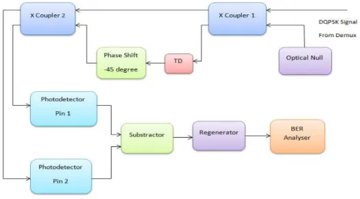
Fig. 1 (b) Block Diagram of DQPSK Receiver
The main aim of the present analysis is to explore the integration of DQPSK modulation in
UDWDM network. In this paper we have attempted to achieve long haul transmission with 32
DQPSK transmitters without using complex setup of polarization controllers, polarization splitters,
electronic signal processing and strict phase matching requirements and got appreciable results using
a much simpler setup.The DQPSK signals are decoded optically using a simple optical delay and add
interferometer structure as shown in Fig. 1(b). This design is basically based on direct detection
technique, avoiding the complex design of a DSP based coherent receiver.The MZI performs the
correlation of each received bit with that of its neighbor and performs the corresponding
phase-to-intensity conversion. To simultaneously receive the two transmitted data streams, the decoder needs
two Mach-Zehnder delay interferometers (MZDI) to match the phase difference of the I and Q branch
.This achieves the required delay in the two arms, thus realizing the coherency and cancellation of the
optical signals. The two balanced detectors similar to DPSK demodulators enable the upper and lower
branches to implement the required phase separation of π/4 and -π/4 [25]. The present design
compromises a little bit with the phase coherency requirement, but offers an acceptable insight of the
III. SYSTEM DESCRIPTION AND NUMERICAL MODEL
In DWDM environment, nonlinear propagation phenomena leads to either intra-channel effects,
which manifest themselves as non linear inter-symbol interference, or inter-channel effects, such as
XPM and FWM, and in a complex network scenario, these distortions are random and are customarily
treated as noise. The primary objective of analytical models of fiber propagation is to characterize this
noise accurately in terms of its statistical properties. Such models provide better insight by prediction
of nonlinear noise power and spectrum, estimation of system capacity considering the nonlinear noise
and, also the non-linear impact can be eliminated by selecting proper system parameters [26,27].
The major issues critical for the design of current and future WDM systems is the relationship
between transmitted signal modulation format, bit rate, optical channel spacing and parameters of
multiplexer and de-multiplexer filter [28]. Rigorous study and efficient modeling of non-linear effects,
has resulted in various approaches, each focusing on the features and requirements of the system
being analyzed. Investigation of the performance of DWDM systems incorporating the effect of fiber
nonlinearities uses primarily, numerical simulations, based on the solution of the nonlinear
Schrodinger equation (NLSE), as it allows visualizing the effect of each transmission impairment
individually, while making the computation of the collective effect of the simultaneous presence of various impairments also feasible. Propagation of signals in a two channel optical fiber system is governed by the following Coupled Nonlinear Schrodinger Equations [28].
� �� +
� �
�� + = � | | + | | … … … …
�
�� + �� − ����� +� ��� + = � | | + | | … …
Where A1 and A2 are complex amplitudes of electric field envelopes, 21 and 22 are GVD
dispersion parameters at channel 1 and β, respectively, α is fiber attenuation, is nonlinear coefficient
and dwalk − off is the walk–off parameter which accounts for group velocity mismatch between the
channels and can be approximately related to channel spacing ∆ and chromatic dispersion D as
follows:
�� − �� ≈ � ∆ … … …
where is the wavelength and c is the speed of light. Higher order dispersion is neglected in (1) and
(2) and XPM and SPM are the only included nonlinearities. The objective is to model the nonlinear
impact of intensity fluctuations of channel 1 on the phase of the signal in channel 2. A common
measure to avoid nonlinearities is to keep low launch powers to ensure linear propagation model.
However, it limits the maximum OSNR at the receiver and therefore the system performance.
leads to an optimal value refereed as NLT and it varies widely with fiber parameters and modulation
formats.
A multi-segmented, optically amplified UDWDM system is assumed as shown in Fig.2 to arrive at
the generalized forms of fiber non linearity-induced distortions. We consider chromatic dispersion as
a lumped distortion at the end of each span which is compensated by dispersion compensation (DC)
element, assuming no PM-IM conversion is involved. Only XPM and loss are considered to be distributed over the length of the fiber. The degree of XPM impairment is influenced by various
parameters, such as nonlinear fiber coefficient , walk-off between the two adjacent channels,
individual channel power and the modulation format used [29]. Phase modulated systems are very
sensitive to fiber non-linearities as the imposed phase shift directly affects the received signal. The
major source of intensity fluctuations is the ASE noise from optical amplifiers which results in nonlinear phase noise in long haul multi span systems. Signal launch power is kept low enough to
ensure that the system is not susceptible to SPM induced nonlinearities. Deployment of appropriate DCFs in the fiber link curtails the degradation due to Group Velocity Dispersion (GVD).
This model relies on the fact that a certain number of bits pass through the adjacent DQPSK
channel due to dispersion making the XPM induced phase shift to be bit pattern dependent. A
frequency difference of ∆ between the channels corresponds to ∆t, the time difference as � � ∆ / ,where D is the dispersion parameter, is the optical wavelength, L the fiber length, and c is the speed of light. The number of walk-of bits that pass from a particular point of the DQPSK signal over the
entire fiber length is defined as NW, and equals to ∆t B with B being the bit rate. This accounts for
determining the standard deviation of the DQPSK phase shift at the receiver side. In a fully dispersion
compensated system, both DCF and SMF have the same NW, but vary in the signal power level and
the direction of passing.
The nonlinear phase shift ∆ � is equal to β P∆z. For simpler calculations, it is assumed that power
level in DCF is too small to allow any considerable nonlinear phase shift and the major distortions occur in SMF. Moreover, we assume that the signal shape is not altered over the fiber length as major nonlinear crosstalk occurs in the initial fiber segment where the power is comparatively higher
[30,31].Considering ones and zeros to be equi-probable, a distribution of phase shifts corresponding
to a system with specific parameters is built and standard deviation of phase, � , is calculated as it is
shows the degree to which the phase modulated signal disperses and thus is a parameter for quality
assessment. The total phase shift is found by integrating the differential phase shifts along the fiber
length, as the power term depends both on the position and bit stream. The maximum possible phase
shift corresponds to the case when all NW bits are one and the minimum phase shift occurs when all
NW bits are zero, and phase shifts get distributed between these two limits. Thus, a bit stream of bi
∆∅� = ∑ �∆∅� ………. �
�=
where ∆∅� is the phase shift caused by ith bit given by:
∆∅� = [ �� − � � −�
� − �� (
��
��)] � � … … …
The BER is calculated from the standard deviation of the phase based on Eq. 6.
� = � �
√ � … … … … . .
In a multiple span system, any sample point on the DQPSK signal coincides with the same set of
bits, and experiences similar nonlinear phase shift in each span. Hence, we multiply � by the number
of spans to consider the effective phase shift for the entire system [32]. The BER in terms of Q-factor
for an optical link is given by :
= log ( ⁄ � − ) … … … . .
For error free communication, the threshold of optical communication system corresponds to a
BER of less than or equal to 10 −1β, translating to a Q-factor of greater than or equal to 6 or 15 dB as
obtained from Eq 7. This is considered as a reference and the performances for different cases is
evaluated based on Q-factor. The proposed 32 channels link constitutes of a transmitter section, fiber
module and an optical receiver as shown in Fig. 2 with the central frequency of the first channel as
193.1 THz.
The signal is launched with alternate polarization into the respective channels. The 40 Gbps
DQPSK signals with 50% duty cycle are generated by conventional transmitter setup shown in Fig
1(a). The input power is varied and the signal is launched over N spans of 60 Km each. The system
has been configured for both 25 GHz and 50 GHz channel spacing and a comparative assessment is
presented in terms of BER, Q-factor and eye opening. The emission frequencies of CW lasers are
equally spaced for both 25 and 50 GHz channel separation, and the optical channels have alternate
polarization. A 128-bit sequence with γβ samples per second modulates each channel. MZM’s with
the extinction ratio set to 30 dB are used. The modulated optical signal is fed to the 32 input ports of
an optical multiplexer. We optimized the type and order of both the multiplexer and the de-multiplexer filter as filter characteristics play a significant role in link design and evaluated the filter performance on the basis of receiver sensitivity in terms of the received Q value.
Crosstalk between the adjacent channels is avoided by tight optical filtering before multiplexing.
Each channel is filtered optically with a fourth order Bessel filter with a bandwidth of 25 GHz for 25
GHz channel separation and a bandwidth of 50 GHz for the other case. Optical filters for both
multiplexer and de-multiplexer are modelled by using the transfer function of ‘elevated cosine’
type with the center at the signal carrier frequency.
The combined optical signal is then fed into the SMF. Chromatic dispersion is compensated by
using a single-periodic amplification scheme at the span input (pre-compensation) Fig.2(a), at the
span output (post-compensation) Fig. 2(b) and along the span (inline-compensation) Fig.2(c) by
sections of DCF. It was observed that post compensation scheme provides an optimum performance
for DQPSK formats in agreement with the results in the literature [33] and hence this scheme has been
used in the present analysis. In each section, EDFA having a noise figure of 4 dB is used to
compensate the power loss of the link ignoring the corruption due to ASE noise.The fiber model in
OptiSytem takes into account the unidirectional signal flow, stimulated and spontaneous Raman
scattering, Kerr-nonlinearity and dispersion. An SMF with attenuation (α) of 0.ββ dB/km, dispersion
(D) of 17 ps/km-nm2 and dispersion slope (S) of 0.08 ps/nm2/km at 1550 nm, nonlinear refractive
index (n2) of 2.6×10−β0 m
2/W, and core effective area of the fiber (A
eff) as 80 m
2
has been
considered. The DCF segment used in each span has α of 0.5 dB/km, D of -85 ps/km-nm, S is -0.45
ps/nm2/km at 1550 nm, n2 = 2.6× 10−β0 m 2
/W and Aeff= γ0 m 2
.
The signal is first filtered by a γrd Order Bessel optical bandpass filter with a γ-dB bandwidth of 23
GHz for 25 GHz channel separation case, and a 2nd order Bessel optical bandpass filter with a γ-dB
bandwidth of 50 GHz for 50 GHz channel separation case, at the receiver side. This removes the ASE
noise power outside the signal bandwidth. Two asymmetrical Mach–Zehnder interferometer and two
balanced photodiodes detect this filtered optical signal, which now is filtered electrically by a fifth
-order Bessel filter with a γ-dB bandwidth of 40 GHz. The impact of FWM is weak compared to the
Self-Phase SPM and XPM due to the chromatic dispersion of the SMF [34] and is thus neglected.
results such as eye diagrams, BER, Q value, eye opening, etc.
IV. RESULTS AND DISCUSSIONS
First a 4 channel DQPSK modulated 25 GHz spaced system is designed and its performance is
evaluated at 0 dBm power level. We choose the DCF and SMF parameters to compensate the
first-order dispersion exactly (D=0) i.e. DSMFLSMF= DDCFLDCF, where D is the
first-order dispersion parameter [ps/nm/km] of the corresponding fiber and L stands for the total SMF or
DCF length per span. Then the number of channels was gradually increased to 8 ,16 and then to 32.
Table 1 presents a comparative assessment of Q factor observed vs. maximum distance traversed by
the optical signal for different channel spacing configurations. The dependency presented in the table
indicates an increase in the level of crosstalk with transmission by using a greater number of adjacent
channels. Though the starting Q value is nearly in the same range of all four cases, but the
transmission distance is around 1800 Km for 4 channels as compared to 900 Km for a 32 channel
case, clearly indicating the increase in XPM induced crosstalk.
Table 1: Q- factor for different number of channels No. Of Spans Q Factor
(4 channel) Q Factor (8 channel) Q Factor (16 channel) Q Factor (32 channel) 1 13.56 13.43 13.67 12.64 5 12.4 12.38 11.67 10.44 10 9.85 10.16 10.97 9.26 15 8.32 8.2 8.64 7.27 20 6.47 5.19 6.04 5.56 25 6.2 5.34 5.85 NA 30 6.51 NA NA NA 35 5.21 NA NA NA
Note: NA (Not acceptable as below 6 which is the reference value)
Fig 3.System performance comparision in the absence and presence of non-linearities.
0 5 10 15 20 25 30
0 300 600 900 1200 1500
Q F a ct o r (dB )
Distance (Km) for 0 dBm power
Gamma=2.09
For detailed analysis of UDWDM system, the influence of non-linearities is an important problem
to be investigated . So before implementation of a realistic 32 channel system ,the setup is first tested
for an ideal case with the fiber non-linear coefficient set to zero and the same is compared with a
practical case with a fiber having a typical as 2.09/w/Km working at 0 dBm power per channel. The
performance parameter has been evaluated for both the cases. The estimated Q value is better in the
absence of non-linearities as evident from the curves in Fig. 3. Since the main aim of the paper is to
study the effect of non linear impairments in a UDWDM system ,the further analysis is focused on
non linearities and its limitations.
The 32 channel system has been further analyzed for various input power levels. Fig.4(a)
-(c) outline the performance of both 50 GHz and 25 GHz spaced DQPSK system graphically in terms
of the Q value as a function of transmission distance. For a high data rate WDM system, it is
desirable that the input power should be as low as possible to limit non-linear effects hence we vary
the input power of each channel between - 5 dBm to 5 dBm .
Fig. 4(a) reveals that for very low power levels of -5 dBm, the 25 GHz DQPSK modulated system
manages to run for 10 spans i.e. a distance of 600 km, while the 50 GHz system attains a transmission
distance 900 km. The initial Q value after the first span is 20 dB for 50 GHz case, while it is 18 dB for
25 GHz .The curves overlap between 500 to 700 Km indicating similar performance in both the cases.
As the power increases to -1 dB, the safe operating distance increases in both cases, being close to
1200 km for 50 GHz case and around 1000 km for the latter. Another point to be noted is that tough
the Q value for 25 GHz separation remains below the former, but the initial Q values also increase
close to 24 dB as compared to 18 dB for -5 dBm power level.
Performance at 0 dBm power follows closely the case of -1 dBm as highlighted in Fig.4 (b) for both
cases. We achieve a safe operating distance of 1500 Km for 50 GHz case and upto 1200 km for 25
GHz spacing, before the Q-value degrades below 15 dB threshold. So, we can infer that the DQPSK
modulation format is more suitable for higher values of power as it offers generous system margin
due to its high spectral efficiency and relatively good tolerance to fiber degradations making it
desirable for long haul transmission.
At 1 dBm launch power initially the Q value increases up to 26 dB and it performs well for
distances over 1200 Km, but the curves do not follow each other closely. For the 5 dBm launch power
case as in Fig.4 (c), 50 GHz system outperforms the 25 GHz one from the first span with as starting Q
value close to 30 dB as compared to 26 dB for 25 GHz case and maintains its superiority up to 1100
Km, while the 25 GHz system falls below the threshold at 1000 Km only. In both the cases, a
Fig.4(a)
Fig.4(b)
Fig.4(c)
The performance of 50 GHz system no doubt is better as compared to 25 GHz case, but even for the
latter the Q value maintains above the FEC threshold for upto 1000 km which is an interesting
observation. In work [37] experimental and numerical investigations of the transmission reach of
PS-QPSK and PM-PS-QPSK are reported for three different fiber span lengths i.e. 83, 111 and 136 km which
is lesser as compared to the present investigation and moreover it operates with only 9 channels on a
50 GHz grid. In work [38] the performance of 42.8-Gb/s and 112-Gb/s intradyne coherent PM-QPSK
system is studied with inline DCF to acheive a distance reach of 1000-km which is comparable to our
results but with a higher cost and complex design. Our findings reinstates that using DQPSK over
UDWDM offers two key functionalities: (i) better wavelength selectivity removes the requirement of
expensive ultra-dense filter technology; (ii) high receiver sensitivity enables a system with longer
reach.
V. CONCLUSION
The paper successfully demonstrates the transmission of 32 DQPSK modulated channels up to
1500 km in the presence of various simulated fiber nonlinearities. The OptiSystem trans-receiver
model is developed to estimate the comparative transmission performance parameters of the proposed
UWDM systems operating at 25 GHz and 50 GHz channel spacing at various input power levels. The
simulation study of the results shows that DQPSK modulation is better in terms of crosstalk
mitigation during the transmission of signals. It also outperforms at higher launch powers due to its
better spectral efficiency, enabling it to tolerate the dispersion induced degradations. The observations
of the present analysis are useful for an experimentalist to visualize the various complexities involved
in such high speed links. However, the scope still remains open to choose the preferable fiber to
transmit DQPSK modulated signals with varying duty cycle. As very few UDWDM system
experiments have been conducted till now, so the fundamental limiting factors and their remedies in
such systems are not clearly defined, especially when transmitting at a data rate higher than 40 Gb/s.
Thus, it is inferred that at these data rates severe chromatic dispersion and polarization-mode
dispersion limitations need to be addressed before dealing with optical non linearity-induced
penalties. Integration of coherent technology based on PM-QPSK, PS-QPSK, PM-16 QAM and
DP-QPSK with UDWDM also needs to be explored as a part of future work as usage of DSP relaxes the
equalization of transmission impairments as well as implementation of forward error correction.
Acknowledgement
Authors are thankful to the Director, B.I.T.S-Pilani for extending the facility in the optical
REFERENCES
[1] G. P. Agrawal, Fiber-Optic Communication Systems, third ed., Wiley, NewYork, 2002.
[2] P.J. Winzer, R.J. Essiambre, Advanced Optical Modulation Formats, Proceedings of the IEEE, Vol. 94, No.5, (2006) 952–985.
[3] G.P. Agrawal, Nonlinear Fiber Optics, fourth ed., Academic Press, New York, 2001.
[4] G. Charlet, Progress in Optical Modulation Formats for High-Bit Rate WDM Transmissions, IEEE Journal Of Selected Topics In Quantum Electronics, Vol. 12, No. 4, (2006) 469–48.
[5] L.N Binh, Digital Optical Communications ,first indian edition ,CRC press, 2012.
[6] M. Birks, B. Mikkelson, 40 Gbit/s upgrades on existing 10 Gbit/s transport infrastructure, Proceedings of SPIE, Vol. 6012, (2005) 60120D.
[7] T. Hoshida, O. Vassilieva, K. Yamada, S. Choudhary, R.Pecqueur, H. Kuwahara, Optimal 40 Gb/s modulation formats
for spectrally efficient long-haul DWDM systems, IEEE Journal of Lightwave Technology,Vol. 20, No.12,(2002) 1989-1996.
[8] A. Hodzik, B. Konrad, K. Petemann, Alternative modulation formats in N X 40 Gb/s WDM standard fiber RZ -transmission systems, IEEE Journal of Lightwave Technology, Vol. 20, No.4, (2002) 598-607.
[9] L. Sharan, V K Chaubey, Design and Simulation of CSRZ Modulated 40 Gbps DWDM System in Presence of Kerr Non Linearity, IEEE Xplore, 9th International Conference on Wireless and Optical Communications, Indore (2012) 1-5.
[10] O.V. Shtyrina, M.P. Fedoruk, S.K. Turitsyn, Study of new modulation data-transmission formats for dispersion-controlled high-bit-rate fiber optic communication lines, Journal of Quantum Electronics (IOP Science), Vol.37, No. 9, (2007) 885 - 890.
[11] L. Sharan, V K Chaubey, Design and Simulation of Long-Haul 32 x 40 Gb/s Duobinary DWDM Link in the Presence of Non-Linearity with Under-compensated Dispersion, IEEE Xplore, 3rd International Conference on Photonics, Malaysia, (2012) 210-214.
[12] A. Sheetal, A. K. Sharma, R.S. Kaler, Simulation of high capacity 40Gb/s long haul DWDM system using different modulation formats and dispersion compensation schemes in the presence of Kerr's effect, Optik (Elsevier), Vol.121, (2010) 739-749.
[13] V. Tavassoli, T.E. Darcie, An analytical method for performance evaluation of a DQPSK channel in presence of OOK signal, Proceedings of the SPIE ,Vol.7386, Photonics North (2009) 73861C .
[14] B. Linlin, L. Jianming, L. Li, Z. Xuecheng, Comprehensive Assessment of New Modulation Techniques in 40Gb/s Optical Communication Systems, IOP Publishing, 3rd International Photonics & OptoElectronics Meetings, Journal of Physics:Conference Series 276 (2011) 012054.
[15] A. Tan, E. Pincemin, Performance comparison of duobinary and DQPSK modulation formats for mixed 10/40-Gbit/s
WDM transmission on SMF and LEAF fibers, Journal Of Lightwave Technology, Vol. β7, No. 4, (β00λ) γλ6-408.
[16] P. Zhang, L. Liren, J. Huilin, K. Xizheng, F. De-jun, W. Huang, D. Jia, J. Ma, Comparison of dispersion compensation for DQPSK modulated formats in 100 Gbps DWDM optical communication system, Proceedings of the SPIE ,Vol.8906, International Symposium on Photoelectronic Detection and Imaging , Laser Communication Technologies and Systems, (2013) 89061E.
[18] M. Wu, W.Y Way, Fiber Nonlinearity Limitations in Ultra-Dense WDM Systems, Journal of Lightwave Technology, Vol.22, No.6 (2004) 1483-1498.
[19] V.Tavassoli, High Capacity Phase/Amplitude Modulated Optical Communication Systems and Nonlinear Inter-Channel Impairments , Phd Thesis , University of Victoria, 2012.
[20] J D. Reis, D M. Neves, A. L. Teixeira, Analysis of Nonlinearities on Coherent Ultradense WDM-PONs Using Volterra Series, Journal of Lightwave Technology, Vol. 30, (2012) 234-241.
[21] M. Jaworski, Performance Evaluation of Multilevel Optical Modulation Formats , IEEE Xplore, 7th International Conference on Transparent Optical Networks, Spain, (2005) 389-392.
[22] V. Tiwari, D Sikdar, M. N. Jyothi, G. Dixit, V.K Chaubey, Investigation of optimum pulse shape for 112 Gbps DP-DQPSK in DWDM transmission, Optik (Elsevier), Vol. 124, (2013) 5567-5572.
[23] J. Wang, K. Petermann, Small Signal Analysis for Dispersive Optical Fiber Communication Systems, Journal of Lightwave Technology, Vol 10, (1992) 99-100.
[24] D. Wangc, J. Zhang, G. Gao, X. Cheng, S. Chen, Y. Zhao, W. Gu, Pulse broadening factor as a criterion to assess nonlinear penalty of 40-Gbit/s RZ-DQPSK signals in dynamic transparent optical networks, Optical Fiber Technology,Vol.17, ( 2011), 305–309.
[25] V. Tiwari, D Sikdar, V.K Chaubey, Performance optimization of the RZ-DQPSK modulation scheme for dispersion compensated optical link, Optik (Elsevier), Vol. 124, ( 2013) 2593-2596.
[26] L. Lia, J. Zhang, D. Duana, A. Yin, Analysis modulation formats of DQPSK in WDM-PON system, Optik (Elsevier), Vol. 123, (2013) 2050-2055.
[27] OptiSystem Application Notes and Examples(2010), Optiwave, Ottawa, ON, Canada.
[28] T. Tokle, C.R. Davidson, M. Nissov, J.X. Cai, D. Foursa, A. Pilipetski, 6500 km transmission of RZ-DQPSK WDM signals, IEEE Electronics Letters, Vol. 40 , No. 7, (2004) 444 - 445.
[29] S. Chandrasekhar, X. Liu, Impact of Channel Plan and Dispersion Map on Hybrid DWDM Transmission of 42.7 Gb/s DQPSK and 10.7 Gb/s OOK on 50-GHz Grid, IEEE Photonics Technology Letters, Vol. 19, No. 22, (2007) 1801–1803.
[30] C. R Silveira, D.M. Pataca, M.A. Romero, M .L Rocha, A Cost-Benefit Analysis on Modulation Formats for 40-Gb/s Optical Communication Systems, Fiber and Integrated Optics,Vol. 30, No. 2 (2011) 87-101.
[31] B. Patnaik, P.K. Sahu, Ultra high capacity 1.28 Tbps DWDM system design and simulation using optimized modulation format, Optik (Elsevier),Vol.124, No. 14 (2013)1567-1573.
[32] S.L. Jansen, D.Borne, P.M. Krummrich, G.D Khoe , H. Waardt, Experimental Comparison of Optical Phase Conjugation and DCF Aided DWDM 2 x 10.7 Gbps DQPSK Transmission, Proceedings of the 31st European Conference on Optical Communication, Scotland, Vol. 4, (2005) Th 2.2.3.
[33] G. Goeger, M. Wrage, W. Fischler, Cross-Phase Modulation in Multispan WDM systems with Arbitrary Modulation Formats, IEEE Photonics Technology Letters, Vol 16, No.8, (2004) 1858-1860.
[34] M. Shtaif, "Impact of cross phase modulation in WDM systems," in Proceedings of the Optical Fiber Communication Conference, Baltimore, (2000), Paper ThM1 (invited).
[35] N Eduardo S. Rosa,Victor E. S. Parahyba, Júlio C. M. Diniz, Vitor B. Ribeiro , Júlio C. R. F. Oliveira,Nonlinear Effects Compensation in Optical Coherent PDM-QPSK Systems,Vol. 12, No. 2, (2013) 707-717
[36] Li L, C Jin-ling,d Zhang Ji-jun, Research of 100 Gbit/s DP-QPSK Based on DSP in WDM-PON System, International Journal of Signal Processing, Image Processing and Pattern Recognition, Vol.8, No.3 (2015),121-130.
[38] J. Zheng, F. Lu, M. Xu, M. Zhu, Md I. Khalil, X. Bao, D. Guidotti, J. Liu, N. Zhu, Gee-Kung Chang, A dual-polarization coherent communication system with simplified optical receiver for UDWDM-PON architecture,Optics Express Vol. 22, No. 26, (2014) 31735.
[39] C. Xie ,WDM coherent PDM-QPSK systems with and without inline optical dispersion compensation, Optics Express,Vol. 17, No. 6 ,(2009) 4815.