Chemical resistance of lime-based grouts
for masonry strengthening
Manuk Aghajanyan
Final dissertation report submitted to
Escola Superior de Tecnologia e Gestão
Instituto Politécnico de Bragança
To obtain the Master Degree in
Chemical Engineering
Chemical resistance of lime-based grouts
for masonry strengthening
Manuk Aghajanyan
Final dissertation report submitted to
Escola Superior de Tecnologia e Gestão
Instituto Politécnico de Bragança
To obtain the Master Degree in
Chemical Engineering
Supervisors
Professor Ana Maria Alves Queiroz Silva
Professor Eduarda Cristina Pires Luso
Professor Marine Petrosyan
iii
Acknowledgements
I would like to take this opportunity to first and foremost thank God for being my strength and guide in the writing of this thesis. Without Him, I would not have had the wisdom or the physical ability to do so.
I would like to express my gradtitude to my supervisers Prof. Ana Maria Alves Queiroz Silva, Prof. Eduarda Cristina Pires Luso and Prof. Marine Petrosyan for their tremendous support and guidance throughout my research.
I would like to acknowledge the academic and technical support of Escola Superior de Tecnologia e Gestão Instituto Politécnico de Bragança and all professors and staff of the departments of chemical engineering and civil engineering.
iv
Abstract
The stone masonry walls are present in many buildings and historical monuments, with undeniable asset value, but also in old buildings housing both in Portugal and in Europe. Most of these buildings in masonry are in certain cases in a high state of degradation needing urgent intervention. This requires the identification of deficiencies and the application of appropriate intervention techniques. One of the possible techniques for structural consolidation works of stone masonry walls is the injection of fluid mortars currently called grouts. The choice of grouts is very important with regard in particular to their chemical and physical properties. In this study, carried out under the Master of Chemical Engineering, two types of lime-based grouts were used, in order to evaluate and compare their chemical resistance due to the crystallization of soluble salts. One of the grouts is a pre-dosed blend commercially available, Mape-Antique I from company Mapei (CA), and the second grout is a mixture prepared in the laboratory (LB), comprising metakaolin, cement, hydrated lime, water and superplasticizer. With the purpose of evaluating the action of sulphates on these grouts, a series of samples underwent several wetting-drying cycles using two different temperatures, 20 °C and 50 °C. During the experiment it was determined the change of weight and compressive strength in the analyzed grouts, as well as the sulphate ion concentration and pH of the solution in which the samples were dipped. The commercial grout (CA) apparently has a greater chemical resistance to sulphates. However grout LB showed to have positive results in some parameters.
v
Resumo
As paredes de alvenaria de pedra estão presentes em muitos edifícios e monumentos históricos, com valor patrimonial inegável, mas também em edifícios antigos de habitação de construção antigos, tanto em Portugal como na Europa. Grande parte destas edificações em alvenaria encontra-se, em certos casos, num elevado estado de degradação pelo que necessitam de intervenção urgente. Isto requer a identificação das deficiências e a aplicação de técnicas de intervenção apropriadas. Uma das técnicas possíveis para trabalhos de consolidação estrutural das paredes de alvenaria de pedra é a injeção de argamassas fluidas denominadas correntemente por caldas. A escolha destas caldas é muito importante no que respeita, em particular, às suas propriedades químicas e físicas. Neste estudo, realizado no âmbito do Mestrado em Engenharia Química, foram utilizados dois tipos de caldas à base de cal, com a finalidade de comparar e avaliar a sua resistência química face à cristalização de sais solúveis. Uma das caldas é uma mistura pré-doseada comercialmente disponível, a Mape-Antique I da empresa Mapei (CA) e a segunda calda é uma mistura preparada em laboratório (LB), composta por metacaulino, cimento, cal hidratada, água e um superplastificante. Com o proposto de avaliar a ação dos sulfatos sobre estas caldas, submeteram-se uma série de provetes a ciclos molhagem-secagem usando duas temperaturas diferentes, 20 °C e 50 °C. Durante a experiência determinou-se a
variação do peso e da resistência à compressão das caldas analisadas, assim como a concentração de ião sulfato e pH da solução onde foram mergulhadas as amostras. A calda comercial (CA) apresenta aparentemente uma resistência química aos sulfatos superior, no entanto a calda LB mostrou ter, em alguns parâmetros, resultados positivos.
vi
Ամփոփում
Ժամանակի ընթացում ցեմենտաքարային կառույցների վրա, արտաքին միջավայրի ազդեցությունից առաջացած վնասվածքները վերականգնելու համար օգտագործվում են ցեմենտային խառնուրդներ: Ցեմենտային
խառնուրդների համար մեծ կարևորություն ունեն թե քիմիական, և թե
ֆիզիկական հատկությունները: Քիմիական կայունությունը համեմատելու և
գնահատելու համար ընտրվեցին երկու տեսակի ցեմենտային խառնուրդներ,
նրանցից մեկը շուկայում առկա Mapei, Mape Antique I է, իսկ մյուսը`
լաբորատորական հետազոտությունների արդյունքում ստացված խառնուրդը:
Փորձի ընթացքում օգտագործվեցիրար հաջորդող խոնավացման և չորացման
ցիկլային մեթոդը: Նմուշների խոնավացման համար ընտրվեց նատրիումի
սուլֆատի 5 տոկոսանոց լուծույթ, իսկ չորացման համար մինչև 6-րդ ցիկլը
իրականացվեց 20 °C-ում, այնուհետև 6-րդ ցիկլից սկսած նմուշների կեսը
չորացվեցին 20 °C ջերմաստիճանում, իսկ մյուս կեսը 50 °C-ում: Փորձի
ընթացում հետազոտվեցին նմուշների զանգվածները և սեղմման ամրության
սահմանը, իսկ նատրիումի սուլֆատային լուծույթի՝ որը օգտագործվել էր
նմուշների խոնավեցման համար, սուլֆատի քանակի և ջրածնային ցուցիչի
(pH) փոփոխությունները: Ստացված արդյունքներից հետևում է, որ
լաբորատորիայում ստացված ցեմենտային խառնուրդը քիմիապես կայուն չէր
ի շնորհիվ ջուր և կապակցող նյութ արժեքի բարձր հարաբերակցության և
նրանում առկա ալյումինի օքսիդիբարձր չափաբաժնով:
Առանցքային բառեր: Կրային խառնուրդներ, քիմիական կայունություն,
vii
Index of figures
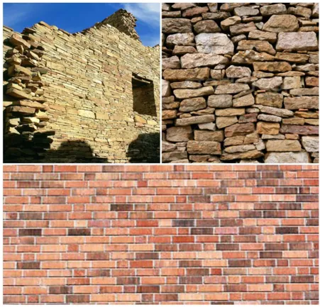
Figure 1-Masonry walls constructed with stones and bricks ... 5
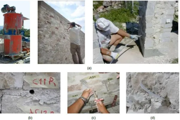
Figure 2-Grout injection procedure. (a) General overview of the process. (b) Drilling holes in mortar joints. (c) Fixing plastic pipes. (d) Injecting grout ... .6
Figure 3-Hand and gravity grouting [5] ... 7
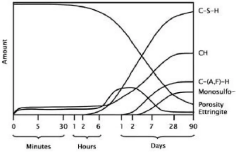
Figure 4-Schematic view of cement hydrates formation ... 9
Figure 5-Lime Cycle ... 12
Figure 6-Relationship between permeability and porosity ... 20
Figure 7-Salt attack in bricks causing damage ... 21
Figure 8-Effect of temperature on sulphate-bearing phases stability [8] ... 23
Figure 9-Ettringite stability in alkaline environments as a function of pH and sulphate ion concentration [33] ... 24
Figure 10-The sodium sulphate phase diagram [36] ... 25
Figure 11-Filled blend of commercial grout in the moulds ... 28
Figure 12-Available specimens of grout CA ... 28
Figure 13-Filled blend of LB in the moulds ... 29
Figure 14-pH meter ... 34
Figure 15-Stirring machine... 35
Figure 16–Spectrophotometer ... 35
Figure 17–Balance ... 36
Figure 18-Oven Binder FP115 ... 37
Figure 19-Oven Binder FP720 ... 37
Figure 20-Humidity chamber ... 37
Figure 21–Compressive testing machine. ... 38
Figure 22- Testing of specimen ... 38
Figure 23-Digital balance ... 39
Figure 24-Digital calliper ... 39
viii
Figure 27- Compressive test results of commercial specimens ... 44
Figure 28-Compressive test results of lab-specimens ... 44
Figure 29-pH of commercial specimens solution ... 46
Figure 30-pH of lab specimens solution ... 47
Figure 31-Calibration curve of sulphates using turbidimetric method... 48
Figure 32-Sulphate concentration changes in solution of commercial specimens during the time ... 49
Figure 33-Sulphate concentration changes in solution of lab-specimens during the time ... 49
Figure 34-Weight changes of commercial specimen at 20 °C and 50 °C ... 50
Figure 35-Weight changes of lab-specimen at 20 °C and 50 °C ... 50
Figure 36-Evolution and damages of commercial specimens CA (left) and lab-specimens LB (right) subjected wetting-drying cycles ... 52
ix
Index of tables
Table 1-Types of Cement, within European standard EN 197-1[8] ... 10
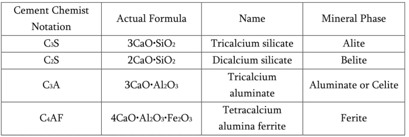
Table 2-Clinker main minerals (phase composition of cement clinker) ... 11
Table 3-Types of building lime and classification ... 13
Table 4-The classes of calcium lime and dolomitic lime ... 13
Table 5-Types and classification of hydraulic lime ... 14
Table 6-Classes of hydraulic lime within EN 459-1:2001 ... 14
Table 7-Chemical composition of metakaolin (HRM) ... 15
Table 8-Types of additives water reducing/ high water reducing ... 17
Table 9-Information available in the technical data sheet from the producers ... 19
Table 10–Salt types ... 21
Table 11-Initial information (weight, volume and bulk density and) of the commercial specimens (CA) ... 30
Table 12-Initial information (weight, volume and bulk density) of the lab-specimens (LB) ... 31
Table 13-Initial information (compressive strength and coefficient of variation) of commercial samples ... 32
Table 14-Initial information (compressive strength and coefficient of variation) of the lab-samples ... 32
Table 15-Specifications of sodium sulphate hydroxide and decahydrate, barium chloride dihydrate, sodium acetate trihydrate, magnesium chloride 6-hydrate, potassium nitrate and acetic acid ... 33
Table 16–Technical specifications of used pH meter ... 34
Table 17-Specifications of used stirring machine ... 35
Table 18-Specicfications of the spectrophotometer ... 36
Table 19-Specifications of the balance for weighting reagents ... 36
Table 20-Specifications of the ovens ... 37
Table 21-Specifications of the chamber humidity ... 38
x
Table 23-Used specimen numbers at each cycle ... 41
Table 24-Compressive test results of commercial specimens ... 45
Table 25-Compressive test results of lab-specimens ... 46
Table 26-Daily weight changes of specimens ... 61
Table 27-Bulk density of commercial specimens ... 62
xi
Contents
Chapter 1 – Introduction ... 1
1.1. Motivations of the thesis ... 2
1.2. Objectives of the thesis ... 2
1.3. Synopsis of the thesis... 3
Chapter 2 - State-of-the-Art ... 4
2.1. Grouting as a repair and conservation method of ancient masonry structures .. 4
2.2. Materials constituents of grouts ... 8
2.2.1 Introduction ... 8
2.2.2. Cement ... 8
2.2.3. Hydrated Lime ... 12
2.2.4. Hydraulic Lime ... 13
2.2.5. Metakaolin ... 14
2.2.6. Superplasticizers and Plasticizers ... 16
2.3. Commercially available grouts and laboratory Formulations – Literature Survey... 18
2.4 Durability of Construction Materials – Chemical Resistance ... 19
2.4.1. Evaluation of Sulphate attack Resistance – Literature Survey ... 21
2.4.2. Evaluation of chloride attack Resistance – Literature Survey ... 26
Chapter 3 – Experimental Program ... 28
3.1. Materials and Preparation of Specimens ... 29
3.2 Reagents ... 32
3.3. Equipments ... 33
3.4. Preparation of sulphate solution... 39
3.5. Wetting and Drying Cycles ... 40
3.6. Measurement of Compressive Strength ... 40
3.7. Measurement of pH ... 41
3.8. Measurement of sulphate concentration... 42
xii
Chapter 4 – Results and Discussion ... 44
4.1. Compressive Strength ... 44
4.2. pH ... 46
4.3. Sulphate concentration ... 48
4.4. Weight ... 50
4.5.Damage ... 51
Chapter 5 - Conclusions ... 54
5.1. Conclusions ... 54
5.2. Limitation and Future works ... 55
References ... 56
xiii
Nomenclature
A-Surface area (cm2)
Abs-Absorbance
AFm- Alumina, ferric oxide, mono-sulphate
CA–Commercially available grout
C3A- Tricalcium aluminate
C4AF- Tetracalcium alumina ferrite
CH-Calcium Hydroxide CL- Calcium Lime Conc-Concentration
C-S-H-Calcium Silicate Hydrate C3S- Tricalcium aluminate
C2S- Dicalcium silicate
CV- Coefficient of variation DL- Dolomitic Lime
F- Applied force (kN) H-Height (mm)
H+- Hydrogen ion concentration
HL- Hydraulic Lime
HRM- High reactivity metakaolin L-Length (mm)
LB- Laboratory formulation grout
LOI-Loss on ignition M -Weight (g)
Max-Maximum MK-Metakaolin
NH- sodium hydroxide
xiv
s-Standard deviation
SCMs- Supplementary cementitious materials SP-Superplasticizer
T-Specimen is tested V -Volume (cm3)
W-Width (mm) W/B-Water-binder W/C-Water-cement ratio
f - Compressive strength (repeat)
ρ -Bulk density (g/cm3)
X -Mean
1
1.
Chapter 1 - Introduction
Because of environmental conditions a lot of mechanical and chemical processes befall on buildings during years. To repair ancient masonry structures, the method of grouting is being used. Different techniques for repair and strengthening of stone masonry and brick walls were used in the seventies in Italy after earthquakes. Nowadays, one of the most famous technique is the injection grouting. For grouting it is important to choose durable grout. Based on these attributes the chemical resistance of lime-based grouts may also be affected due to environment factors (including rainwater, temperature, humidity). Within this study two types of grout have been chosen to evaluate their resistance to sulphates (Na2SO4) attack and then they are
compared to choose the most suitable repair grout. Sodium sulphate is generally regarded as one of the most destructive salts in the weathering of historical objects. In this case water soluble salts can be accumulated in porous buildings materials and cause degradation connected with salt crystallization. The crystallization can either be induced by drying and/or cooling of a salt solution in a porous material [1]. In order to determine the chemical strength of both grouts the wetting-drying weathering process was used. A total of forty-two grout specimens were prepared and all the samples were initially dried to constant mass at 105 °C for 18 hours. The initial weight, dimensions and surface appearance of the specimens were recorded and a compressive test was done. Changes in weights of the specimens were measured every day during the experiment. Because of the two types of grouts, sodium sulphate solution was prepared and it was filled into two different containers. PH and sulphate concentration of both solutions were also measured every day until the 12th cycle, then after started 12th cycle
each tree days taking 20 mL from both solutions (CA, LB), totally 40 samples (19 from grout CA and 21 from grout LB). After 13th, 20th, 36th wet/dry cycles, the specimens
2
during the remaining 30 days without controlling the pH. It should be noted that it is very important to do everything in time without missing cycles and to make sure that specimens are completely immersed in the sulphate solution.
1.1. Motivations of the thesis
It is known that during ageing process of masonry structure damages occur on it. This phenomenon has been observed on historic as well as on modern buildings. The most important factors influencing degradation and damage to masonry are related to environment, used materials, design of building and its maintenance. To solve this problem, the repairing method is being used. It is possible to repair by using injection technique and grout. The main problem concerning the reparation of buildings with grout is the choice of grout materials which should be compatible with original materials. Grouting is a well-known technique, which allows to preserve rheological, physical, chemical and mechanical properties. All these things and plus the wish to work with cementitious substances were the primary reasons to start this subject and compare two types of grouts in order to decide which one of them is the more chemically resistance.
1.2. Objectives of the thesis
3
one is a laboratory formulation containing 35% of hydrated lime, 30% of cement and 35% of metakaolin mixed with a plasticizer. The objective is to compare these two grouts using wetting-drying method and to understand which one has the best chemical resistance.
1.3. Synopsis of the thesis
In order to answer the defined objectives, the thesis is organised in five chapters. In the first chapter, Chapter 1 – introduction, the motivation behind the study and the objectives of this study are briefly presented.
In the second chapter, the materials used in the study as well as a bibliographic review related to this study is presented.
In the third chapter, the research strategy materials, methodology and analysis parameters adopted are described.
4
2.
Chapter 2 - State-of-the-Art
2.1. Grouting as a repair and conservation method of ancient masonry structures Masonry structures are famous since ancient centuries. Masonry walls are composite structures defined as macroscopic combinations of two or more distinct materials having a finite interface between them. Formerly in masonry walls basically were used stones, granites etc. with or without lime based bonding mortars. Nowadays, the more common materials are bricks, blocks and cementitious binders as bonding mortars (Figure 1). During years it befalls lot of mechanical and chemical processes on buildings. To repair of ancient masonry structures, the method of grouting is being used. There are different techniques for the repair and strengthening of stone masonry and brick walls. These techniques have been used yet in the seventies in Italy after quakes. Grouting is a technique which is being used to fill voids and re-establish the continuity of the constructional components of a disintegrated masonry. The main problem of the technique depends on small sizes of voids in masonry or the shortage of communication in case of diffused cracks and the difficulty of the grout to penetrate into thin cracks. The repair and strengthening with grouting gives the best result because it does not change morphology and load bearing system. These are the objectives of grouting technique [2].
Reconstitute the structural continuity of the masonry; Increase the masonry homogeneity, filling voids, if existing;
Improve the masonry mechanical properties, (increase the masonry strength);
5
Figure 1-Masonry walls constructed with stones and bricks.
6
final performance characteristics. Both the stirring method and the time of mixing have an essential influence on the stability of the grout mixture. Generally, mixing an injection grout at high speed for a longer time produces a grout with better injectability and penetration and less separation of liquid and solid phases [4].
Figure 2-Grout injection procedure. (a) General overview of the process. (b) Drilling holes in mortar
joints. (c) Fixing plastic pipes. (d) Injecting grout
Injection grouting (Figure 3) for the conservation of stone masonry structures involves several steps described below [2]:
Study and choice of the grout;
Selection of the injection points, the distance between injectors and their layout, according to the crack diffusion, depth, with and localisation;
Removal of the damaged plaster and superficial crack filling (to avoid loss of grouts);
Positioning of the injection injectors and repointing by mortar;
7
Evaluation of the injection pressure; Grout injection.
In literature there are four general methods for grouting, whose choice depends on nature and condition of masonry. The methods are [5]
Hand grouting Gravity grouting Pumped system Vacuum system
The simplest method is the hand grouting. This technique is being used for small isolated voids or fine cracks. Gravity grouting is suitable for ancient masonry structures and for filling large voids and it is also necessary to mention that during this method the pressure in the hose should be 70-80kPa (Figure 3). Pumped system is recommended for ancient masonry in unstable conditions. Here the pressure ranges from 70-280kPa and this method is used in large-scale grouting (tunnels, vaults). The vacuum system for masonry structures, indicative to say that at present time information of this system very limited [5].
8
2.2. Materials constituents of grouts 2.2.1. Introduction
Injection grouts are composed of one or more binders, aggregates or not, admixtures (typically superplasticizers or plasticizers) and water. To obtain similar and good injectability the use of superplasticizer for some grouts is essential.
The binders are divided into inorganic (aerial or hydraulic binders) and organic binders. Hydraulic binders include cement and hydraulic lime. Whereas, aerial binders include the gypsum and hydrated lime. The combination of different materials gives totally different results with different properties and behaviour, namely injectability, mechanical and durability characteristics. As it is known there are basic types of grout, which are non-sanded (or unsanded) and sanded.
In this study non-sanded grout is used. To prepare specimens cement, hydrated lime, metakaolin and superplastizier were used in this study. These materials are explained below.
2.2.2. Cement
9
into account when determining the stability of cement. This is represented in (Eq. 2) [6]
Tricalcium Silicate + Water→ Calcium Silicate Hydrate+ Calcium Hydroxide
2 (CaO)3(SiO2) + 7H2O → (CaO)3•(SiO2)2•4(H2O) + 3Ca(OH)2 (Eq. 1)
Dicalcium Silicate + Water → Calcium Silicate Hydrate + Calcium Hydroxide
2(CaO)2(SiO2) + 5H2O → (CaO)3•(SiO2)2•4(H2O) + Ca(OH)2 (Eq. 2)
The other major components of Portland cement, tricalcium aluminate and tetracalcium alumina ferrite also react with water. Their hydration chemistry is more complicated as it involves reactions with the gypsum as well. Because these reactions do not contribute significantly to strength they are not written in the frame of this study. After mixing the acquisition paste it is possible to use within three hours, but it depends on the composition and fineness of the cement, usage of any admixtures, mixture proportions, and temperature conditions. Most of the hydration and strength development takes up to the first month, however, it continues for a long time with proper moisture and temperature. Continuous strength increases exceeding 30 years have been recorded [7] see Figure 4.
Figure 4-Schematic view of cement hydrates formation.
10
found by EN 197-1 European standard and the I II, III IV, V are types of cement. In this time the most famous type of cement is Portland cement. Portland cement is made by heating a mixture of limestone and clay in a kiln at about 1450°C, then grinding up to a fine powder with a small addition of gypsumto control flash setting. Initial setting and early strength of Portland cement is due to tricalcium aluminate (C3A). Tricalcium
silicate is a very reactive compound, hydrates quickly and contributes more to the early strength. Basically the early high strength related with increased percentages of C3S.
The contribution of dicalcium silicate (C2S) takes place after 7 days and may continue
for up to 1 year, because it enters slowly to reaction then tricalcium silicate. Tricalcium aluminate hydrates quickly, generates much heat and makes only a small contribution to the strength within the first 24 hours and it has problems with sulphate attack. As is known for obtaining sulphate resistant cement is necessary to reduce C3A content in
clinker because sulphate reacts with aluminate and calcium components to produce disruptive products such as ettringite and gypsum.
11
As this has been studied at the U.S. Bureau of Reclamation in the 1960s and 1970s they pointed out that higher amount of the highly reactive alumina is less suitable than small amount for improving the sulphate resistance of concrete which means that with increased Al2O3 content can be more susceptive to the formation of ettringite [9].
Gypsum, which is added to cement during final grinding, slows down the initial hydration rate of C3A. Cements with low percentages of C3A are especially resistant to
soils and waters containing sulphates. Tetracalcium alumino-ferrite is comparatively inactive. It hydrates relatively slowly and contributes very little to strength. C4AF and
its hydrates influence on colour [10] [11].Often supplementary cementitious materials (SCMs) are blended with clinker, including fly ash, ground granulated blast furnace slag, silica fume, calcined clays and natural pozzolans. The practice of using SCMs is increasing, with the world average percent clinker in cement having decreased from 85% in 2003 to 77% in 2010, and it is projected to further decrease to 71% in the future [12]. Basically Portland cement is familiar by grey colour but there is also a white Portland cement and sulphate resisting Portland cement. Clinker consists of various calcium silicates including alite, belite celite and ferrite. The raw materials (clay and limestone) for clinker manufacture consist primarily of materials that supply four primary oxides. Typical clinker contains 67 % СаО, 22 % SiO2, 5 % Al2О3, 3 %
Fe2O3 and 3 % other components with % w/w and usually four major crystalline phases
[13] which are shown in Table 2. Depending on the percentage of clinker and gypsum (calcium sulphates) and possibly additional cementitious (slag, fly ash, natural pozzolanas, etc.) in cement different types of cement are generated.
Table 2-Clinker main minerals (phase composition of cement clinker).
Cement Chemist
Notation Actual Formula Name Mineral Phase
C3S 3CaO•SiO2 Tricalcium silicate Alite
C2S 2CaO•SiO2 Dicalcium silicate Belite
C3A 3CaO•Al2O3 Tricalcium
aluminate Aluminate or Celite
C4AF 4CaO•Al2O3•Fe2O3 Tetracalcium
12
2.2.3. Hydrated Lime
Hydrated lime or air lime are called non-hydraulic lime. Hydrated lime (Ca(OH)2) is
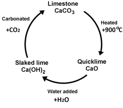
also known as calcium hydroxide or slaked lime. This is an alkaline product which has fine powder and pH12. Calcium carbonate is burned in lime kilns (~900 °C) and calcium oxide (quicklime) is obtained. This reaction is reversible and calcium oxide can react with carbon dioxide for forming calcium carbonate, see Eq. 3. Slaking is the process of converting quicklime (CaO) to hydrated lime (calcium hydroxide) by adding water, as shown in the (Eq. 4) [14]
CaCO3 CaO + CO2 (Eq. 3)
Ca(OH)2 CaO + H2O (Eq. 4)
When lime is mixed with water, it forms calcium hydroxide. The reaction of calcium hydroxide with carbon dioxide is faster, producing a mortar that hardens more quickly, see Eq. 5.
13
It forms Calcium Carbonate (CaCO3) again and the called lime cycle is closed, see
Figure 5.
Ca (OH)2 + CO2 CaCO3 + H2O (Eq. 5)
Air lime or hydrated lime (calcium lime and dolomitic lime) gets harder in air by reacting with atmospheric carbon dioxide. That is why this is an aerial binder. The hydrated lime is commercially available in two versions: putty lime and hydrated lime. Lime putty can be made from either type of lime, and is made by adding an excess of water to quicklime. Hydrated lime is made by adding the exact amount of water. Within EN 459-1:2001 there are two types of air lime which are classified as following (see Table 3).
Table 3-Types of building lime and classification.
Type of Building Lime Type Classifications
Calcium Lime CL90, CL80, CL70
Dolomitic Lime DL85, DL80
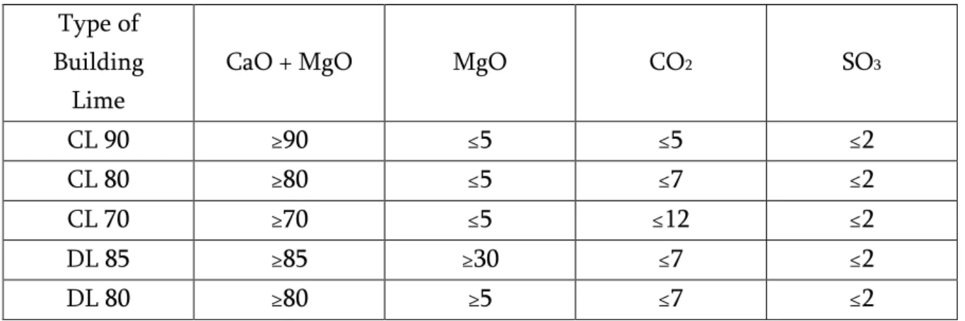
Within EN 459-1:2001 the classes of Calcium Lime and Dolomitic Limeare defined by their percentage of lime content (CaO + MgO) as shown on Table 4.
Table 4-The classes of calcium lime and dolomitic lime.
Type of Building
Lime
CaO + MgO MgO CO2 SO3
CL 90 ≥90 ≤5 ≤5 ≤2
CL 80 ≥80 ≤5 ≤7 ≤2
CL 70 ≥70 ≤5 ≤12 ≤2
DL 85 ≥85 ≥30 ≤7 ≤2
DL 80 ≥80 ≥5 ≤7 ≤2
2.2.4. Hydraulic Lime
The raw material for hydraulic lime is a limestone (CaCO3) which contains calcium
14
the water. More hydraulic lime gets more strength, but less flexible and breathable. There are two types of hydraulic lime three classes within (EN459-1) see Table 5.
Table 5-Types and classification of hydraulic lime.
Type of Building Lime Type Classification Natural Hydraulic Lime NHL5, NHL3.5, NHL2
Hydraulic Lime HL5, HL3.5, HL2
It is noteworthy, that natural hydraulic lime and hydraulic lime are measured by their minimum compressive strength in MPa. Moreover, the compressive strength bands for natural hydraulic lime and hydraulic lime are based on 28 day results and have broad tolerances, because of limits on the accuracy of the measurement equipment and testing error. The Table 6 presents classes of hydraulic lime within EN 459-1:2001.
Table 6-Classes of hydraulic lime within EN 459-1:2001.
Type of Building
Lime Type Classification
Compressive Strenght (MPa) at
28 day Natural Hydraulic
Lime or Hydraulic Lime
NHL2 or HL2 ≤ 2 to ≤ 7 NHL3,5 or HL3,5 ≤ 3.5 to ≤ 5
NHL5 or HL5 ≤ 5 to ≤ 15
2.2.5. Metakaolin
Metakaolin belongs to the pozzolanic additives. Metakaolin (MK) is a alumin-silicate pozzolan, dehydroxylated form of the clay mineral kaolinite at temperatures of from 550 to 650 °C. Metakaolin can be combined with calcium hydroxide to form hydrates and this contributes to improving properties of mortar and concrete, see chemical equation in the Eq. 6. [15].
Al2O3•2SiO2•2H2O = Al2O3•2SiO2 + 2H2O (Eq. 6)
The major chemical components of metakaolin (Table 7) are oxides as SiO2, Al2O3 and
in smaller quantities the oxides Fe2O3, TiO2, Na2O and K2O and as it noticed it is similar
15
Table 7-Chemical composition of metakaolin(HRM).
Chemicals Percentage (%)
SiO2 62.62
Al2O3 28.63
Fe2O3 1.07
MgO 0.15
CaO 0.06
Na2O 1.57
K2O 3.46
TiO2 0.36
LOI 2.00
Metakaolin helps to increase following aspects of cement and concrete [17]: -Flexural and compressive strength
-Density
-Chemical resistance -Alkali-silica resistance
Metakaolin is available in many different varieties and qualities. Some of them also provide special reactivity. Metakaolin is a valuable admixture for concrete or cement applications because it provides many specific features. When is used as a partial replacement substance for cement in concrete, it reacts with Ca(OH)2 one of the
by-products of hydration reaction of cement at ambient temperature and produces in additional C-S-H gel which results in increased strength and lower porosity and permeability (because there is less Ca(OH)2 to be removed by leaching). The chemical
reactions are given below Eq. 7, 8 [6] [18] [19].
Cement + Water = C-S-H gel + Ca (OH)2 (Eq. 7)
Ca (OH)2 + Metakaolin = C-S-H gel (Eq. 8)
16
Portland cements, reducing the quantity of CH in the hydrated cement paste will limit the effects of this form of sulphate attack[17].
Metakaolin combines with the calcium hydroxide to produce additional cementing compounds. Metakaolin is generally whiter than other pozzolans. Whiteness is most important advantage over other pozzolans. Due the white colour it does not let the colour of white concrete made with white Portland cement change. Improving the consistency of mortars and concretes allows to produce high quality dry mixture. In recent years metakaolin has been used much often than ever as a mineral admixture for getting more strength and durable concretes. Sabir (2001) has recently reported a comprehensive review of the studies on the use of the metakaolin as a partial pozzolanic replacement for cement in mortar and concrete[20].
2.2.6. Superplasticizers and Plasticizers
Superplasticizers (SP) are chemical admixtures which are polymers and they are basically used in concrete or mortar processing as a dispersants to avoid aggregation and improve the flow characteristic of concrete such as increase the rheological properties of hardening pastes. The extra water is trapped in the solid structure and increases porosity and reduces strength. This can be compensated by superplasticizers which interfere with the fast hydration reactions of C3A and C3S which cause rapid
17
Admixtures are used to [23]: Congested reinforcement; Self-leveling consistence;
For high-strength concretes by decreasing the water/cement ratio as a result of reducing the water content by 15–25%;
Improved resistance of hardened concrete to the action of freezing and thawing; For improved cohesion and handling properties (workability), especially in
harsh or lean mixes;
Increased cohesion reduces segregation and bleeding, especially when a mix lacks fines;
The superplasticizer has a considerable impact on the various properties of concrete both in fresh and hardened forms due to the following facts [16].
Reduction in interfacial tension.
Multilayered adsorption of organic molecule.
Release of water trapped amongst the cement particles. Retarding effect of cement hydration.
Change in morphology of hydrated cement.
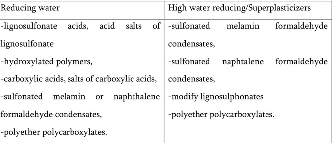
To obtain high-performance water reducing additives is being used and the types are shown in Table 8 [24].
Table 8- Types of additives water reducing/ high water reducing
Reducing water High water reducing/Superplasticizers -lignosulfonate acids, acid salts of
lignosulfonate
-hydroxylated polymers,
-carboxylic acids, salts of carboxylic acids, -sulfonated melamin or naphthalene formaldehyde condensates,
-polyether polycarboxylates.
-sulfonated melamin formaldehyde condensates,
-sulfonated naphtalene formaldehyde condensates,
18
19
Table 9-Information available in the technical data sheet from the producers[26].
Grout Description
Mape-Antique I, from Mapei
Super-fluid, salt resistance, fillerized hydraulic binder, based
on lime and eco-pozzolan, for making injection slurries for
consolidation masonry
Albaria Iniezione from BASF
It is a lime pozzolanic premixed grout without cement with a fine
grain (less than 12 μm) high fluidity and excellent workability Calce per
Consolidamento from Cepro
Is a compound for structural consolidation injections on
masonry at low pressure
Lime-Injection from Tecnochem
Is a binder ideal for injection consolidation of brick masonry,
or stone Its hydraulic setting is fundamentally based on lime-silica microactive reaction and in
the presence of hydraulic lime free of harmful soluble salts
2.4. Durability of Construction Materials – Chemical Resistance
20
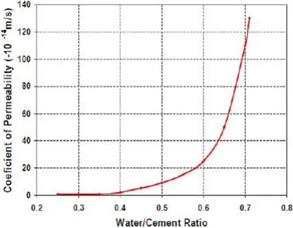
materials and changes in its functional properties. During ageing process, physical or chemical degradation occurs. Solar radiation, temperature variations, mechanical stresses, water, oxygen, pollutants etc. are examples of degradation agents [27]. For durability of materials important parameters are permeability and porosity, and chemical composition of material. Permeability of the concrete is basically dependent on the water/cement ratio. The relationship between the coefficient of permeability and the water/cement ratio is presented in Figure 6 [6], so if ratio is low that means there is low permeability. If porosity in the materials is high durability decreases.
Figure 6-Relationship between permeability and porosity.
21
Table 10– Salt types.
Cations (+) Anions (–)
Sodium (Na+ ) Chloride (Cl- )
Potassium (K+ ) Sulphate (SO4 2-)
Magnesium (Mg2+) Nitrate (NO32-)
Calcium (Ca2+) Carbonate (CO32-)
Salt attack problems in walls commonly are being produced by sodium sulphate, calcium sulphate (gypsum) and sodium chloride. Combination of permeable masonry, moisture, soluble salt, and evaporation are an important part of sulphate attack process. The effect of salt attack on masonry material and structures can be present in different forms, i.e., efflorescence, scaling, cracking, crumbling, and softening [29].
2.4.1. Evaluation of Sulphate attack Resistance – Literature Survey
Sulphate attack (salt crystallisation) is a complex process that injures masonry structures (Figure 7). The final result of sulphate attack can be excessive expansion, cracking, loss of strength and deterioration of the material [30]. The crystallization of soluble salts in porous construction materials is an important weathering process contributing to the decay of masonry, cement and mortar in a range of environments.
Basically the salt crystallization mechanism is affected by the properties of the salt solution, the climatic conditions and the properties of the substrate. Source of sulphates can be external or internal, and the damage effect can be chemical in nature, due to alteration of hydration of products, or physical in nature, due to phase changes in the penetrating sulphate solution.
22
Sulphates can enter masonry materials via following sources[28] [29] saline soils and groundwater;
sea-spray; air-borne salt; air pollutants;
inorganic garden fertilisers;
biological-pigeon droppings, micro-organisms, leaking sewers; salt naturally occurring in the stone, brick clay, or mortar sand; salty water used for puddling brick clay or mixing mortar; salts used for de-icing roads in cold climates;
cleaning compounds that contain (or react to produce) salts in walls.
In groundwater or soil sample commonly mixed sulphates can be found. There are many types of sulphates that begets damages in concrete and in masonry. The main reaction products are gypsum, ettringite, thaumasite, brucite and silica gel. The most common types of sulphates are the sodium, calcium and magnesium of sulphate attack. There is more than one theory proposed to identify the mechanism of cementitious material deterioration due to physical sulphate attack:
(1) Solid volume change, (2) Salt hydration distress, and (3) Crystallization pressure [31]. There are three key chemical reactions between sulphate ions and hardened cement pastes. These reactions are:
recrystallisation of ettringite; formation of gypsum;
decalcification of the main cementitious phase (C-S-H).
Waters containing sulphates react with hydration products of the tri-calcium aluminate (C3A) phase of Portland cement, and with calcium hydroxide (Ca(OH)2) to
23
paste and formation of ettringite and gypsum but of course this is being discussed yet. Sodium sulphate (Na2SO4) can react with calcium hydroxide (Ca(OH)2) to produce
gypsum (CaSO4•2H2O), and sodium hydroxide (NH) according to the following reaction
(Eq. 9)[32].
Ca(OH)2 + Na2SO4 + 2H2O —› CaSO4•2H2O + 2NaOH (Eq. 9)
The gypsum forming according to the reaction (9) can react further with aluminate unhydrated tricalcium aluminate to produce ettringite (3CaO•Al2O3•3CaSO4•32H2O)
according to the following equation (Eq. 10).
3CaO•Al2O3 + 3(CaSO4•2H2O) + 26H2O = 3CaO•Al2O3•3CaSO4•32H2O (Eq. 10)
As it is known the formation of ettringite depends on temperature and pH of solution. From Figure 8 it is possible to point out that gypsum becomes stable at lower sulphate concentrations with increasing temperature, significant change is being noticed started at 50°C degree.Until 50°C dominate the ettringite phase [8].
Figure 8-Effect of temperature on sulphate-bearing phases stability [8].
24
Figure 9-Ettringite stability in alkaline environments as a function of pH and sulphate ion concentration
[33].
Between pH values of 12.45 and 12.7, the sulphate concentration slowly increases, whereas it rises dramatically from that level on. In solutions in which sodium ions are the counterpart of the hydroxide ions, the precipitation of gypsum can take place until pH values of approximately 12.9. Beyond that mark, a further increase of the sulphate concentration is unable to lead to the formation of gypsum. Concerning ettringite, ettringite is not stable in an environment with pH value below 11.5-12.0. At this low pH range, ettringite decomposes and forms gypsum [9].
25
The sodium sulphate phase diagram is shown in Figure 10 [36]. There are three crystalline phases known for sodium sulphate: the anhydrous phase Na2SO4
, also called thenardite, and two hydrous phases: Mirabilite, Na2SO4•10Η2O
, also called decahydrate
and heptahydrate, Na2SO4•7Η2O, which is a metastable phase [37].
Figure 10-The sodium sulphate phase diagram [36].
About 50 salt types commonly appear on buildings. Characteristically, the salt types have very different physical and chemical properties.Sodium sulphate is known to be a salt that causes the worst crystallization decay on porous materials and has become widely used in accelerated durability testing [9]. Sodium sulphate is known example for appearing as thenardite (Na2SO4) when water-free and being able to change to the
water-rich salt phase mirabilite (Na2SO4•10H2O) [38]. Thenardite (Na2SO4) is the
anhydrous phase and it is reported to sediment instantly from solution at temperatures above 32.4C, below this temperature stable phase is the mirabilite (Na2SO4•10H2O) that
quickly dehydrates and it depends humidity and below 71% (20 °C) to form thenardite. Thernardite will rehydrate to mirabilite if the humidity rises over 71%. Sodium sulphate heptahydrate (Na2SO4•7H2O) has been described as precipitating at
26
2.4.2. Evaluation of chloride attack Resistance – Literature Survey
Chloride ions ingress of the masonry materials may devote initiation. Most popular chloride salt is sodium chloride . Many factors influence chloride induced corrosion. The factors are grout mix properties, exposed environment, cure practices, and importantly water/cement (w/c) ratios. The transport of chlorides is influenced strongly by the exact sequence of wetting and drying.When salts first disrupt masonry they enlarge the pores slightly [40][41][6]. After a cycle of wetting and drying, salts fill the enlarged pores and the new crystal growth further disrupts the masonry and enlarges the pores some more. The main mechanisms for chloride transport in concrete are capillary suction, diffusion, permeation and migration [42].Chloride can penetrate into concrete by the effect of: [6]
Exposure to seawater spray or direct contact with seawater wetting;
Application of de-icing to combat the build-up of snow and ice on transport infrastructures;
Exposure to chemical substance;
Internal contamination of chlorides in grout mixture.
The rate of chloride penetration into concrete is affected by the chloride binding capacity of the masonry materials. A portion of the chloride ions reacts with the concrete matrix becoming either chemically or physically bound, and this binding reduces the rate of diffusion. The chloride binding capacity is controlled by the cementing materials used in the concrete. The inclusion of supplementary cementing materials affects binding, though the exact influence is unclear. Also, the C3A content
of the cement influences its binding capacity, with increased C3A content leading to
increased binding [43].Chloride binding is a significant factor related to reinforced masonry durability for three reasons:
reduction of the free chloride concentration in the vicinity of the reinforcing steel will reduce the risk of corrosion;
27
formation of calcium chloroaluminate results in a less porous structure and slows down the transport of Cl- ions) .
The establishment of the chloride threshold level has been one point of increasing interest. However, this parameter is affected by a large number of characteristic factors, such as: [44]
the interstitial solution chemistry and pH; water to cement ratio;
material composition, namely, cement type use of additives, such as fly ash and other mineral admixtures;
pore and capillary structure;
curing period and curing and exposure temperature.
28
3.
Chapter 3
–
Experimental Program
3.1. Materials and Preparation of Specimens
The experimental research presented in this thesis involved the preparation and testing of specimens of two kinds of grouts. One is a commercially available grout from Mapei, Mape Antique I (named grout CA).The second grout (named a grout LB) is a laboratory formulation with cement, metakaolin, hydrated lime, water and a superplastizier. All the procedures necessary to the preparation of samples were performed in the Materials Laboratory of Polytechnic Institute of Bragança, Portugal.
For the preparation of first grout (CA) were mixed 10 kg of commercial available grout and 3.5 L of water. It means that ratio of water to binder (w/b) is 0.35. After mixing 10 minutes, the obtained blend was passed through a sieve. After this, the blend was filled into prismatic moulds with dimensions 4×4×16 cm3, see Figure 11.
Figure 11-Filled blend of commercial grout in the moulds.
After these steps the specimens were kept at room temperature about 48 hours before being available (Figure 12).
Figure 12-Available concretes of grout CA.
29
for the preparation of laboratory grouts. The first hydrated lime, metakaolin, white cement were mixed with water then during mixing plasticizer added. Again, it was mixed during 10 minutes, thereafter passing trough sieve and the obtained blend fill same prismatic moulds (4×4×16 cm3) (Figure 13).Then, they were kept also at room
temperature about 48 hours. The total numbers of specimens were 42 (21 from grouts CA and 21 from grouts LB).
Figure 13-Filled blend of LB grout in the moulds.
Then the concretes were put in the humidity chamberwhere temperature is 20 °C and humidity 90-95 %. Specimens were kept in humidity chamber for 90 days. Before the starting experiment all specimens were dried to constant mass at 105 °C for 18 hours and were measured the dimensions (Length(L), Width(W), Height(H)) using a digital calliper. The weights (M) of the specimens were measured with digital scale and compressive strength tests were done with a compressive testing machine. From dimensions of the samples it was possible to calculate volume of prismatic samples and then was used equation of bulk density whose formula is shown in Eq. 11, where M (g) is the weight and V (cm3) is the volume of specimen. All these obtained results are
shown in Table 11 and Table 12.
30
Table 11-Initial information (weight, volume and bulk density and) of the commercial specimens (CA).
Grout Weight(g.) V (cm3) ρ(g/cm3) CA1 CA2 CA3 CA4 CA5 CA6 CA7 CA8 CA9 CA10 CA11 CA12 CA13 CA14 CA15 CA16 CA17 CA18 CA19 CA20 CA21 415.9 418.2 414.5 420.2 421.1 419.5 433.3 409.6 422.2 419.8 407.8 404.7 418.2 422.9 419.7 409.3 419.2 425.3 427.3 411.2 413.8 251.92 249.03 249.46 253.95 249.13 248.19 252.28 250.73 245.84 252.28 245.66 246.21 246.39 248.49 248.91 250.35 247.34 252.46 247.25 251.01 244.48 1.65 1.68 1.66 1.66 1.69 1.69 1.72 1.63 1.72 1.66 1.66 1.64 1.70 1.70 1.69 1.64 1.70 1.69 1.73 1.64 1.69 Averages
31
Table 12-Initial information (weight, dimension, volume and bulk density) of the lab-specimens (LB).
Grout Weight(g.) V (cm3) ρ(g/cm3) LB1 LB2 LB3 LB4 LB5 LB6 LB7 LB8 LB9 LB10 LB11 LB12 LB13 LB14 LB15 LB16 LB17 LB18 LB19 LB20 LB21 338.90 327.01 330.96 337.08 331.70 348.87 330.54 333.70 333.63 343.24 332.67 352.02 346.32 334.38 347.63 344.52 356.17 353.43 341.84 334.65 348.43 247.02 237.44 242.83 243.59 246.37 249.78 240.21 244.51 242.51 246.12 243.83 247.75 245.37 240.89 245.02 243.02 249.71 250.59 245.16 245.25 250.76 1.37 1.38 1.36 1.38 1.35 1.40 1.38 1.36 1.37 1.39 1.36 1.42 1.41 1.39 1.42 1.42 1.43 1.41 1.39 1.36 1.39 Averages
of values 340.37 245.13 1.39
During the experiment the compressive strength was measured four times. The first was done at the beginning of the experiment, the second after the 13th cycle the third
after the 20th cycle and the fourth, at the end, after the 36th cycle. On Table 13 and
Table 14 are shown the initial results obtained at the beginning and stems from here a information about coefficient of variation (CV) calculating the mean (X ) of each
sample and the standard deviation (s). Formulas to calculate the coefficient of variation are presented below (Eq. 12, 13, 14).
X (Eq. 12)
X
(Eq. 13)
32
Table 13-Initial information (compressive strength and coefficient of variation) of commercial samples.
Sample Strength(MPa) Coefficient of Variation (%) CA1 CA2 CA3 CA4 CA5 CA6 17.54 16.44 15.47 17.57 17.40 16.84 7.9 9.5 5.3 3.9 3.8 9.6 Total average 16.88 Total CV(%) 4.8
Table 14-Initial information (compressive strength and coefficient of variation) of the lab-samples.
Sample Strength Coefficient of
Variation (%) LB1 LB2 LB3 35.97 32.80 35.49 0.6 10.5 7 Total average 34.75 Total CV(%) 4.9 3.2. Reagents
In this study several types of reagents have been used. For wetting-drying process sodium sulphate anhydrous (Na2SO4) and sodium sulphate decahydrate (Na2SO4·10H2O)
were used for preparing 5% sodium sulphate. Magnesium chloride (MgCl2·6H2O),
sodium acetate (CH3COONa·3H2O), potassium nitrate (KNO3) and acetic acid
(CH3COOH; 99%) were also used to prepare the buffer solution which was used during
measurement of sulphates and here sodium sulphate (stock solution) and barium chloride (BaCl2) were used too. Specifications of these reagents are presented on Table
33
Table 15-Specifications of sodium sulphate hydroxide and decahydrate, barium chloride dihydrate,
sodium acetate trihydrate, magnesium chloride 6-hydrate, potassium nitrate and acetic acid.
Chemical
Name Brand Linear Formula
Molar Mass
(g/mol) Appearance Sodium
sulphate hydroxide
Carlo Erba Na2SO4 142.04 Solid
Sodium sulphate decahydrate
Alfa Aesar Na2SO4·10H2O 322.19 Solid
Barium chloride dihydrate
Scharlau BaCl2·2H2O 244,28 Solid
Sodium acetate
trihydrate Scharlau CH3COONa·3H2O 136,08 Solid Magnesium
Chloride 6-hydrate
PanReac MgCl2·6H2O 203.30 Solid
Potassium
nitrate Pronalab KNO3 101.11 Solid
Acetic acid Pronalab CH3CO2H 60.05 Liquid
3.3. Equipment pH meter
A pH meter is a device that measures the pH of a solution by electrode submerged in the solution The pH value is an expression of the ratio of [H+] (hydrogen ion
concentration) to [OH‐] (hydroxide ion concentration). In this study, pH meter from
34
Figure 14-pH meter.
Below on Table 16 are shown technical specifications of equipment.
Table 16–Technical specifications of used pH meter.
pH
Range
basic mode: -2.00 to 16.00 pH, -2.000 to 16.000 pH; standard
mode: ±1000.0 mV for pH
Electrode Diagnostics
standard mode: probe condition, response time and
out of calibration range
pH Electrode (included)
HI 11310 glass body pH
electrode with 1/8”(3.5mm)
connector and 1 m (3.3’) cable
Environment 0 to 50°C (32 to 122°F); RH max 95% non-condensing
Stirring machine
35
.
Figure 15-Stirring machine
Technical specifications are shown on Table 17.
Table 17-Specifications of used stirring machine.
Rotation Speed 0 to 2500rpm
Orbit 5mm
Spectrophotometer
UV/Vis technique is being used to determine the absorption or transference of UV/Vis light (180 to 820 nm) by a sample. It can also be used to measure concentrations of absorbing materials based on developed calibration curves of the material. Here is used the spectrophotometer from brand JASCO, the model V-530 which belongs to UV/Visible class. See Figure 16.
36
Table 18-Specfications of the spectrophotometer.
Optical system
Double beam, single monochromator with a 1200 grooves/mm concave grating and
modified Rowland mount
Spectral bandwidth 2 nm
Wavelength range 190 - 1100 nm
Light sources
Deuterium lamp for UV range (190-350nm), Halogen lamp for VIS range
(330-1100nm)
Balance
For weighting small quantity of solids the balance from brand KERN, the model ACS 220-4, has been used.
Figure 17–Balance.
Specifications are listed below on Table 19.
Table 19-Specifications of the balance for weighting reagents
Weighing range (max) 220 g
Stabilization time 3 sec.
Humidity of air 20 ~ 85 % relative Weighing plate, stainless steel ø 91mm
Ovens
37
Figure 18-Oven Binder FP115 Figure 19-Oven Binder FP720
Table 20- Specifications of the ovens
Specification FP115 FP720
Brand Binder Binder
Temperature range 5 °C above ambient temperature
to [°C]
300 300
Chamber Humidity
Using a chamber humidity, it is possible to set the needed humidity and temperature conditions. Here was used chamber from brand Kide.
38
Table 21-Specifications of the humidity chamber
Temperature 202 °C
Humidity 90-95%
Compressive test machine
In this study the mechanical property compressive strength was just obtained. For getting information about compressive strength, a compressive test machine from brand Matest with maximum force3000 KN has been used.
Figure 21–Compressive testing machine. Figure 22- Testing of specimen. Table 22-Specifications of the compressive machine.
Maximum load capacity(kN) 3000
Platen dimensions(mm) 510×310
Gauges diameter (mm) 300
Digital balance
39
Figure 23-Digital balance.
Digital calliper
The length (L), width (W) and height (H) of prismatic specimens were measured using a digital calliper.
Figure 24-Digital calliper.
3.4. Preparation of sulphate solution
Preparation of sodium sulphate solution 5%
In this study, it was necessary to prepare a sodium sulphate solution with 5% (50 g/L) of solute, to immerse grout samples in it. That means 50 g of sodium sulphate anhydrous (Thenardite, Na2SO4) in one litre or 113.4g sodium sulphate decahydrate
(Mirabilite, Na2SO4·10H2O) per litre. First of all, it is needful to weight solid quantity
40
Figure 25-Used sodium sulphate solution during of the experiment.
3.5. Wetting and Drying Cycles
The durability of masonry structures is directly related with environment conditions and considering this, for this study a wetting-drying process was used with total duration of 36 cycles.It is known that, according to Moukwa (1990), cyclic wetting and drying allows for deeper penetration of aggressive ions and according to Yeomans (1994) can lead to corrosion rates 20 times higher than exposure to a continuous salt solution [46]. Before the starting experiment all specimens were dried to constant mass at 105 °C for 18 hours. At the beginning was done 5 cycles using 6 hours for wetting of samples immersed in sodium sulphate solution 5% at room temperature, and 18 hours for drying in the oven of specimens at 20 °C and after each cycle weight measuring was done. At the end of 5th cycle, each group was split into two and then the first half was
dried at 20 °C and the second at 50 °C.
3.6. Measurement of Compressive Strength
41
(Eq. 15)
For the beginning in Eq. 15 is known surface area (A) 4×4cm2 and after testing by
machine applied force (F) measured in kN could be obtained. Compressive test was done four times. The first was done at the beginning of the experiment, the second after the 13th cycle, the third after the 20th cycle and the fourth at the end, after the 36th
cycle. Of course every time was indispensable to calculate surface area of sample because after a lot of wetting-drying cycles it loses some quantity of material from surface. At the beginning was planned to carry out test taking 3 samples of each type grout but having a small deviation in test, it went with following numbers of specimens, see on Table 23.
Table 23-Used specimen numbers at each cycle.
Cycle Specimen A Specimen B
0 CA1,CA2,CA3,CA4,CA5,CA6 B1,B2,B3
13 CA7,CA8 (20 °C) CA14,CA15(50 °C) LB4,LB5,LB6(20 °C) x 20 CA9,CA10 (20 °C) CA16,CA17(50 °C) LB7,LB8,LB9(20 °C) x
36 CA11,CA12,CA13(20 °C) x x x
Each time specimens were divided into two pieces and was done compressive test obtaining two results from one specimen for making average of compressive strength in MPa and to calculate the coefficients of variation (CV) in % (see Table 24 , 25).
3.7. Measurement of pH
Measuring pH is necessary to know the degree of acidity or basicity of a solution. During this study, a sodium sulphate (5%) solution was used for which it was necessary to control the pH. Before using in the wetting experiments obtained solution of sodium sulphate was subjected to pH measuring by HANNA pH meter with glass electrode and the obtained pH was 6.8. Then the same action was done every day with taken samples, which have been taken each day until the 12th cycle. After 12th cycle started each tree
42
measuring pH the temperature of solution was allowed to be close to room temperature (approximately 20 °C).
3.8. Measurement of sulphate concentration
Having samples was necessary to determine quantity of sulphate (SO42-).The sulphate
quantity was determined using a spectrophotometer. First of all, a calibration curve was made following the turbidimetric method. Knowing that the sulphate from experiment have concentration higher than 10mg/L it was prepared a buffer solution by dissolving 15 g magnesium chloride (MgCl2·6H2O), 2.5 g sodium acetate (CH3COONa·3H2O), 0.5 g
potassium nitrate (KNO3), and 10 mL acetic acid (CH3COOH; 99%) in 250 mL distilled
water and making up to 500 mL, thereafter a stock solution of anhydrous sodium sulphate (Na2SO4) was prepared dissolving 0.1479 g in 750 mL distilled water and
diluted up to 1000 mL which means that in this solution is contained 100 mg sulphate per litter (1 mL=100μg SO42-).For this measurement is known that sodium sulphate
reacts with barium chloride and forms barium sulphate that precipitates, see Eq. 16.
Na2SO4+BaCl2=BaSO4+2NaCl
(
Eq. 16)The absorbance of the barium sulphates formed has been measured by a spectrophotometer at 420 nm wavelength and the sulphates ion concentration has been determined by comparison of the read of absorbance value each sample with a standard curve. Calibration curve was obtained by preparing series of standards 10, 20, 30, 40, 50 and 100 mg/L (Figure 26).
43
These standards prepared as follows: 10mL of standard sulphate solution was filled to the first volumetric flask, 20 mL to the second, 30 mL to the third, 40 mL to the fourth, 50 mL to the fifth and 100 mL to the sixth. All five flasks were topped up to 100 mL mark with distilled water. Starting the measuring procedure for sulphates concentration determination with spectrophotometer first was done auto zero afterwards blank. Auto zero was done with empty chamber of equipment and then for blank were used two glass cuvettes (washed with distilled water) filled with distilled water and both situated to the chamber. After these two steps was measured the absorbance of sulphate standards doing next steps. Mix 10ml of distilled water with 2 mL of buffer solution and a small spoon of BaCl2 and stirring on the stirring machine 60
seconds. All these all steps were done for measuring sulphate concentration of samples too. But in this study the concentration of sulphate in the sample solution was quite concentrated compared with stock solution, therefore it was diluted 2500 times in order to be in the range of calibration curve. It was taken 4 μL of sample and mixed with 10 mL distilled water and then again 2 mL of buffer solution and a small spoon of BaCl2 and stirring on the stirring machine 60 seconds. Then from calibration curve was
taken slope value and then concentration of samples were calculated.
3.9. Measurement weight and dimensions of prism grouts.
During wetting-drying process, it is possible to have some changes in dimensions and weight of specimens therefore research was done on how the weight and sizes change in time of it. Weight loss and change in compressive strength can be a good indicator of the degree of the aggravation of sulphate attack [47]. Measurement of the weight was done every day, started from the beginning until the end but the dimensions were measured the first time at the beginning, the second after 13th cycle, the third after 20th
cycle and the fourth at the end after 36th cycles like it was done for compressive
44
4.
Chapter 4
–
Results
4.1. Compressive Strength
Results of compressive test of specimens are shown in Figure 27 and Figure 28 and in more detail the compressive test and coefficient of variation (CV, %) are shown in Table 24 and 25. The samples have been dried at 20 °C until 6th cycle then one half
continued at 20 °C and the second half at 50 °C.
Figure 27- Compressive test results of commercial specimens.
Figure 28-Compressive test results of lab-specimens.
The results of commercial specimens of compressive test done are represented in Figure 27. The first point is the result of the initial strength of specimens then after 5th cycle
the specimens (CA, LB) were split into two parts, one part of them started to dry at 20
16.9 17.3 18
11.4 16.4 11.4 10 15 20 25 30 35
0 4 8 12 16 20 24 28 32 36
Com p re ss iv e s tren gth (MPa)
Number of cycles
20C 50C
34.8
29.8 30.7
10 15 20 25 30 35 40
0 4 8 12 16 20 24 28 32 36
Com p re ss iv e s tren gth (MPa)
Number of cycles
45
°C (blue points) and other part at 50 °C (red points) . Up to 13th cycle the results of
strength of specimens at 20 °C and 50 °C are comparable and they were close together. After 20th cycle the specimens dried at 50 °C lost their strength instead at 20 °C which
shows a bit increase of strength. But after this cycle specimens at 50 °C started breaking-down not resisting until the end of the experiment. But at 20 °C they persisted until the end and could carry out a test after 36th cycle. As shown, the result
has decreased compared with a result of 20th cycle obtained. Figure 28 shows
information about the strength of lab-specimens. The first point is the initial strength. At 13th cycle point for 20 °C shows that strength is increased but the 20th cycle point
shows a bit more increased strength compared with 13th cycle strength. And about 50
°C it could not carry out compressive test for LB specimens even after 13th cycle
because during experiment B grout was not resistant to sulphate attack compared with CA grout and they started to brake-down earlier (after 11th cycle) than commercial
grout specimens. That is why there is no information on Figure 28 about 50 °C degree.
Table 24-Compressive test results of commercial specimens.
Time and
temperature Specimen
Strength(MPa) and coefficient of variation (CV, %) of
each specimen
Total average(MPa) and (CV, %) of the
specimens Initial CA1 CA2 CA3 CA4 CA5 CA6 17.54(7.9) 16.44(9.5) 15.48(5.3) 17.58(3.9) 17.40(3.8) 16.84(9.6) Average 16.88 CV 4.8
13th cycle (20 °C) CA7
CA8
18.72(9) 15.89(12.3)
Average 17.30 CV 11.5 13th cycle (50 °C) CA14
CA15
16.38(2.3) 16.40(12.1)
Average 16.39 CV 0.1 20th cycle (20 °C) CA9
CA10
16.75(13.8) 19.21(6.4)
Average 17.97 CV 9.6 20th cycle (50 °C) CA16
CA17
10.75(24.4) 12.05(21.1)
Average 11.4 CV 8
36th cycle (20 °C)
![Table 1-Types of Cement, within European standard EN 197-1 [8].](https://thumb-eu.123doks.com/thumbv2/123dok_br/16812933.750978/24.892.154.708.640.1151/table-types-cement-european-standard-en.webp)
![Figure 8-Effect of temperature on sulphate-bearing phases stability [8].](https://thumb-eu.123doks.com/thumbv2/123dok_br/16812933.750978/37.892.226.638.683.962/figure-effect-temperature-sulphate-bearing-phases-stability.webp)
