Introduction
Europe’s irst onshore scientiic carbon dioxidestorage testing project CO2SINK (CO2 Storage by Injection into a Natural saline aquifer at Ketzin) is performed in a saline aquifer in NE Germany. The major objectives of CO2SINK are the advancement of the science and practical processes for underground storage of carbon dioxide, and the provision, and the provision and the provision of operational ield results to aid in the development of stan-dards for CO2 geological storage. Three boreholes (one injec-tion well and two observainjec-tion wells) have been drilled in 2007, each to a depth of about 800 m. The wells are com-pleted as “smart” wells containing a variety of permanent downhole sensing equipment, which has proven its function-ality during its baseline surveys. The injection of CO2 is scheduled for spring 2008 and is intended to last up to two is intended to last up to two intended to last up to two years to allow for monitoring of migration and fate of the injected gas through a combination of downhole monitoring with surface geophysical surveys. This report summarizes well design, drilling, coring, and completion operations., and completion operations. and completion operations.
Since the publication of the Intergovernmental Panel on Climate Change Report (IPCC, 2005), carbon dioxide cap- cap- cap-ture and storage, including the underground injection of CO, including the underground injection of CO including the underground injection of CO2 through boreholes, became a viable option to mitigate, became a viable option to mitigate became a viable option to mitigate atmospheric CO2 release. One of the major goals for the immediate future is to investigate the operational aspects of CO2 storage and whether the risks of storage can be success-fully managed.
CO2SINK is the irst European research and development project on in situ testing of geological storage of CO2 in an onshore saline aquifer (Förster et al., 2006). Key objectives of the project are to advance understanding of and develop practical processes for underground storage of CO2, gain operational ield experience to aid in developing a harmonized regulatory framework and standards for CO2 geological storage, and build conidence towards future set in “projects of that kind”.
The CO2SINK site is located near the town Ketzin to the west of Berlin, Germany (Fig. 1). The plan is to inject into a saline aquifer over a period of two years a volume of approxi-mately 60,000 t of CO2. For this purpose, one vertical injec-tion well (Ktzi-201) and two vertical observainjec-tion wells (Ktzi-200 and Ktzi-202) were drilled at a distance of 50 m to 100 m from each other (Fig. 1). All three wells are equipped
with downhole instrumentation to monitor the migration of the injected CO2 and to complement the planned surface geo-physical surveys. The injection of CO2 will be interrupted at times for repeated downhole seismics (VSP, MSP), cross-hole seismic experiments, and downhole geoelectrics., and downhole geoelectrics. and downhole geoelectrics.
The preparatory phase for CO2 injection started in April 2004 with a comprehensive geological site characterization and a baseline luid monitoring (Förster et al., 2006). This was followed by a baseline 3-D seismic survey (Juhlin et al., 2007) and the development of a drilling and completion con-cept (Fig. 2) allowing for monitoring during CO2 injection and storage observation.
Geological Background
The CO2SINK site is located in the Northeast German Basin (NEGB), a subbasin of the Central European Basin System. The sedimentary succession in the NEGB is several kilometers thick containing geological formations of Permian to Quaternary age, comprising abundant deep saline aquifers. The CO2 will be injected into the Stuttgart Formation (lowerlower portion, Fig. 3) of Triassic (Middle Keuper) age, into theFig. 3) of Triassic (Middle Keuper) age, into the southern lank of a gently dipping double anticline.
The 80-m-thick target formation rests at about 630–710 m-m-thick target formation rests at about 630–710 mm-thick target formation rests at about 630–710 m-thick target formation rests at about 630–710 mthick target formation rests at about 630–710 m depth at a temperature of about 38°C. The formation is madea temperature of about 38°C. The formation is madetemperature of about 38°C. The formation is made up of siltstones and sandstones interbedded by mudstones deposited in a luvial environment. The reservoir is in sand-stone channels as well as levee and crevasse splay deposits. These channel-(string)-facies rocks alternate with muddyese channel-(string)-facies rocks alternate with muddy channel-(string)-facies rocks alternate with muddy
The CO
2
SINK Boreholes for Geological Storage Testing
by Bernhard Prevedel, Lothar Wohlgemuth, Jan Henninges, Kai Krüger,
y Bernhard Prevedel, Lothar Wohlgemuth, Jan Henninges, Kai Krüger,
Ben Norden, Andrea Förster, and the CO
2SINK Drilling Group
doi:10.04/iodp.sd.6.04.008
Borehole Design
All three wells were designed with the same casing layout,, including stainless production casings equipped with pre-perforated sand ilters in the reservoir section and wired on the outside with a iber-optical cable, a multi-conductorer-optical cable, a multi-conductorr-optical cable, a multi-conductor copper cable, and a PU-heating cable to surface (Table 1). The reservoir casing section is externally coated with a iber-er- r-lood-plain-facies rocks of poor reservoir quality. A
geostatis-tical approach applied to the reservoir architecture (Frykman et al., 2006) pointed towards variable dimensions of the sand-stone bodies and was supported by continuous wavelet trans-forms on 3-D seismic data (Kazemeini et al., 2008).-D seismic data (Kazemeini et al., 2008).D seismic data (Kazemeini et al., 2008).
The Stuttgart Formation is underlain by the Grabfeld Formation (Middle Keuper), which is a thin-bedded mud-stone succession with interbedded marlmud-stone, marly dolo-mite and thin anhydrite or gypsum beds deposited in a clay/mud-sulfate playa depositional environment (Fig. 3�Fig. 3� Beutler and Nitsch, 2005). The immediate caprock of the Stuttgart Formation, the Weser Formation (Middle Keuper),, also is of continental playa type, consisting mainly of ine-grained clastics such as clayey and sandy siltstone that alter-nate with thin-bedded lacustrine sediments, like carboalter-nates, and evaporites (Beutler and Nitsch, 2005). The high clay-mineral content and the observed pore-space geometry of these rocks attest sealing properties appropriate for CO2 capture (Förster et al., 2007). The Weser Formation is overlain by the Arnstadt Formation (Middle Keuper), again of lacustrine character (mud/clay-carbonate playa� Beutler and Nitsch, 2005) with similar sealing properties. The two caprock formations immediately overlying the Stuttgart Formation are about 210 m thick (Fig. 3).
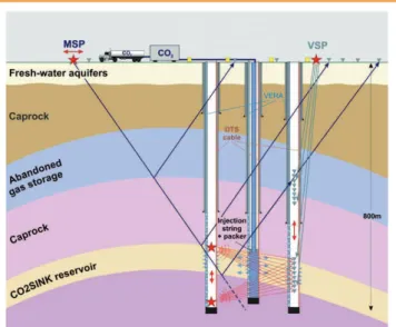
Figure 2. Schematic concept of Ketzin geology, drilling, and geophysical monitoring including moving source seismic profiling (MSP), vertical seismic profiling (VSP), cross-hole seismics, surface 3-D seismics, and surface and cross-hole geoelectrics using a per-manently installed Vertical Electrical Resistivity Array (VERA), and Distributed Temperature Sensing (DTS) (from Förster et al., 2006).
Table 1. Casing Schemes
Depth [m] Diameter [inch] [mm] [lb/ft] Quality Connection
Stand pipe 30 24 610 125.5 4140 welded
Conductor 150 18 5/8 473 87.5 X56 Buttress-BTC
Reserve Casing ca.340 13 3/8 340 54.5 K-55 Buttress-BTC
Intermediate 590 9 5/8 244 36 K-55 Buttress-BTC
Production String 800 5 1/2 140 20 13Cr80 (outside coating) VAM Top
Injection String 680 3 1/2 89 9.3 C-95 (inside coating) TS-8
Figure 3. Condensed geological profile of the Ktzi 200/2007 borehole. Lithological color code: mudstone (magenta), siltstone (green), sandstone (yellow), anhydrite (light blue).
diverter/gas-lare installation on the rig to capture and control unexpected and sudden shallow gas inluxes. As no stranded shallow gas was encountered during drilling (as(asas also conirmed by reconnaissance wire-line logging and surface seismic processing), this pilot drilling was conse-), this pilot drilling was conse-, this pilot drilling was conse-quently skipped for the second and third well. CasingCasingasing (18 5/818 5/8") running and cementation with stinger to surfacerunning and cementation with stinger to surface were performed in all three wells without problems.ere performed in all three wells without problems. performed in all three wells without problems.
In the following 12 1/4" sections, the wells penetrated the Jurassic aquifer systems in which under-balanced pressure regimes were supposed. All wells encountered a minimum of three loss circulation zones between 366 m and 591 m withm and 591 m withand 591 m with cumulative mud losses of 550 m3. The addition of medium- to coarse-grained shell grit to the mud cured the loss of circulation and brought the wells safe to the 9 5/8" casing depth between 588 m and 600 m.m and 600 m.and 600 m.
glass resin wrap for electrical resin wrap for electricalresin wrap for electrical insulation. A staged cementation program was planned around the application of newly devel-oped swellable elastomer packer and stage cementation downhole tools. This technology was pre-ferred over perforation work thatred over perforation work that over perforation work that would have caused unmanage-able risks of potential damage of the outside casing cables.
The 200-m core sections for-m core sections form core sections for detailed reservoir and sealing property investigations were recovered with a 6" x 4" wire-line coring system using polycrystal-line diamond compact (PDC) (PDC)(PDC) core bits. The 6 1/4" core hole sections were enlarged to 8 1/2", and the wells inally deepened below the reservoir zone to accommodate suficient sensor spacing for installation of behind-casing sensor arrays.
Drilling and
Completion Operations
Constructing three wells close to each other and with such a dense sensor and cable popula-tion requires detailed planning. For this purpose, high-end oilield QHSE (Quality, Health, Safety, Environment) manage-ment tools were applied, such as “drill well on paper” (DWOP), hazardous operation identiica-tion, repeated incident report-ing, post job analysis, and risk management.
Drill site construction started in December 2006, and the drilling operation commenced on 13 March 2007 with the13 March 2007 with theMarch 2007 with the mobilization of a truck-mounted and top-drive equipped rotary drill rig. All the Ketzin wells were drilled with a shale inhibited KCl-water-based mud system, with the exception of-water-based mud system, with the exception ofwater-based mud system, with the exception of the top-hole section in the fresh-water aquifers, where a K2CO3-water-based system was required by the authorities. Both drill muds were conditioned at 1.05–1.16 gcm-33 density. In order to avoid potential risks from environmental hazards, the project further implemented a “shallow gas” procedure in this well section to avoid spills when the wells would encounter high pressurized shallow gas from the past gas storage activity. For this purpose, the top-hole section of the irst borehole was pre-drilled with a blow-out preventer/
Figure 4. Drilling design and well completion of the Ktzi 201/2007 borehole. Yellow line indicates DTS and ERT cables with location of ERT electrodes (yellow pluses). Sandstone reservoir intervals are shown in green.
50
Metres below ground
level Metresbelow
ground level
100
150
200
250
300
350
400
450
500
550
600
650
700
750
18 5/8” @ 49 m 24 7/8” @ 30 m
9 5/8”
TOC: 675 m
Stage Cementing Tool 13 3/8” @ 171 m
Casing Shoe: 589 m TOC: 69 m
TOC:465 m
CO Sink Ktzi-201/2007 Well Construction
2Swell Packer Elements
5 1/2” Filter Screens 5 1/2” Filter Screens
TD: 755 m
620 580
640
660
680
700
720
740
760 600 560
Casing Shoe 9 5/8”
TD 755 m
Stinger Packoff TOC: 675 m
5 1/2” Insulated Casing
Float Shoe
Filter Screens Insulated Stage Cementing Tool 5 1/2” Production Packer
Swell Packer Elements
Viscous Plug
Drill Mud
Cement
5 1/2” Insulated Casing 5 1/2” Blank Casing
Using the DTS technology, quasi-continuous tempera-ture proiles can be measured on-line along the entire length of the wells with high temporal and spatial resolution (Förster et al., 1997� Büttner and Huenges, 2003). The permanent installation of DTS sensors behind the
casing (Hancock
et al., 2005� Henninges et al., 2005) offers the advantage of full
access to the well during technical operations, which, for example, allows control of the process of casing cementation (Henninges and Brandt, 2007). The borehole temperature data will primarily serve in the delineation of physical prop-erties and of the state of the injected CO2. To enhance the thermal signal and improve the monitoring of brine and CO2 transport, successive thermal perturbation experiments (Freifeld et al., 2006) will be performed, using the electrical heater cable installed adjacent to the DTS cables. VERA pro-vides data on the CO2 saturation employing the Electrical Resistivity Tomography (ERT) method. Each of the VERA arrays covers an interval of about 140 m centered in the injec-ered in the injec-red in the injec-tion horizon and consisting of ifteen electrodes spaced atifteen electrodes spaced at electrodes spaced at about 10-m intervals. The P/T-sensor installed at the bottom-m intervals. The P/T-sensor installed at the bottomm intervals. The P/T-sensor installed at the bottom of the injection string above the packer system will continuously monitor the downhole pressure and tempera-monitor the downhole pressure and tempera-ture changes during injection. Data will be transferred viawill be transferred viatransferred viared via via optical iber attached to the injection string.
The inclusion of the permanent downhole sensors into the well completion required a selection of suitable completion components and procedures. Custom-made casing central-izers were used for outside-casing installation of sensor cables, for centralization of the casing inside the borehole,ation of the casing inside the borehole, the casing inside the borehole, and for protection of cables from mechanical damage during installation (Fig. 5). The 8 1/2" borehole diameter in the lower reservoir sections allowed for suficient clearance within the annular space between casing and borehole wall and thus for a safe installation of the downhole sensors.fe installation of the downhole sensors.e installation of the downhole sensors. Within the 140-m zone, where the VERA electrodes are-m zone, where the VERA electrodes arem zone, where the VERA electrodes are placed, the steel casing was electrically insulated outside using a iberglass coating.erglass coating.rglass coating.
After an on-site installation test had been conducted, the installation of the DTS and VERA cables (Fig. 5) and electrodes in the Ktzi 200, 201, and 202 wells was performed on 5 May, 5 July, and 18 August 2007. After careful installa-5 May, 5 July, and 18 August 2007. After careful installa-May, 5 July, and 18 August 2007. After careful installa-, 5 July, and 18 August 2007. After careful installa- July, and 18 August 2007. After careful installa-18 August 2007. After careful installa-August 2007. After careful installa-tion operainstalla-tions of up to 18–24 h durainstalla-tion, the cables were The lower part of Weser Formation and the entire Stuttgart
reservoir section were cored with a specially designed CaCO3-water/polymer drilling mud (1.1 g cmwater/polymer drilling mud (1.1 g cm cmcm-33). In the irst well, a total of 100 m core was drilled in thirty-nine core runs,thirty-nine core runs, core runs,, and an average recovery of 97� was achieved. In the second well 80 meters of core was retrieved in thirty-one runs (100�thirty-one runs (100� runs (100� recovery). In the third well only the top 18 m of the Stuttgart Formation was cored with the same excellent performance. The 6 1/4" core hole section was then enlarged to 8 1/2then enlarged to 8 1/2enlarged to 8 1/2", and the wells inally deepened below the reservoir into the Grabfeld Formation.
Stainless steel 5 1/2" production casings (Fig. 4) were 4) were4) were installed and cemented in all wells with sensors and cables on the outside. The cables were terminated and fed pressure tight at the wellhead to the outside through the drilling spool below the casing slips. The cement selected in all casing cementations was standard class-G with fresh water and no additives (SG = 1.98 kg L L-1), with the exception of the plug cementation, for which a specially designed CO2-resistant class-G salt cement was selected.
The CO2 injection well was completed with a gas-tight and internally coated production tubing, including a permanent production packer above the injection horizon, a iber-opticer-opticr-optic pressure and temperature mandrel/gauge arrangement above the packer and a wire-line-retrievable subsurface a wire-line-retrievable subsurfacea wire-line-retrievable subsurface safety valve at 50 m depth below the well head. The optical cables and hydraulic safety valve actuation lines were clamped to the outside of the production tubing and fed pres-sure tight to the outside at the tubing hanger adaptor below the Christmas tree gate valves.Christmas tree gate valves. tree gate valves.
Permanent Downhole Sensors for
hole Sensors for
ole Sensors for
Monitoring of CO
2Geophysical monitoring techniques are applied in CO2SINK to delineate the migration and saturation of injected CO2 (Fig. 2). The injection well and the two observa-tion wells are equipped with state-of-the-art as well as newly developed geophysical sensors. The data from this perma-nent downhole monitoring will be interpreted in combination with data from periodic seismic monitoring (VSP, MSP, and cross-hole seismics) and periodic luid sampling and well logging (Reservoir Saturation Tool).
The following permanent components were installed in the boreholes for scientiic monitoring:
• a iber-optic-sensorer-optic-sensorr-optic-sensor cable loop for Distributed cablecable looploop forfor DistributedDistributed Temperature Sensing (DTS� all wells)
• a two-line electrical heater cable (Ktzi 201/2007, Ktzi 202/2007)
• a Vertical Electrical Resistivity Array (VERA) consist-ing of ifteen toroidal steel electrodes, 15-line surface connection cable (all wells)
• optic pressure/temperature (P/T) sensor, iber-optic surface connection cable (at injection string only).
guided into the substructure of the drill rig, and the casing, and the casing and the casing was cemented.
The DTS monitoring allowed online monitoring and con-trol of the cementing operations and provided valuable infor-mation about the positions of the cemented sections during the setting of the cement. This information was veriied by subsequent industry-standard cement-bond logs. The instal-lation of monitoring tools was inished by feeding the cables into the casing spool at the wellhead, which was subsequently pressure-sealed using a stufing box. Preliminary tests of VERA have shown that all electrodes and cables are fully functional.
Field Laboratory
The CO2SINK ield laboratory comprised core-cleaning and core-sealing facilities, a full core imager, and a Geotektekek gamma-ray density core logger. The ield lab was designed to record and describe a high core-run volume within a short handling time to quickly generate the litholog for the drilled boreholes and to identify the reservoir section. This proce-dure was necessary in order to proceed rapidly with decisionrapidly with decisionwith decision making on the selection of the borehole intervals completed with ilter casings through which the CO2 would be injected into the formation or monitored.
In the preparation for unconsolidated sandstone in the Stuttgart Formation, coring was performed with PVC liners in 3-m liner intervals. At the drill rig, liners were cut after-m liner intervals. At the drill rig, liners were cut afterm liner intervals. At the drill rig, liners were cut after orientation marking into 1-m sections, and the cut surface-m sections, and the cut surfacem sections, and the cut surface, and the cut surface and the cut surface geologically described was sealedsealed before before being transferred to the ield lab for analy-ses. Sections contain-ing sandstone were shipped preserved in liners to a commercial
laboratory for
“hot-shot” poro-perm analysis. Reservoir sandstone intervals (Fig. 6) with porosities on the order of 20�–25�,�–25�,–25�, togethertogethertogether with requirements for permanent ERT sen-sor arrangement on the casing, guided the depths at which the wells were completed with ilter screens for CO2 injection and monitoring.
The geological description of core started with the sec-tions of well-cemented mudstone after its cleaning with syn-thetic formation water, reorientation, and scanning unrolled using an optical core scanner. Later, the “hot-shot” reservoir sections were included. From the geological core and cutting descriptions and interpreted petrophysical well logs, stratigraphic-lithologic logs (Fig. 3) were inally generated for all three CO2SINK wells to reine the geological model. For example, the stratigraphic-lithologic logs were used to calibrate the 3-D seismic time sections (Juhlin et al., 2007). Petrographical and mineralogical studies and geochemical analyses from reservoir and caprock were performed to characterize the Ketzin site on micro-scale as a basis for luid-rock-alteration modeling.
Outlook
CO2SINK is the irst project that extensively uses behind-casing installations for a study of the CO2 injection and storage process in a geological medium. In this regard, CO2SINK differs from other scientiic projects of CO2 test storage, such as the Frio experiment in Texas (Hovorka et al., 2006), the Nagaoka experiment in Japan (Kikuta et al., 2004), the ield test in the West Pearl Queen Reservoir in New Mexico (Pawar et al., 2006), and the Otway Basin pilot project in Australia (Dodds et al., 2006).
It is envisaged that the extensive set of data generated by cross-correlation of seismic surface monitoring, well-logging and monitoring, and simulations, will allow for veriication of
a priori scenarios of storage/migration of luids. Emphasis, for example, will be given to the observation of non-isothermal effects in the storage formation during injection as described by Kopp et al. (2006). This type of effect also can occur during leakage from a storage reservoir along a fracture zone as numerically investigated by Pruess (2005). Thus, the observations in progress will contribute to a sound under-standing of the thermodynamic processes of CO2 injection at well-scale as well as in the short and longer term the pro-cesses during CO2 storage at larger scale.
Acknowledgements
s
We would like to thank all partners of the CO2SINK proj-ect for their continued support and contributions that helped to inish the three wells in a healthy and environmentally safe manner. Special thanks go to Shell International and StatoilHydro for their most valuable advice and operational for their most valuable advice and operational support during the planning and drilling phase in Ketzin. Furthermore, thanks go to VNG AG for letting us use. Furthermore, thanks go to VNG AG for letting us use, thanks go to VNG AG for letting us use thanks go to VNG AG for letting us useuse their site at Ketzin and for their local logistical support onKetzin and for their local logistical support on and for their local logistical support on site. The CO2SINK project receives its funding from the European Commission (Sixth Framework Program, FP6) and two German ministries, the Federal Ministry of Economics and Technology (CO2-Reduction-Technologies for fossil fuelled power plants, COORETEC Program), and, and and the Federal Ministry of Education and Research (Geotechnologien Program).
References
Beutler, G., and Nitsch, E., 2005. Paläographischer Überblick. In Beutler, G. (Ed.), Stratigraphie von Deutschland IV, Keuper. Stuttgart (Courier Forschung-Institut Senckenberg, 253),Courier Forschung-Institut Senckenberg, 253),ier Forschung-Institut Senckenberg, 253), Forschung-Institut Senckenberg, 253),ung-Institut Senckenberg, 253),-Institut Senckenberg, 253),itut Senckenberg, 253), Senckenberg, 253),), 15–30.
Büttner, G., and Huenges, E., 2003. The heat transfer in the region ofThe heat transfer in the region of the Mauna Kea (Hawaii) – constraints from borehole tem-perature measurements and coupled thermo-hydraulic modeling. Tectonophysics, 371:23–40.
Dodds, K., Sherlock, D., Urosevic, M., Etheridge, D., de Vries, D., and Sharma, S., 2006. Developing a monitoring and veriication scheme for a pilot project, Otway Basin, Australia..
Proceedings GHGT-8 Conference, Trondheim, Norway,
CD-ROM.
Förster, A., Norden, B., Zinck-Jørgensen, K., Frykman, P., Kulenkampff, J., Spangenberg, E., Erzinger, J., Zimmer, M., Kopp, J., Borm, G., Juhlin, C., Cosma, C.-G., and Hurter, S., 2006. Baseline characterization of the COBaseline characterization of the CO2SINK geological storage site at Ketzin, Germany. Environmental Geosciences, 13:145–161.
Förster, A., Schrötter, J., Merriam, D.F., and Blackwell, D.D., 1997. Application of optical-ibre temperature logging� an exam-ple in a sedimentary environment. Geophysics, 62(4): 1107–1113.
Förster, A., Springer, N., Beutler, G., Luckert, J., Norden, B., and Lindgren, H., 2007. The mudstone-dominated caprockThe mudstone-dominated caprock system of the CO2-storage site at Ketzin, Germany. Proceedings of the 2007 AAPG Annual Convention andof the 2007 AAPG Annual Convention and2007 AAPG Annual Convention and Exhibition, Long Beach, Calif., U.S.A., CD-ROM.Calif., U.S.A., CD-ROM.U.S.A., CD-ROM..S.A., CD-ROM.S.A., CD-ROM..A., CD-ROM.A., CD-ROM.., CD-ROM., CD-ROM.
Freifeld, B.M., Walker, J., Doughty, C., Kryder, L., Gilmore, K., Finsterle, S., and Sampson, J., 2006. Evidence of rapid local-ized groundwater transport in volcanic tuffs beneath Yucca Mountain, Nevada.. Eos Trans. AGU, 87:52:H43A–0480.–0480.0480. Frykman, P., Zinck-Jørgensen, K., Bech, N., Norden, B., Förster, A.,
and Larsen, M., 2006. Site characterization of luvial, incised valley deposits. Proceedings CO2SC Symposium, Lawrence Berkeley National Laboratory, Berkeley, Calif., U.S.A.,Calif., U.S.A.,U.S.A.,.S.A.,S.A.,.A.,A.,.,, 121–123.–123.
Hancock, S., Collett, T.S., Dallimore, S.R., Satoh, T., Inoue, T., Huenges, E., Henninges, J., and Weatherill, B., 2005. Overview of thermal-stimulation production-test results for the JAPEX/JNOC/GSC Mallik 5L-38 gas hydrate produc-tion research well. In Dallimore, S.R., and Collett, T.S. (Eds.), Scientific Results from the Mallik 2002 Gas Hydrate Production Research Well Program, Mackenzie Delta, Northwest Territories, Canada, Geological Survey of Canada,
GSC Bulletin, 585:CD-ROM.
Henninges, J., and Brandt, W., 2007. Evaluation of cement integrity using distributed temperature sensing. Proceedings Engine Workshop 4 “Drilling cost effectiveness and feasibility of
high-temperature drilling”,ISOR, Reykjavik, Iceland, 41p.p..
Henninges, J., Schrötter, J., Erbas, K., and Huenges, E., 2005. Temperature ield of the Mallik gas hydrate occurrence –gas hydrate occurrence –as hydrate occurrence – hydrate occurrence –hydrate occurrence – implications on phase changes and thermal properties. In Dallimore, S.R., and Collett, T.S. (Eds.), Scientific Results from the Mallik 2002 Gas Hydrate Production Research Well Program, Mackenzie Delta, Northwest Territories, Canada,
Geological Survey of Canada, GSC Bulletin, 585:CD-ROM.
Hovorka, S.D., Benson, S.M., Doughty, C.K., Freifeld, B.M., Sakurai,
S., Daley, T.M., Kharaka, Y.K., Holtz, M.H., Trautz, R.C., Nance, H.S., Myer, L.R., and Knauss, K.G., 2006. Measuring permanence of CO2 storage in saline formations – The Frioage in saline formations – The Frioge in saline formations – The Frio – The Frio– The Frio The FrioThe Frio experiment. Environmental Geosciences, 13:103–119. IPCC, 2005. IPCC Special Report on Carbon Dioxide Capture and
Storage. Prepared by Working Group III of the IPCC [Metz,
B., Davidson, O., de Coninck, H.C., Loos, M., and Meyer,O., de Coninck, H.C., Loos, M., and Meyer,de Coninck, H.C., Loos, M., and Meyer,H.C., Loos, M., and Meyer,Loos, M., and Meyer,M., and Meyer,and Meyer,, L.A. (Eds.)]. Cambridge (Cambridge University Press), 442 (Eds.)]. Cambridge (Cambridge University Press), 442 (Cambridge University Press), 442Cambridge University Press), 442), 442, 442 pp.
Juhlin, C., Giese, R., Zinck-Jørgensen, K., Cosma, C., Kazemeini, H., Juhojuntti, N., Lüth, S., Norden, B., and Förster, A., 2007. 3D baseline seismics at Ketzin, Germany: the CO2SINK project. Geophysics, 72(5):B121–B132.(5):B121–B132.5):B121–B132.):B121–B132.:B121–B132.B121–B132.121–B132.–B132.B132.132.
Kazemeini, H., Juhlin, C., Zinck-Jørgensen, K., and Norden, B., 2008.and Norden, B., 2008.Norden, B., 2008. Application of continuous wavelet transform on seismic data for mapping of channel deposits and gas detection at the CO2SINK site, Ketzin, Germany. Geophysical Prospecting, accepted.ed.
Kikuta, K., Hongo, S., Tanase, D., and Ohsumi, T., 2004. Field test of CO2 injection in Nagaoka, Japan. Proceedings GHGT-7
Conference, Vancouver, Canada, CD-ROM.
Kopp, A., Bielinski, A., Ebigbo, A., Class, H., and Helmig, R., 2006. Numerical investigation of temperature effects during injec-tion of carbon dioxide into brine. Proceedings GHGT-8 Conference, Trondheim, Norway, CD-ROM.rway, CD-ROM.way, CD-ROM.
Pawar, R.J., Warpinski, N.R., Lorenz, J.C., Benson, R.D., Grigg, R.B., Stubbs, B.A., Stauffer, P.H., Krumhansl, J.P., and Cooper, S.P., 2006. Overview of a CO2 sequestration ield test in the West Pearl Queen reservoir, New Mexico. Environmental Geosciences, 13(3):163–180.(3):163–180.3):163–180.):163–180.:163–180.
Pruess, K., 2005. Numerical simulations show potential for strong. Numerical simulations show potential for strong Numerical simulations show potential for strong nonisothermal effects during luid leakage from a geologic disposal reservoir for CO2. In Faybishenko, A., Witherspoon, P.A., and Gale, J. (Eds.), Dynamics of Fluids and Transport in
Fractured Rock, Geophysical Monograph Series 162,
Washington, DC (American Geophysical Union), 81–89.American Geophysical Union), 81–89.), 81–89., 81–89.–89.
Authors
Bernhard Prevedel, Lothar Wohlgemuth, Jan Henninges, Kai Krüger, Ben Norden, Andrea Förster,
GeoForschungsZentrum Potsdam, Telegrafenberg, D-14473 Potsdam, Germany, e-mail: [email protected], andand
CO2SINK Drilling Group: Ronald Conze, Knut Behrends, Erik Danckwardt, Jörg Erzinger, Tor Harald Hanssen, Jochem Kück, Dana Laaß, Andre Mol, Fabian Möller,
Peter Pilz, Mathias Poser, Manfred Rinke,
Cornelia Schmidt-Hattenberger, Birgit Schöbel, Jörg Schrötter, Hartmut Schütt, Gerardo Stapel, Thomas Wöhrl, Hilke Würdemann, and Martin Zimmer.