Abs tract
Using the general purpose finite element package Abaqus, an investigation has been carried out to examine the dynamic re-sponse of steel stiffened plates subjected to uniform blast loading. The main objective of this study is to determine the dynamic response of the stiffened plates considering the effect of stiffener configurations. Several parameters, such as boundary conditions, mesh dependency and strain rate, have been considered in this study. Special emphasis is focused on the evaluation of midpoint displacements and energy of models. The modeling techniques were described in details. The numerical results provide better insight into the effect of stiffener configurations on the nonlinear dynamic response of the stiffened plates subjected to uniform blast loading.
Key words
Blast loading, plates, stiffeners, dynamic nonlinear analysis, strain rate.
Numerical dynamic analysis of stiffened plates under
blast loading
1 INTRODUCTION
Blast loads have received more attention in recent years because of accidental or intentional events related to important structures. Stiffened plates are among the most common structural elements. They are used in steel bridges, off-shore topsides, armor and blast-resistant doors. In spite of the large number of plates designed and fabricated, the effects of their details on their response under blast loading are not well understood (Kadid, 2008).
There has been an increased activity in blast loading research in the last two decades. Most of these were empirical research, but in recent years, modern computers and powerful finite element packages, facilitate the numerical study. Comparison between experimental and numerical responses of steel plates subjected to air blast loads has been indicated the accuracy of modern calculation methods and computational codes. Modern computational codes can predict the dynamic response of unstiffened plates accurately, specially the forced vibration phase and the first pulses of the re-sponse. However, there are differences between different codes because its shell elements definition.
H .R. Ta vak ol ia ,*, F. Ki ak ojo urib
a
Department of Earthquake Engineering, Babol University of Technology, Babol, P.O.Box 484, Tel: +98 (0) 111 3231707, Fax: +98 (0) 111 3231707, Iran.
b
Department of Structural engineering, Islamic Azad University, Takestan branch, Iran
Latin American Journal of Solids and Structures 11(2014) 185 – 199
These differences could result in different predictions, particularly in free vibration phase and in nonlinear studies (Jacinto, et al., 2001).
A series of experimental results on clamped mild steel quadrangular plates of different thickness-es and varying length-to-width ratios subjected to localized blast loads of varying sizthickness-es is reported by Jacob et al (2004). The effects of varying both the loading conditions and the plate geometries on the deformation are considered. The experimental results presented in that paper provide an insight into the effect of scaling of plate geometries and in particular the loading conditions for im-pulsively loaded quadrangular plates. (Jacob, et al., 2004) An investigation to determine the behav-ior of stiffened plates subjected to uniform blast loading, considering the effect of time duration of blast pressure on other parameters, such as strain rate was carried out by Kadid (2008). Results had shown that the inclusion of strain-rate effect results in a much stiffer response, especially for larger values of time interval, resulting in lower mid-point displacement.
Studies of the blast resistance of a stiffened door structure have shown that the stiffeners have sustained the majority of the explosive loadings. Effect of stiffener size on the stress state was rated in terms of the ratio of stiffener stress to plate stress, which was enhanced with the increase of web thickness of stiffener (Hsieh, et al., 2008).
An experimental and numerical investigation into the effects of introducing welding into estab-lished laboratory scale tests of blast loaded stiffened plates carried out by Bonorchis and Nurick (2010). According to results, for a specific weld configuration an increasing stiffener height results in a decreasing tearing threshold. In another study, to determine dynamic response of vertical wall structures under blast loading, the vertical wall structure is modeled by plates restrained in an edge and fixed in four edges is surveyed both linear and nonlinear response under explosion. The nonlin-ear dynamic analysis is considered with cracked behavior of the plate. The numerical results show that the effect of damping ratio, location and pressure of blast loading is sensitive to response of the wall structure (Nguyen and Tran, 2011).
The vibration analysis of stiffened plates, using both conventional and super finite element methods is presented by Hamedani et al. Effects of various parameters such as the boundary condi-tions of the plate, along with orientation, eccentricity, dimensions and number of the stiffeners on free vibration characteristics of stiffened panels are studied. It is understood that for a clamped plate with only one stiffener eccentricity can be neglected with no considerable change in results. However, effect of eccentricity for more stiffeners should be included (Hamedani, et al., 2012). The behavior of quadrangular steel plates subjected to uniform blast loading was studied by Os-kouei and Kiakojouri (2012). Many parameters such as mesh dependency, load patterns, geometry of plates and damping were considered. The results show that stiffener configuration and boundary conditions have a significant influence on the response, while the effects of damping and load pat-tern on maximum response are negligible.
Latin American Journal of Solids and Structures 11(2014) 185 – 199 2 FINITE ELEMENT MODELING
Finite element analysis is performed using the general purpose finite element package Abaqus/Explicit version 6.10. Abaqus/Explicit solves dynamic response problems using an explicit direct-integration procedure. In an implicit dynamic analysis the integration operator matrix must be inverted and a set of nonlinear equilibrium equations must be solved at each time increment. In an explicit dynamic analysis displacements are calculated in terms of quantities that are known at the beginning of an increment; therefore, the global mass and stiffness matrices need not be formed, which means that each increment is relatively inexpensive compared to the increments in an implic-it integration(Simulia, 2010). Therefore explicimplic-it method is more efficient than the implicimplic-it integra-tion method for solving extremely short-term events such as blast, explosion and impact.
Since thickness of plates and stiffeners is significantly smaller than any other dimensions, shell elements were used to model the plates and stiffeners. In this paper, the fourth nodded doubly curved shell element, S4R, was used to model plates and stiffeners. S4R is a 4-node general-purpose, quadrilateral, stress/displacement shell element with reduced integration and a large-strain formula-tion. The influence of mesh size has been studied and is sufficiently fine to ensure the accuracy of models (Simulia, 2010).
2.1 Geometry of plates
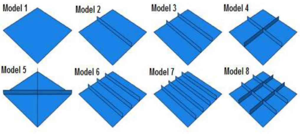
The dimensions of all the numerical examples were 1200×1200 mm2 with 16 mm thick. Rectangular stiffeners with dimension 20 mm thick and 80 mm height were used. The eight stiffener configura-tions which used in the numerical studies have shown in Figure 1.
Figure 1 Stiffener configurations.
2.2 Material Property
Latin American Journal of Solids and Structures 11(2014) 185 – 199
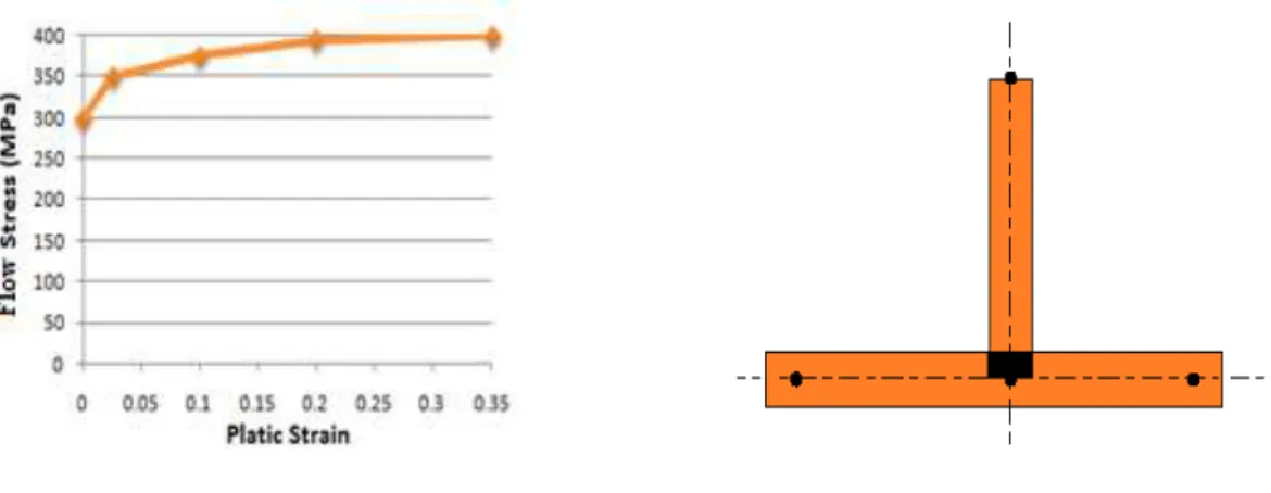
points to simulate the actual material behavior. Any number of points can be used. In this study multi-linear curve were used as shown in Figure 2. The material will behave as a linear elastic ma-terial up to the yield stress of the mama-terial. After this stage, it goes into the strain hardening stage until reaching the ultimate stress.
Plates and the stiffeners are joined directly at their mid-surfaces; therefore an area of material overlap will occur, as shown in Figure 3. This overlapping material and the extra stiffness creates by it would have little effect on the response because the thicknesses of the plates and stiffeners are small in comparison to other dimensions. Therefore, the effect of material overlapping was neglected in this study (Simulia, 2010).
Figure 2 – Plastic property. Figure 3 – Overlapping material.
Most of the metallic materials such as constructional steel show an increase in the yield stress with increasing strain rate. In the case of blast or explosion, the rate of loading is high; therefore strain-rate dependency is likely to be important. Strain-rate effects are included by adjusting the material dynamic yield stress at each Gauss point according to Eq. 1. R is the ratio of the dynamic yield stress to the static yield stress and D and n are experimentally defined material constants. Eq. 1 can rearrange to form new equation, Eq. 2, recognized as Cowper-Symonds relation (Jones, 1989). On the basis of this relation, it is obvious the yield stress depends on the deformation speed.
ε
.=
D
(
R
−
1)
n (1)σ
y
=
σ
01
+
ε
.D
1
n
⎡
⎣
⎢
⎢
⎢
⎤
⎦
⎥
⎥
⎥
(2)Latin American Journal of Solids and Structures 11(2014) 185 – 199
3 BLAST LOADING
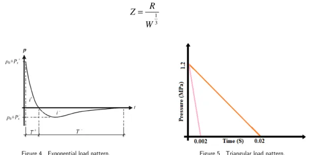
Figure 4 shows a typical blast pressure profile. The pressure time-history is divided into a positive and a negative phase. In the positive phase, maximum overpressure, Ps+, is developed instantane-ously and decays to atmospheric pressure, P0, in the time T+. For the negative phase, the maxi-mum negative pressure, Ps−, has much lower amplitude than the positive overpressure. The dura-tion of the negative phase, T−, is longer compared to the positive duration. The pressure time-history in Figure 4 can be approximated by the exponential Equation (3). The positive phase is more relevant in studies of blast effects on structures because of its high amplitude of the overpres-sure and bigger area under the positive phase of the presoverpres-sure–time curve (Ngo, et al., 2007). Then Eq. 3 is often simplified by a linearly decaying pressure-time history (Eq. 4) represent the triangular load pattern shown in Figure 5.
P
(
t
)
=
P
s+(1
−
t
T
+)
e
−bt
T+ (3)
P
(
t
)
=
P
max(1
−
t
T
d
)
(4)In these equation, P(t) is the overpressure at time t, Pmax and Ps+ are maximum over pressure in triangular and exponential loading pattern respectively and b is a experimental constant. Air blast loading can be qualified based on the charge weight and stand-off distance. The amount of charge of explosive in terms of weight is converted to an equivalent value of TNT weight by a con-version factor. That means TNT is employed as a reference for other explosives. Estimations of peak overpressure due to spherical blast based on the scaled distance. All equations use scaled dis-tance (Z) for calculating the parameters, which is derived by Eq. (5):
Z
=
R
W
1 3
(5)
Latin American Journal of Solids and Structures 11(2014) 185 – 199
Where R is the distance from the centre of the explosive source in meters, and W is the charge mass of equivalent TNT in kilograms. In this study, triangular load pattern was used. The loading function shown in Figure 5 is scaled such that Pmax= 1.2 MPa and time duration, td= 2 ms and td=20 ms, as shown in Figure 5. Different time duration was used to study the influence of time interval on dynamic response of plates.
4 VERIFICATION OF THE MODEL
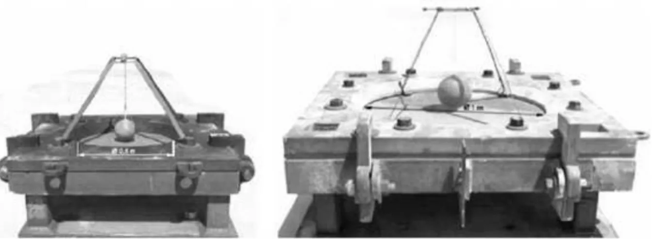
A circular plate subject to blast loading as a result of blast of 50 kg of TNT, 0.5 m directly above the center of the plate, was built up by Neuberger et al. (2007), as shown in Figure 6. In this part, this blast loaded plate numerically investigated in order to verify the model structures.
The plate has a radius of 1 m and a thickness of 0.05 m. One-quarter of the plate is modeled us-ing shell elements (See Figure 7). Blast loadus-ing is applied on the top surface of the plate. The densi-ty of the plate material is 7850 kg/m3, Young's modulus is 210 GPa and Poisson's ratio is 0.28. The plastic property is modeled with an isotropic hardening bilinear model, with yield stress of 1000 MPa. A nonlinear dynamic analysis is performed for a period of 4 milliseconds. The plate was sup-ported by two thick armor steel plates with circular holes that were tightened together with bolts and clamps. The thick plate that faces the charge has a hole with inclined side walls to prevent reflection of the blast wave to the tested plate. The measurement of the maximum dynamic deflec-tion of the plate was achieved by means of a specially devised comb-like device. The spherical TNT charges were hanged in air using fisherman’s net and were ignited from the center of the charge (Neuberger, et al., 2007).
Figure 6 Experimental setup at 2 different scales (S= 4, left, and S =2, right) (Neuberger et al., 2007).
Latin American Journal of Solids and Structures 11(2014) 185 – 199 Figure 7 Mises contours of one-quarter model of plate.
Figure 8 Time-History of midpoint displacement. Figure 9 Time-History of Mises Stress.
5 MESH DEPENDENCY
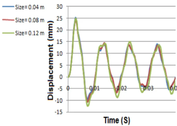
It is well known that the explicit analysis for blast loading depends on mesh configuration. On the other hand, the mesh size is also limited by the computer capacity and the dimensions of the model structure. One of the major features in the numerical simulation of blast loads is the use of an ade-quate mesh size.
Latin American Journal of Solids and Structures 11(2014) 185 – 199
Figure 10 – Influence of meshing on model 1 (td= 2 ms). Figure 11 – Influence of meshing on model 1 (td= 20 ms).
Figure 12 – Influence of meshing on model 2 (td= 20 ms). Figure 13 – Influence of meshing on model 3 (td= 20 ms).
6 RESULTS AND DISSCUSION
Nonlinear dynamic analysis is performed using the general purpose finite element package Abaqus/Explicit version 6.10. Unless otherwise specified, all comparisons are made with reference to the fully fixed boundary condition, rate-independent material and fine mesh.
6.1 Modal analysis
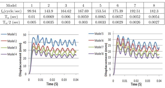
Latin American Journal of Solids and Structures 11(2014) 185 – 199 Table 1 Fundamental frequencies and periods.
Model 1 2 3 4 5 6 7 8
fn(cycle/sec) 99.94 143.9 164.62 167.69 153.54 175.39 192.51 182.3 Tn (sec) 0.01 0.0069 0.006 0.0059 0.0065 0.0057 0.0052 0.0054 Tn/2 (sec) 0.005 0.0035 0.003 0.003 0.0033 0.0029 0.0026 0.0027
Figure 14 Influence of stiffener configuration for model 1-4 (td= 20 ms).
Figure 15 Influence of stiffener configuration for model 5-8 (td= 20 ms).
6.2 Effect of stiffeners configuration
The results have shown that with the addition of more stiffeners, the maximum displacement de-creases. The configurations of stiffeners can have an important influence on the response of the stiff-ened plates. The maximum midpoint displacements for all models are shown in Table 2.
Table 2 Maximum midpoint displacement for different time intervals.
Maximum displacement
(mm)
Model
1 Model 2 Model 3 Model 4 Model 5 Model 6 Model 7
Model 8
Td=20 (msec) 49.23 38.97 35.02 30.92 33.78 31.14 27.53 25.32
Td=2 (msec) 25.2 16.68 14.23 11.91 10.79 12.2 10.81 8.65
Latin American Journal of Solids and Structures 11(2014) 185 – 199 Figure 16 Influence of stiffener configuration for model 1-4
(td= 2 ms).
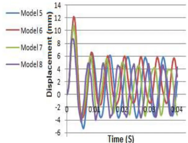
Figure 17 Influence of stiffener configuration for model 5-8 (td= 2 ms).
Figure 18 Influence of stiffener arrangement for model 3 and model 4.
Figure 19 Influence of stiffener arrangement for model 7 and model 8.
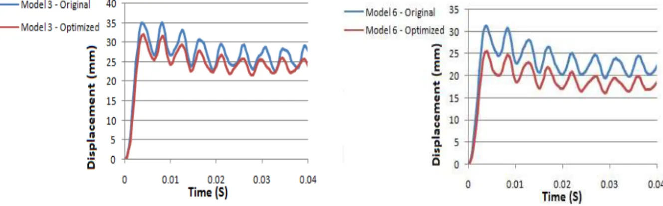
Results have shown that, if the main design purpose is to reduce the displacement, uniform dis-tribution of stiffener is not good method for installing stiffeners on plates. A more effective way for installation of stiffeners is shown in Figure 20. These models have same number of stiffener and also have same weight as original models, but stiffener concentrated in middle strip of plates, as close as possible to the axis of the plates. According to results midpoint displacement of optimized models meaningfully decreased as shown in Figure 21 and Figure 22.
Latin American Journal of Solids and Structures 11(2014) 185 – 199 Figure 21 Influence of optimization on model 3
(td= 20 ms).
Figure 22 Influence of optimization on model 6 (td= 20 ms).
6.3 Effect of boundary condition
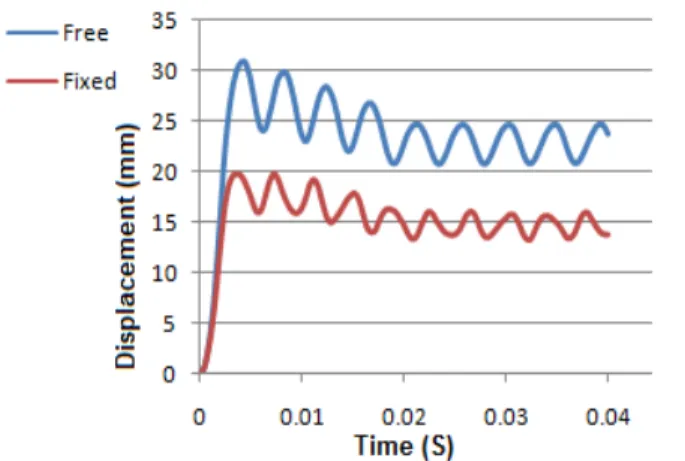
In this study the following 3 states of boundary conditions were adopted for plates; perfectly fixed, three edges fixed and two edges fixed. In the former, the fixed edges are parallel. These boundary conditions applied to plates. The main conclusions of this study are that the boundary conditions of plate have a significant influence on the dynamic response under blast loading. Freedom of one or more edges increases midpoint displacement drastically, as shown in Figure 23 and Figure 24. For study the effect of boundary condition of stiffeners on dynamic response of stiffened plates, two states of boundary conditions for stiffeners were adopted; free and perfectly fixed (with perfect-ly fixed plates). According to results, in plates with fixed stiffeners, midpoint displacement de-creased. As expected, with increasing in stiffener's number, influence of stiffener's boundary condi-tions is intensified. Figure 25 and Figure 26 have shown influence of stiffener's boundary condition for model 4 and model 8, respectively. Boundary conditions of stiffeners also have significant influ-ence on stress distribution in models. Figure 27 and Figure 28 show different patterns of Mises stress distribution in model 4, with free and fixed boundary conditions of stiffeners.
Figure 23 Influence of boundary conditions for model 4 (td= 20 ms).
Latin American Journal of Solids and Structures 11(2014) 185 – 199 Figure 25 Influence of boundary conditions of stiffeners for model
4 (td= 20 ms).
Figure 26 Influence of boundary conditions of stiffeners for model 8 (td= 20 ms).
Figure 27 Stress distribution (edges of stiffeners are free). Figure 28 Stress distribution (edges of stiffeners are fixed).
6.4 Effect of strain rate
Latin American Journal of Solids and Structures 11(2014) 185 – 199 Figure 29 Influence of strain rate on model 2
(td= 20ms).
Figure 30 Influence of strain rate on model 4 (td=2 ms).
6.5 Energy of models
The results were further confirmed by the observation of the time history of the energy of models. According to results, when the plates are at their maximum displacements, they have maximum strain energy. In this state, kinetic energy is at minimum. Figure 31 and Figure 32 represented time history of kinetic and strain energy for model 2 for different time interval.
Figure 31 History of energy for model 2 (td= 20ms).
Figure 32 History of energy for model 2 (td= 2ms).
Latin American Journal of Solids and Structures 11(2014) 185 – 199
Models 2, 3 and 7 have one, two and four stiffeners respectively, as shown in Figure 33, with the addition of more stiffeners, plastic energy meaningfully decreased, indicating a stiffer response and less midpoint displacement.
By the observation of the time history of the plastic energy in the models that strain rate is in-cluded, it is obvious that the plastic strain energy with strain-rate is reduced compared to the case without rate, indicating a stiffer response as shown in Figure 34.
Figure 33 History of plastic energy for different stiffener config-urations (td= 20ms).
Figure 34 Influence of strain rate on plastic energy (Model 2, td= 20ms).
7 CONCLUSIONS
In this paper the nonlinear dynamic response of square steel stiffened plates subjected to uniform blast loading was studied. Stiffener configurations, boundary conditions, fixing details, mesh de-pendency and strain rate, which maybe affect the dynamic response of the plates subjected to blast loading was considered. The results of this study can be summarized as follow:
• The ratio of the duration of the blast loading over the natural period of the stiffened plates, determined the development of maximum response either in force vibration phase or in the free vibration phase.
• Presence and configurations of stiffeners is very important, since it can affect the overall re-sponse of the plates. Arrangement of stiffeners can be important; in models with same number of stiffeners, intersected stiffeners represent less midpoint displacement than models with par-allel stiffeners.
• Results have shown that uniform distribution of stiffener isn’t good method for installing stiff-eners on plates under blast loading. It is more advantageous to put more stiffstiff-eners close to the center than at an even spacing.
• In unstiffened plate different meshes yield the same displacement, but refining the mesh leads to changes in the response of stiffened plates, because using only one first order element through the depth of the stiffener is not sufficient to model the response of plate accurately. • Boundary conditions of plates have a significant influence on the dynamic response of plates
dis-Latin American Journal of Solids and Structures 11(2014) 185 – 199 placement drastically. Boundary conditions of stiffeners also affect the dynamic response of plates and stress distribution under blast loading, especially in models with many stiffeners. Distribution of stress in plates mainly influenced by boundary conditions and stiffeners config-urations.
• When rate dependence is included, the midpoint displacement decreases meaningfully, there-fore the effects of strain rate should be incorporated in FEA solutions of blast loaded plates. However, the rate of decrease depends on the duration of blast loading and results are sensi-tive to the values of adopted material data.
References
Boh, J. W, Louca, L. A. and Choo, Y. S. (2004), "Strain rate effects on the response of stainless steel corrugated firewalls subjected to hydrocarbon explosions", J. Constr. Steel. Res., 60(1), 1–29.
Bonorchis, D. and Nurick, G. N. (2010), "The analysis and simulation of welded stiffener plates subjected to lo-calised blast loading", Int. J. Impact. Eng., 37, 260–273.
Chopra, A. K. (2001), Dynamics of structures: theory and application to earthquake engineering, Prentice Hall Inc., New Jersey, USA.
Hamedani, S. J., Khedmat, M. R. and Azkat, S. (2012), "Vibration analysis of stiffened plates using Finite
Element Method", Latin American Journal of Solids and Structures, 9, 1-20.
Hsieh, M., Hung, J. And Chen, D. (2008), "Investigation on the blast resistance of a stiffened door structure", J. Mar. Sci. Tech., 16(2), 149-157.
Jacinto, A. C., Ambrosini, R. D. and Danesi R. F. (2001), "Experimental and computational analysis of plates under air blast loading", Int. J. Impact. Eng., 25(10), 927-947.
Jacob, N., Yuen, S., Nurick, G. N., Bonorchis, D., Desai, S. A. and Tait D. (2004), "Scaling aspects of quadran-gular plates subjected to localized blast loads-experiments and predictions", Int. J. Impact. Eng., 30(8-9), 1179-1208.
Jones, N. (1989), Structural impact, Cambridge University Press, Cambridge, UK.
Kadid, A. (2008), "Stiffened plates subjected to uniform blast loading", J. Civ. Eng. Manag., 14(3), 155-161.
Neuberger, A. Peles, S. and Rittel, D. (2007), "Scaling the response of circular plates subjected to large and close-range spherical explosions. Part I: Air-blast loading", International Journal of Impact Engineering 34, 859– 873.
Ngo, T., Mendis, P., Gupta, A., & Ramsay, J. (2007). Blast loading and blast effects on structures–an overview. Electronic Journal of Structural Engineering, 7, 76-91.
Nguyen T. P. and Tran, M. T. (2011). "Response of Vertical Wall Structures under Blast Loading by Dynamic Analysis", Procedia Engineering, 14, 3308–3316.
Norris, G.H., Hansen, R.J., Holly, M.J., Biggs, J.M., Namyet, S. and Minami, J.K., (1959), Structural design for dynamic loads, McGraw-Hill, New York, USA.
Oskouei, A. V. and Kiakojouri, F. (2012). "Steel Plates Subjected to Uniform Blast Loading", Applied Mechanics and Materials, 108, 35-40.