ABSTRACT: This paper describes a multi-disciplinary design and optimization framework tailored for the conceptual development of high-altitude solar-powered unmanned aerial vehicles. The aircraft baseline coniguration that the framework is able to handle is very similar to that of Zephyr, which is developed by the UK based company QinetiQ. The disciplines of aerodynamics, structures, stability, weight, and systems were considered and integrated into a modeFrontier® worklow, capable of providing a relatively simple sizing, but highly realistic airplane.
KEYWORDS: Airplane design, Solar energy, Multi-disciplinary design and optimization, Airplane stability and control.
Optimal Design of a High-Altitude
Solar-Powered Unmanned Airplane
Bento Silva de Mattos1, Ney Rafael Secco1, Eduardo Francisco Salles1
INTRODUCTION
he present work is concerned with the optimal design of unmanned high-altitude long-endurance (HALE) solar-powered airplanes. In order to accomplish this, a multi-disciplinary design framework was elaborated employing the modeFrontier® (ESTECO, 2011) commercial optimization package. A brief technical retrospective of the development on solar-driven aircrat is provided in this section as well as the reasoning to address the utilization of such kind of airplane.
he irst light of a solar-powered aircrat took place on November 4th, 1974, when the remotely controlled Sunrise I, designed by Robert J. Boucher of AstroFlight, Inc., lew ater a catapult launch (Noth, 2008). he light lasted 20 minutes at an altitude of around 100 m (Noth, 2008).
AeroVironment, Inc. was founded in 1971 by the ultra-light airplane innovator Paul MacCready. Following the AstroFlight’s airplane debut, AeroVironment undertook a more ambitious project to design a human-piloted, solar-powered aircrat. he irm initially based its design on the human-powered Gossamer Albatross II and scaled it down to three-quarters of its previous size for solar-powered lights. his was easier to accomplish because, in early 1980, the Gossamer Albatross aircrat had participated in a light research program at NASA Dryden Research Center. Some of the Albatross lights were performed employing a small electric motor. he scaled-down aircrat was designated Gossamer Penguin (Fig. 1). It had a 71-t wingspan compared to the 21.64-m (96-t) span of the Gossamer Albatross (MacCready et al., 1983). Penguin’s Empty Weight was just 31 kg, it had a low-power requirement and, therefore, it was an excellent test bed for testing of solar power systems (Noth, 2008).
1.Instituto Tecnológico de Aeronáutica – São José dos Campos/SP – Brazil
Author for correspondence: Bento Silva de Mattos | Instituto Tecnológico de Aeronáutica | Praça Marechal Eduardo Gomes, 50 – Vila das Acácias | CEP 12.228-900 São José dos Campos/SP – Brazil | Email: [email protected]
AstroFlight, Inc., of Venice, California, provided the power plant for the Gossamer Penguin, an Astro Cobalt 40 electric motor. h is engine was designed to run at between 10,000 and 15,000 rpm, but the 11-t diameter propeller of Penguin rotates between 120 and 130 rpm. h e speed reduction was achieved with a three-stage gearbox with two timing pulley stages providing a reduction ratio of 5/1 each and a i nal chain reduction stage delivering a 5.12/1 ratio. Robert Boucher, designer of the Sunrise II, worked as a key consultant for both aircrat and for the Solar Challenger. h e power source for the initial l ights of the Gossamer Penguin consisted of 25 nickel-cadmium batteries and panels of 3,640 solar cells delivering 541W. h e battery-powered l ights took place at Shat er Airport near Bakersi eld, California. Paul MacCready’s son, Marshall, was the test pilot. He was 13 years old and weighed approximately 80 lb (36 kg) at that time. h e main targets of the test l ights were the determination of required power to l y the airplane, the optimization of the airframe/propulsion system, and pilot training. Flights took place on April 7th, 1980, and a short solar-powered one on May 18th. However, the oi cial project pilot was Janice Brown, a Bakersi eld school teacher who weighed in at slightly less than 45 kg and was a charter pilot with commercial, instrument, and glider ratings. She checked out in the plane at Shat er and made about 40 solar-powered l ights. Wind direction, turbulence, convection, temperature and radiation at Shat er in mid-summer proved to be less than ideal for Gossamer Penguin because of crosswinds at takeof and decreased solar power
output due to higher ambient temperatures. Consequently, the project moved to Dryden in late July, although conditions there also were not ideal. Nevertheless, Janice i nished the testing, and on August 7th, 1980, she l ew a public demonstration at Dryden in which she was able to cover 3.14 km in 14 minutes and 21 seconds. h is was signii cant as the i rst sustained l ight of an aircrat relying solely on direct solar power rather than batteries. It provided the designers with practical experience for developing a more ei cient solar-powered aircrat , taking into account that the Gossamer Penguin was fragile and had limited controllability. h e Penguin l ew preferably in the morning, when usually wind is minimal and consequently the turbulence level is still low. On the other hand, at this part of the day, the angle of the sun was low, requiring a tilting solar panel to capture properly the solar radiation (Noth, 2008).
From the lessons learned with Gossamer Penguin, AeroVironment engineering staf designed Solar Challenger, a piloted, solar-powered aircrat that was capable of high-altitude and long-endurance l ights (Noth, 2008).
h e last big step in aircrat powered by solar energy is the i rst l ight of twin-engine Solar Impulse airplane on December 3rd, 2009 (Solar Impulse, 2013). Solar Impulse is a long-range solar powered plane project currently being undertaken at the École Polytechnique Fédérale in Lausanne, Switzerland. h e project is promoted by Bertrand Piccard, who piloted the i rst balloon that was able to circumnavigate the world nonstop. h is project is expected to repeat that milestone in aviation history by employing a solar-powered airplane. h e i rst aircrat , oi cially named HB-SIA, is able to accommodate a single pilot, capable of taking of under its own power, and is intended to remain airborne up to 36 hours. Building on the experience of this prototype, a slightly larger follow-on design (HB-SIB) is planned to make circumnavigation of the globe in 20-25 days. On April 7th, 2010, the HB-SIA underwent an extended 87 minutes test l ight (Fig. 2). In contrast to earlier tests, the April l ight reached an altitude of 1,200 m (3,937 t ). In February 2012, Solar Impulse pilot Andre Borschberg spent more than 60 hours straight at the controls of the Solar Impulse l ight simulator (Fig. 3). Granted, he was able to get some sleep, sometimes napping for a whole 20 minutes at a time (Solar Impulse, 2013). At that time, Borschberg was approaching the end of a 72-hour stint in the simulator, running through a series of tests and challenges to prepare for what lies ahead
when he attempts to l y around the world in a solar airplane in 2014 (Solar Impulse, 2013).
In recent years, European countries are taking a more central role in the development of High Altitude/Long Endurance solar-powered unmanned aerial vehicles (UAVs). Several projects are either ongoing or being planned for advanced solar powered vehicles. In the 2000–2003 period, a team from the Politecnico de Torino, in Italy, together with a team from the University of York in the UK, developed a concept for the Heliplat – a Very-Long Endurance Solar Powered Autonomous Aircrat (VESPAA) (Romeo and Frulla, 2004). Heliplat and other VESPAA UAVs could play the role of a “pseudo satellite”, with the advantages of being closer to the ground, more l exible and at a cost lesser than an actual satellite. Heliplat-like HALE l ying above a major city will be able to cover a circular area of 1,000 km diameter, and process a predicted 425,000 cell phone conversations
simultaneously (Romeo and Frulla, 2004). h is means a user community of 8.5 million per unit (although this does not take into account data transmission).
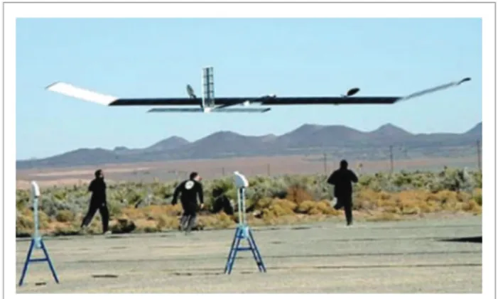
h e UAV platform of major interest to the present work is one that is capable to reach stratospheric altitudes and long endurance l ights (HALE category) and powered by solar energy. In this context, the Zephyr, developed by the UK based QinetiQ (QinetiQ, 2013), is a coni guration that is very similar to that envisaged by the authors. h e airplane carries a small payload and has no need for sophisticated assisted takeof systems or prepared airi elds (Fig. 4). h e Zephyr is a lightweight airplane
Figure 4. QinetiQ’s Zephyr during an assisted take off run (Photo: QinetiQ, 2013).
that uses a combination of a solar array and batteries to stay airborne. h e plane weighs just 31 kg and has a wingspan of about 18 m (QinetiQ, 2013). h e vehicle can circle over a particular area for extended periods. h e military uses the vehicle for reconnaissance and communications platforms. Civilian and scientii c programs use it for Earth observation. During the day, Zephyr uses its state-of-the-art solar cells spread across its wings to recharge high-power lithium-sulphur batteries and drive two propellers. At night, the energy stored in the batteries is sui cient to keep Zephyr airborne. h e batteries are supplied by Sion. In 2008, the airplane registered a recorded l ight, staying airborne for a total of 82 hours and 37 minutes, which is a very impressive number for a solar powered air vehicle (QinetiQ, 2013). h e Zephyr went for two straight nights without stopping for recharging and only relying on its solar powered batteries. h e airplane is able to climb to altitudes up to 18 km (58,000 t ) (QinetiQ, 2013).
Figure 2. Solar Impulse l ight on April 7th, 2010.
Missions conceived for Zephyr include forest and ocean monitoring, surveillance, and communication relay. Some highlights of Zephyr coni guration:
• Zephyr’s low-weight structure allows it to travel non-stop over long distances or to remain airborne in a desired station for a considerable long time.
• h e unique propeller design provides the aircrat with a higher power-to-weight ratio.
• h e aircrat l ies day and night powered by solar energy – recharging its batteries along the day.
• No complex launching mechanisms – the aircrat is launched manually by a ground crew of three people.
• Silent l ight – neither noise nor pollutant emissions.
• h e wing design takes into account thermal air currents to lit the aircrat to higher altitudes.
METHODOLOGY
Before starting with the design of any solar-powered aerial vehicle, it is important to establish how the solar energy will be converted into vehicle motion (propulsion) and how to provide power for the airplane systems. Usually, the wing is an appropriate place to be covered with solar cells, which collect solar radiation and transform it into electrical energy. Batteries, propulsion and systems operate under dif erent conditions and thus a converter package is necessary. An appliance called Maximum Power Point Tracking (MPPT) enables the extraction of maximum power of solar cells and supplies the aircrat systems. During night, there is considerably less energy from solar cells and battery shall fuli ll all power needs. Some modern solar cells are able to convert the infrared night radiation into electric power, enabling the batteries continuously to be loaded. h is kind of solar cell was not considered in the present work. Figure 5 provides a scheme of the energy management inside the aircrat .
SOLAR IRRADIATION MODELS
For a better understanding of the power system, it is necessary to describe the solar radiation model and the systems responsible for its transformation into useful energy.
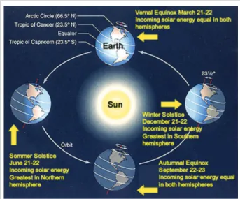
In order to proceed with the calculation of the solar panel area required on the airplane, it is necessary to estimate the available solar radiation in a given location and date. For this, the relative movement of the Earth around the Sun and of our planet around its axis must be well understood.
h e Earth has an elliptical orbit around the Sun, with an average distance of 150 million km. Period of revolution is of 365 days and 4 hours. On January 1st, the nearest distance between our planet and the Sun takes place (perihelion); and on July 1st, the remotest position, the distance is 3.3% farther than that of the closest position (aphelion). Considering that the incident solar radiation is inversely proportional to the square of the distance, the perihelion receives around 7% more radiation than when the Earth is at the aphelion. Another four points also are very important in the astronomy: the autumn and spring equinoxes; and summer and winter solstices (Fig. 6).
Solar Panels Engines, electronicequipament, others Converter
Batteries Night
Day
Figure 5. Solar energy conversion system to power engine and other aircraft systems.
h e perihelion and the aphelion are the days of most and least intense radiation, respectively. h e summer and winter solstices are the days with the longest and shortest time of solar radiation exposure. Being conservative, it is considered that the aircrat should able to l y in any condition and so the point of project is the critical day of the year, in which it receives the least radiation along the day.
h e solar irradiance models found in the literature are based on data collected in the Northern hemisphere, mainly in the United States and Europe. For the present work, the model R.SUN was employed (IET, 2013). h is sophisticated model was distributed by the Photovoltaic Geographical Information System (PVGIS) of the European Union. PVGIS provides online interactive maps of photovoltaic potentials in Europe and Africa. Figure 7 shows such a map considering the yearly sum of solar electricity generated by 1 kWp system with optimally-inclined modules. R.SUN was developed for the European and Africa environment and it is able to predict the direct and dif use irradiation and that rel ected by the Earth’s surface. h is last part of the solar irradiation is not taken into account in the present work, since the solar panels are located on the wing upper side of our solar-powered UAV.
the irradiation model. h e power demand should be easily achieved in the inter-tropical region, where Brazil is located, since the incident radiation is larger there.
ELECTRICAL LOAD
In the preceding paragraphs, the available power from solar irradiation was outlined. In this section, the concern is with the electrical power demand for the aircrat .
Power required for the payload package can vary. For this reason, an electrical demand of 100 and 200 W was considered. Power required for the control systems actuators is estimated to be 25.5 W. h e engine power can be modeled in the following way (Eq. 1; Anderson, 1989):
1 .5
√
P =CD CL
(mg)3 S ρ
2
(1)
QinetiQ’s Zephyr presents an estimated electrical load of 174 W. h is i gure occurs close to the stall condition, being necessary to adopt a safety margin. h ere are some power losses in the power plant system that increase the required power to operate the airplane. Such losses are caused by the propeller, the control box, the engine, and the gearbox, which present ei ciencies of 87, 95, 95, and 95%, respectively (Noth, 2008; Roskam, 2000). Taking into account such losses, the required weight-to-power ratio tops 100 kg/hp. h us, the cruise is not the most critical condition to dei ne the required power. Some critical maneuvers must be addressed for such purpose. h e airplane must be able to handle gusts and other severe operating conditions. However, in the present work, the used approach was based on similar weight-to-power ratios at cruise
Figure 8. Yearly variation of accumulated daily radiation. 14000
12000 10000
8000 6000
4000
A
cc
um
u
la
te
d E
ne
rg
y (W
h/m
2)
1 /Jan 0 2 0 0 0
1 4 /Mar 2 6 /May 7 /Aug 1 9 /Oct 3 1 /Dec
R.SUN is able to estimate the solar irradiation according to latitude, altitude, date and time of the day. In this way, it can be computed the radiation accumulated during an unclouded day. From this estimation, an example of density of energy per area is shown in Fig. 8.
According to the R.SUN model, for an aircrat at 40ºN latitude and l ying 16 km above sea level, the critical day is December 21st. In this day, the distribution of radiation is shown in Fig. 6. h e chosen latitude is the reference for
of some solar-powered planes (Table 1). h e adopted value was slightly higher than that one of Zephyr: 25 kg/hp.
Typical cruise power for electrical driven airplanes is 56% of the engine nominal power. h us, for the Zephyr airplane, this represents an increase of 140% and the adopted i gure for the present work airplane was of 17.9 kg/hp.
ACTUATORS
Actuators are employed in control surfaces like ailerons, rudder, and elevators. h e airplane under development is coni gured with no high-lit devices and presents no landing gear. German company Volz is the actuator supplier for the Zephyr UAV (Volz Servos, 2013). h e temperature of operation for usual actuator varies from 30 to 70ºC. However, in the tropopause, the typical temperature is -56.5ºC. For this reason, they developed a special actuator
able to withstand temperatures below -70ºC – model DA 13-05-EXP 11859 (Fig. 9).
All actuators of the DA-13-05 Volz family have the same size (37.4x34.9x13.3 mm), operating voltage (4.8 to 5 V), angle (130°), and casing mass (19 g) but they dif er by available output torque, device rotating speed and electrical current (power) (Volz Servos, 2013). Zephyr’s actuator is the most advanced available on market in its class. However, there is no public data available and therefore we adopted the specii cation of the DA 13-05-60 device.
SOLAR PANELS AND BATTERIES
h e solar panels are extremely important components, considering that they are the unique source of energy, except the charged batteries in the i rst day of operation. h e impact of solar panels on the project is unquestionable. h eir development was recorded to be slow and always has been a critical bottleneck for this kind of airplane. For example, Pathi nder and Pathi nder Plus were developed with the same characteristics, at the same time and using the same technology, and by the same team. However, they dif er in service ceiling, which is about 30,000 t for the Plus version thanks to increased ei ciency of solar panels.
Several characteristics of state-of-art solar panels were compared, among them the ei ciency and weight per area. Flexible panels (Fig. 10) were then selected. Both specii c weights are very similar and they can be considered as ultra-light panels. Ei ciency is the factor that was taken into account for panel selection as well. In a conservative way, in this study we consider ISA+15 atmosphere conditions, as the ei ciency increases with decreasing temperature. As result, the panel
Table 1. Weight to nominal power ratio for some solar-powered airplanes (Noth, 2008).
Airplane Weight-to-power ratio (kg/hp)
Solar challenger 60.98
Pathi nder 29.53
Pathi nder plus 23.77
Centurion 27.46
Zephyr (estimated) 22.37
with Copper indium gallium selenide (CIGS) technology produced by Swiss company Flisom was selected, providing maximum eiciency of 18.8% (Flisom, 2013).
he most used batteries for portable equipment have lithium in their composition. However, a new generation of batteries based on chemical reaction between lithium and sulfur is available, but the concept is experimental stage. he advantages are weight and volume reduction for the same charge capacity. Lithium-sulfur batteries made by Sion Power are very advanced and some versions have speciic energy above 265 Wh/kg (Volz Servos, 2013), value that was adopted in the present study.
Sion Power lithium sulfur (Li-S) batteries were itted into the Zeyphr airplane in 2010. he batteries played a critical role in the QinetiQ Zephyr smashing the world record for the longest duration unmanned light. As a result of an intensive joint development efort between Sion Power and QinetiQ, the Zephyr light exceeded 336 hours (14 days) of continuous light, signiicantly surpassing the previous oicial record of 30 hours 24 minutes set by Northrop Grumman’s RQ-4A Global Hawk in March 2001 (Sion Power™
, 2013). he Zephyr’s world record light was completed on July 23, 2010, at the US Army’s Yuma Proving Grounds in Yuma, Arizona (Sion Power™
, 2013).
OPTIMIZATION FRAMEWORK
he simulations for the airplane design under consideration were carried out by using the commercial sotware package modeFrontier®
V4.3 (ESTECO, 2011). he optimization framework modeFRONTIER provides a multi-objective optimization and design environment and it easily enables the coupling of CAD/computer aided engineering (CAE) tools, inite element structural analysis and computational luid dynamics (CFD) sotware. It is developed by ESTECO SpA and provides an environment for product engineers and designers (ESTECO, 2011). ModeFRONTIER®
is a Graphical User Interface (GUI) driven sotware written in Java that wraps around the CAE tool, performing the optimization by modifying the value assigned to the input variables, and analyzing the outputs as they can be deined as objectives and/or constraints of the design problem.
In the present work, the airplane coniguration that was select for study is very similar to that of the monoplane Qinetiq Zephyr, i.e., featuring a rectangular wing with a conventional tail, which is connected to the wing by a boom. he two engines are located at the inner wing.
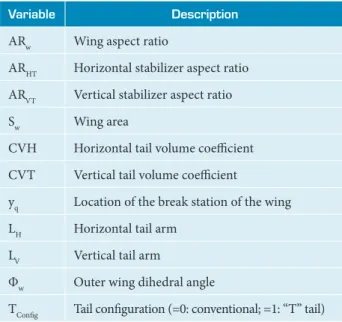
he design variables of the present optimization framework are given in Table 2. No geometric wing twist was considered. Two electrical power requirements related to two diferent payloads were simulated: 100 and 200 W.
Table 2. Design variables.
Variable Description
ARw Wing aspect ratio
ARHT Horizontal stabilizer aspect ratio
ARVT Vertical stabilizer aspect ratio
Sw Wing area
CVH Horizontal tail volume coeicient
CVT Vertical tail volume coeicient
yq Location of the break station of the wing
LH Horizontal tail arm
LV Vertical tail arm
Φw Outer wing dihedral angle
TConig Tail coniguration (=0: conventional; =1: “T” tail)
It is reasonable to assume that a lighter airplane will be cheaper. Airplane size is proportional to weight, and if there are two airplanes, one small and one large, with the same payload, the smaller one is structurally more eicient, considering it requires a lighter structure to perform the same mission. hus, airplane weight is an excellent indicator of coniguration eiciency and it was considered the objective to be minimized in the mono-objective simulations. he constraints that were taken into account are: handling qualities, rudder shadowing at stall condition of the horizontal tail, and the area of solar panels, which have to be smaller than the available area on the wing.
Multi-objective simulations were run as well. In this case, weight and energy surplus were taken as objectives and an electrical demand of 200 W for the payload was considered.
DISCIPLINES
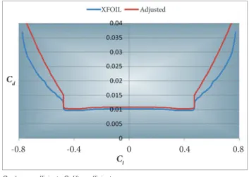
lies in the 150,000 – 200,000 range. Due to the low speed on station, high values of lit coei cient (Cl) are experienced by the airplane wing. Taken into account that energy supply is critical, a low-drag coni guration is mandatory. Based on Zephyr coni guration, a typical Cl of 0.83 at 17 km of altitude was estimated, considering a speed of 60 km/h. In this condition, almost 80% of span operates at Cl > 0.8, as shown in Fig. 11. h us, the biggest aerodynamic issue was to i nd out a low-drag airfoil for high local lit coei cients. Due to low Reynolds number, a laminar airfoil was considered, with “drag bucket” covering the desired Cl range (Fig. 12). h e NACA 6-digit family
to experimental results published by Abbott and Doenhof (Abbott and Doenhof , 1959) (Fig. 13). Table 3 contains some i gures obtained with XFOIL and from experimental data. h e correction for the polar curve was obtained by i tting a parabola to the non-laminar portion of the polar curve (Eq. 2):
Cd = Cd, XFOIL + 0.0006 (2)
Where Cd is the drag coei cient.
Figure 11. Lift coefi cient distribution along wingspan for a Zephyr-like airplane. Calculation performed with Athena Vortex Lattice (Sion Power™, 2013).
0.5 0.4 0.3 0.2 0.1 0 Cl
y/(b/2)
0 0.2 0.4 0.6 0.8 1
0.6 0.7 0.8 0.91
Figure 12. Typical drag polar of laminar airfoils. 0.0200
0.0180 0.0160 0.0140 0.0120 0.0100
Dr
ag C
o
effi
ci
e
n
t (
Cd
)
Lift coefficient (Cl)
-1.0 -0.5 0.0 0.5
0.0080 0.0060 0.0040 0.0020 0.0000
1.0 1.5
D R A G B U C K E T
N ACA 2415
NACA 66-415
of ers a variety of laminar airfoils and therefore the NACA 63412 proi le was selected to compose the wing. It combines all desired characteristics for the solar-powered UAV under consideration: high maximum lit coei cient (Clmax); moderate to low value for the moment coei cient (Cm); and 12% relative thickness, an adequate one. All the polar curves were computed with the panel code XFOIL (Drela, 2000) and adjusted to i t
Table 3. Abbott and XFOIL correlation.
Source Cd,laminar Cdm Clm k
Abbott 0.0051 0.0063 0.214 0.00732
XFOIL 0.0045 0.0061 0.177 0.00557
h e NACA 63010 airfoil was chosen for the horizontal and vertical tailplanes (Fig. 14). Aerodynamic calculations for the complete coni guration were performed with the incompressible Athena Vortex Lattice (AVL) vortex-lattice code (Youngren and Drela, 1988). AVL handles lit ing surfaces, fuselages, and booms. All required aerodynamic and stability derivative coei cients can be quickly calculated with AVL (Youngren and Drela, 1988).
Concerning load calculation, there is no applicable certii cation regulation for this kind of aircrat . Estimations that were carried out for the V-n diagram elaboration brought no realistic results. In this ef ort, FAA FAR-23 and JAR-VLA
Figure 13. Adjusted polar curve for NACA 63412 airfoil according to experimental data.
regulations were considered for a Zephyr-like airplane. For this reason, the present work considered a maximum a load factor of 3.8 for the structural sizing (Fig. 15).
analysis employed in the present study were very simple, as described by Megson (1999). h e bending moment is supported by stringers only and torsion loads, by both stringers and skin. h e structural layout is shown in Fig. 16, extending from leading edge to 25% of chord, where aerodynamic center is localized. h e thickness of the wing skin is the same along the entire span, but stringers may vary for each wing station.
h e cruise speed dei ned by the minimum required engine power for leveled and straight l ight. h e upper limit of the airplane dive speed was set to be 25% above the cruise speed. h e maximum load factor 3.8 was applied for wing sizing; horizontal and vertical tail stabilizers sizing considered the cruise condition, CLmax, and control surface del ection of 15º; and boom was sized considering simultaneous tails forces. Fuselage and engines were not calculated. h e methods of
Figure 16. Wing structural layout.
Ribs were not computed but it was assumed putting three of them per meter, with constant thickness.
h e boom has a cylindrical form with constant radius and thickness, approximated by thin-walled tube. It can easily withstand the existing loads for this kind of airplane. Its del ection was a constraint and used as sizing criteria. Carbon i ber was the standard material for solar airplanes, except skin, which is built of Mylar. Biaxially-oriented polyethylene terephthalate (BoPET) is a polyester i lm made from stretched polyethylene terephthalate (PET) and is used for its high tensile strength, chemical and dimensional stability, transparency, rel ectivity, gas and aroma barrier properties, and electrical insulation. A variety of companies manufacture BoPET and other polyester i lms under dif erent brand names. In the UK and the United States, the most well-known trade names are Mylar, Melinex and Hostaphan (Staugaitis and Kobren, 1996).
Densities of the selected materials for the airplane structure are well known and thus the calculation of the mass distribution is an easy task. h e fuselage and payload had i xed weight; the weight of batteries depends on the capacity to supply all systems during night; and engine weight was estimated based on methodology described by Noth (2008). h us, the weight and moment of inertia of each component can be estimated. h ese calculations are performed through an iterative process
Figure 14. Adjusted polar curve for NACA 63010 airfoil according to experimental data.
Cd: drag coefi cient; Cl: lift coefi cient.
14 12
-1
-2 nz
Equivalent Airspeed (m/s)
0 2 4 6 8 10
0 1 2 3 4
Maneuver
Gust
until convergence is reached according to some stopping rules. Demand for electric power depends strongly on the drag, which, in turn, depends on the lit coei cient.
Stability and control is a top issue in aircrat design, particularly hard for autonomous airplanes. Unplanned situations may happen and, in this case, there is no pilot to control and stabilize the airplane. Although an on-board computer can control an unstable airplane, this paves the way for accidents. For this reason, l ying qualities levels 1 or 2 were imposed, according to MIL-F8785C (Department of Defence of United States of America, 1980), adapted for UAVs (Peters and Andrisano, 1997). h is leads to the implementation of lateral-directional analyses in the design framework, addressing short-period, phugoid, roll, divergent spiral and Dutch-roll characteristics.
RESULTS
h e modeFrontier®
workl ow for the task under consideration is displayed in Fig. 17. h ere are ten design variables in total. h ey are related to the wing, horizontal tail (HT), and vertical tail (VT). h e AVL panel code was employed to calculate the aerodynamic coei cients and stability derivatives. Some MATLAB®
routines then evaluated the CLmax and dynamic behavior of the individuals that arise in the simulation process from data provided by AVL.
h e simulations were run on a desktop computer i tted with a single Intel Core2Quad Q6600 2.40 GHz processor, and 8.0 GB of installed Random Access Memory (RAM).
h e initial population was generated with the SOBOL algorithm, available in the modeFrontier® framework. SOBOL guarantees that any region of the design space does not become saturated, assuring that the entire domain be fuli lled with a great variety of individuals.
he multi-objective MOGA-II genetic algorithm (ESTECO, 2011) was chosen for running the simulations. MOGA-II is an ei cient multi-objective genetic algorithm that uses a smart multi-search elitism. h is new elitism operator is able to preserve some excellent solutions without bringing premature convergence to local-optimal frontiers. h e ei ciency of this algorithm has been orderly proved on six well known test functions for multi-objective optimization.
For simplicity, MOGA-II requires only very few user-provided parameters; several other parameters are internally settled in order to provide robustness and ei ciency to the optimizer. h e algorithm attempts a total number of evaluations that is equal to the number of points in the Design of Experiment (DOE) table (the initial population) multiplied by the number of generations.
MONO-OBJECTIVE SIMULATION
h e i rst runs revealed that a large number of individuals violated the posed restrictions. It is easy to understand, because in i rst generations genetic algorithm searches in all
Horizontal tail
Wing Vertical tail
Desgin variables
DOE MOGA II Geometry
Evaluate stabilizer combination (blanketing, etc...)
RestEmp AVL input AVL run
Loads AVL 1 Stabilizers
combination constraint
Loads
AVL 2
Extract AVL calculated parameters from output
file
Available area for
solar panels Required areafor solar
panels constraint
Energy susplus constraint Structural sizing Inertias
WeightminimizationWeight
Energy surplus Maximization
Energy surplus Stability
Flight quality
END Short period
Phugoid
Dutch roll
Roll
Divergent spiral
Short period level
Phugoid level
Dutch roll level
Roll level
Divergent spiral level
Flight quality constraints
SW
ΦW ARWyq ARHTLHCHT ARVTLVCVT
Table 4. Information for the standard demand simulation.
Variable Value
Generations 20
Number of individuals 400
Repeated individuals 41
Total processing time 7h51m25s
Average processing time for a single individual 1m19s
Average processing time for four individuals 5m15s considered domain and more advanced generations are next to optimum. So, algorithm naturally reduced the domain to small range that ofers good individuals, except mutations.
For the simulation tasks considering payload electrical demand of 100 W, 20 generations revealed to be enough to provide satisfactory convergence for obtaining an optimal airplane coniguration (Table 4). he irst runs recorded a large number of individuals that violated the prescribed constraints. Along the convergence process, the optimization framework naturally narrowed the band to generate individuals and most of them fulilled the imposed constraints (Fig. 18). In other hand, mutation may generate unfeasible individuals along the simulation process.
he area and weight are consistent with data from Zephyr, but its required power supply is unknown. However, the wing loading of the best individual is very close to that of Zephyr.
Considering only the best individuals that did not violate restrictions, it is possible to state that a minimum wing area of 16 m2 is required for obtaining a feasible coniguration. Larger areas can feed systems with greater capacity during the day and must be turned of at night because the battery does not have suicient storage capacity. For example, a system that requires 350 W can work under daylight conditions and must be turned of at night for airplanes with wing area set to 20 m2. he day chosen as the project point is very restrictive. If the same airplane lew in the summer, an 1,800 W of power could be generated during the day.
An overview of the best individual from the simulation is provided by Fig. 20. he optimal airplane presents 20 m2 of wing area and wing aspect ratio of 25 (Table 5). All handling qualities were level 1 on station.
50% 40% 30% 20% 10% 0%
Generation
1 2 3 4 5 6 7 8 9 10 11 12 13 14151617 1819 20
100% 90% 80% 70% 60%
Feasible Unfeasible Error
Figure 18. Feasible individual progression along the simulation process.
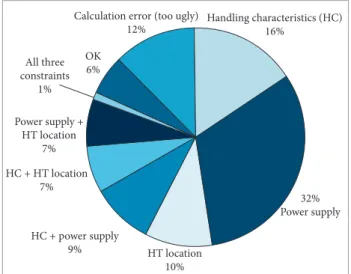
Handling characteristics (HC) 16%
Calculation error (too ugly) 12%
32% Power supply OK
6%
Power supply + HT location
7%
HC + HT location 7%
HC + power supply
9% HT location 10% All three
constraints 1%
Figure 19. Constraint violators pinpointing.
HT: horizontal tail; HC: handing characteristics.
he violation of power supply constraint is strongly associated with small wing area, while most of other violations are related to tail coniguration parameters. Figure 19 provides an overview of the constraint violation by individuals for the entire simulation.
6500 6100 5700 5300 4900 4500
P
o
w
er
(
W
)
Weight (kg)
30 50 70 90 110 130
4100 3700 3300 2900 2500
Figure 22. Feasible individuals from the multi-objective simulation.
5700
4700
3700
2700
P
owe
r
(
W
)
Weight (kg)
35 45 55 65 75
Figure 23. Pareto front of the multi-objective simulation.
Table 5. Optimal airplane from mono-objective simulation.
Sw 20 m
2 y
q 0.40
ARw 25 ARHT 2
Outer wing
dihedral angle 14° ARV 1.75
LV 4.25 m LH 4.75 m
Sw: wing area; Yq: break position; ARw: wing aspect ratio; ARHT: horizontal tail aspect ratio; ARv: vertical tail aspect ratio; Lv: vertical tail lever; LH: horizontal tail lever.
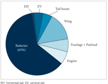
Airplane gross weight amounts 30.1 kg. h e weights of the airplane components are consistent and the battery weight fraction is huge (Fig. 21), revealing that this equipment presents an issue critical for the design of a solar-powered airplane. Typically, a battery generates 350 Wh/kg (265 Wh/kg considering the wrapper), but further development can increase this i gure to 600 Wh/kg, which would have great benei t for the coni guration of solar-powered aircrat .
As seen before, batteries are critical for design of solar powered airplanes. If the electrical power requirement for the payload is increased, the structural weight is also increased. h is directly af ects the weight of the engine and the required thrust to propel the airplane.
Multi-objective optimization
Weight minimization and power surplus maximization were taken as objectives for this task. Wing area was allowed to vary
between 30 and 60 m2. At er 40 generations with 30 individuals each, the simulation was stopped. Figure 22 shows the feasible individuals of the present simulation and Fig. 23, its Pareto front.
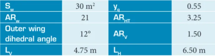
Here, the available power from the optimal individuals is considerably higher than that of the optimal airplane from the previous simulation. h is can be credited to the lower boundary that was set for the wing area, which was 50% higher than that of the optimal airplane from the mono-objective simulation. h e coni guration from the Pareto front with the lowest available power weighs just 35.21 kg, slightly over the weight of the optimal airplane from the previous simulation. Table 6 contains some characteristics of this airplane.
EV
EH
Tail boom
Wing
Fuselage + Payload
Engine
Batteries
(65%)
Figure 21. The above pie chart provides a weight breakdown of the optimal airplane.
Table 6. Characteristics of the optimal lowest power airplane from the multi-objective simulation.
Sw 30 m2 y
q 0.55
ARw 21 ARHT 3.25
Outer wing
dihedral angle 12° ARV 1.50
LV 4.75 m LH 6.50 m
Sw: wing area; Yq: break position; ARw: wing aspect ratio; ARHT: horizontal tail aspect ratio; ARv: vertical Tail aspect ratio; Lv: vertical tail lever; LH: horizontal
tail lever.
CONCLUDING REMARKS
he development of solar-powered airplanes in the past was directly afected by the technology of solar panels. Nowadays, alongside with the solar panel eiciency issue, energy storage became a major concern for the design of solar air vehicles. In addition, considering that there are few airplanes lying in altitudes from 15 to 18 km, there are also few aircrat systems manufacturers able to deliver products capable of working under severe environmental conditions like the ones found in such altitudes.
he application of optimization tools proved to be quite appropriate, as provided in less than one day running a very large variety of airplanes, for which one can identify the strengths, weaknesses, and typical values of the variables for a good design. he case study proposed is an excellent example of this, because there are few semi-empirical mathematical models and built aircrat data, and even then with the application of simple theories, it was possible to design and verify the consistency with the few existing models.
Future work will encompass the wing and tail airfoils as design variables.
ACKNOWLEDGMENTS
he authors thank Fundação de Amparo à Pesquisa do Estado de São Paulo (FAPESP) for its support by the project 2007/00305-5.
REFERENCES
Abbott, I.H. and Doenhoff, A.E., 1959, “Theory of wing sections”, Dover Publications, Mineola, NY, USA. 693 p.
Anderson, J.D., 1989, “Introduction to Flight,” 3rd Edition,
McGraw-Hill, USA.
Department of Defence of United States of America, 1980, “MIL-F-8785C: Military Speciication Flying Qualities of Piloted Airplanes”, Washington, DC.
Drela, M., 2000, “X-FOIL subsonic development system” [Internet], Massachusetts Institute of Technology (MIT).Available from: http://web. mit.edu/drela/Public/web/xfoil/. Accessed: June, 2006.
ESTECO s.p.a., modeFrontier® 4 User Manual, 2011.
Flisom – Flexible Solar Modules [Internet]. Available from: http://www. lisom.ch. Accessed: April 26, 2013.
Joint Research Centre, Institute for Energy and Transport (IET), “Solar Radiation and GIS” [Internet]. Available from: http://re.jrc.ec.europa.eu/ pvgis/solres/solmod3.htm. Accessed: April 26, 2013.
MacCready, P.B., Lissaman, P.B.S., Morgan, W.R., and Burke. J.D., 1983, “Sun-Powered Aircraft Designs”, Journal of Aircraft, Vol. 20, No 6, pp. 487-493.
Megson, T.H.G., 1999, “Aircraft structures for engineering students”, 3rd
Edition, Butterworth Scientiic, Oxford.
Noth, A., 2008, “Design of Solar Powered Airplanes for Continuous Flight,” Ph.D. Thesis, École Polytechnique Fédérale de Lausanne, Swiss.
Peters, M.E. and Andrisano, D., 1997, “The determination of longitudinal
lying qualities requirements for light weight unmanned aircraft,” AIAA Guidance, Navigation, and Control Conference, New Orleans, LA, Aug. 11-13.
QinetiQ [Internet]. Available from: http://www.qinetiq.com/. Accessed: April 26, 2013.
Romeo, G. and Frulla, G., 2004, “Heliplat: High Altitude Very-Long Endurance Solar Powered UAV for Telecommunication and Earth Observation Applications”, The Aeronautical Journal, Vol. 108, pp. 277-293.
Roskam, J., 2000, “Airplane Design, Part VI: Preliminary Calculation of Aerodynamics, Thrust and Power Characteristics”, The University of Kansas, Lawrence. DARcorporation.
Sion Power™ [Internet]. Available from: http://www.sionpower.com/. Accessed: April 26, 2013.
Solar Impulse [Internet]. Available from: http://www.solarimpulse.com/. Accessed; April 26, 2013.
Staugaitis, C. and Kobren, L., 1996, “Mechanical and Physical Properties of the Echo II Metal-Polymer Laminate,” NASA TN D-3409, NASA Goddard Space Flight Center.
Volz Servos [Internet]. Available from: http://www.volz-servos.com/en/ index.php?m=m. Accessed: April 26, 2013.