264 Brazilian Journal of Physics, vol. 38, no. 2, June, 2008
Study of Dense Plasma-Surface Interaction by a Filippov type Plasma Focus Device
M. Habibi1, R. Amrollahi1, and M. Farrahi2
1Amir Kabir University of Technology (Tehran Polytechnic) & RPRC, Tehran, Iran 2Atomic Energy Organization of Iran, Fusion Research Center, Tehran, Iran
Received on 5 March, 2008
In this paper we have tried to investigate of dense plasma-material interaction in a Filippov type plasma focus (90KJ, 25KV, 288µf) facility. Dense plasma focus discharges are known as a remarkable source of hot plasma bunches and fast streams, fast neutrons, hard and soft X-rays, and energetic particles such as ions and electrons. The Aluminum made targets with 20cm in diameter and thickness 5mm, were placed at the central part of plasma focus cathode. These targets were exposed to perpendicular dense high temperature plasma stream incidence. The working gases for these experiments were Argon, Deuterium +Krypton, Helium, and pure Deuterium. We took advantage of changeable targets surface and used SEM technique for analyzing irradiated samples by various working gases. As it shown from SEM pictures and surface profiles, melt layer erosion by melt motion, surface smoothing, and bubble formation were some of different effects caused by diverse working conditions.
Keywords: Plasma focus; Plasma-wall interaction; Bubbling effect; Melt layer motion; Surface smoothing
I. INTRODUCTION
The dense plasma focus (DPF) devices were developed in the early 1960s as a modification of the classical Z-pinch by J. W. Mather in the USA and N. V. Filippov in former soviet union. It is a device which produces an electrical discharge in a rarefied gas with current that can vary, according to the energy and working voltage, from a few kA to several MA. Studies of the DPF have shown that a plasma of density 1025 m−3and temperature 1keV can be achieved in a hot current carrying filament a few millimeters in diameter and about a centimeter in length. Plasma focus discharges are known as a remarkable source of hot plasma bunches and fast streams, fast neutrons proceeding from deuterium reactions, hard and soft X-rays, coming from different gases and the anodes in the discharge chamber, and energetic particles such as ions and electrons due to m=0 instabilities which may produce disrup-tions in plasma column for several nanoseconds. The spatial charge separation as well as the rapid change in the system inductance can generate strong electric fields that accelerate ions toward the top of the chamber and electrons toward the positively charged anode[1-5]. One of the main issues in the field of nuclear fusion research is the engineering design of structural materials. Since the plasma focus is a cost efficient and user friendly device, it allows one to simulate the plasma-material interaction studies of tokamaks and these studies are of importance for nuclear researches. In this study we have tried to investigate the behavior of plasma – Aluminium tar-get interaction in DENA plasma focus facility.
II. EXPERIMENTAL SET-UP
DENA is a Filippov type plasma focus facility, with a ca-pacitor bank of 288µF, a maximum supplied energy 90KJ(at Vmax=25KV) and giving a peak discharge current of about 2.8MA. Its anode is a disk of copper, with a diameter of 48cm, radius of 25cm, and a relatively easy changed anode inserts at it’s center. It is isolated from the cathode by a cylindrical
porcelain insulator with a height of 12cm, and a diameter of 48cm. Lateral wall of cathode is made of stainless steel. Up-per cover of the cathode is a disk of aluminium with a diameter of 75cm. There is an orifice in the center of this cover, with an aperture with a diameter of 20cm. This orifice is closed by a 5mm thick Aluminium target that has been placed in front of the anode surface at the distance of 12cm[6].Chamber volume is about 61000cm3. The DENA facility scheme, and a picture of this device are shown in Fig. 1.
III. EXPERIMENTS
Aluminium targets with 20cm in diameter and thickness 5mm, were placed at the central part of cathode(it shown in Fig.1). These targets were exposed to perpendicular dense high temperature plasma stream incidence. For all shots in-vestigated in this study, the device was operated at 16kV and the pressure varied from 0.8 to 1 torr. The working gases for these experiments were Argon with 100 shots, pure Deuterium with 100 shots, and Deuterium+%2 Krypton with 200 shots.
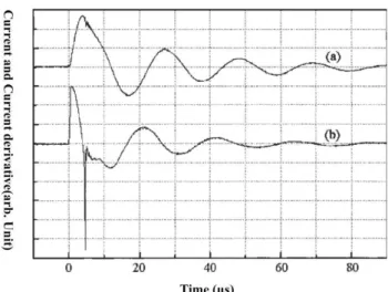
The discharge current and the current derivative were mea-sured by Rogowski coil and magnetic probe, respectively. Fig. 2 displays typical current derivative signal of DENA plasma focus. It is accepted that the negative peak of current derivative, corresponds to the minimum pinch diameter.
In Fig. 3 pin-hole Soft X-ray (SXR) images taken during discharges with Ar, D2, and D2+%2Kr are shown. These im-ages suggest the existence of a homogeneous plasma column that we need for reliable investigation.
We used scanning electron microscopy (SEM) techniques for analysing irradiated samples. Fig. 4 shows SEM images of Aluminium samples before and after plasma actions. In Fig. 5 images of Al targets are shown.
M. Habibi, R. Amrollahi, and M. Farrahi 265
FIG. 1: Scheme(left) and a picture(right) of the DENA facility : 1-discharge chamber; 2-anode; 3- insulator; 4-anode insert; 5-Aluminium target; 6-vacuum spark gap; 7-semiconductor detector; 8-neutron detector; 9-vacuum diode with NaI scientilator; 10-pin-hole camera; 11-plasma current sheath; 12-magnetic probe; 13-capacitor energy storage.
FIG. 2: Typical current (a) and current derivative (b) signals of the DENA plasma focus.
IV. EXPERIMENTAL RESULTS
As shown in Fig. 3, the observation over compression zone localization in space is attained with a pin-hole camera. Darker images can be cleary observed, which correspond to
266 Brazilian Journal of Physics, vol. 38, no. 2, June, 2008
(a) (b)
(c) (d)
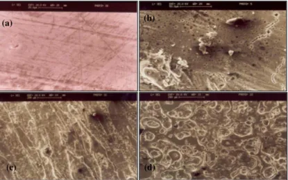
FIG. 4: SEM images of Aluminium samples. Before plasma exposure (a); after plasma exposure with Ar (b); D2+%2Kr (c); and D2(d).
(a)
(b)
(c)
Fig.5. images of aluminium targets after plasma axposure with (a) Ar; (b) D2+%2Kr; and
(c) D2
100µm
1mm
FIG.6: Al melt layer profile irradiated after 80 shots of Ar.
the higher intense irradiating streams. Inside the pinch col-umn, practically when admixtures of Deuterium and Krypton
are applied, miniature regions of high density and high tem-perature plasma are formed (Fig. 3.b). Experiments show that “hot spots” lead to enhanced neutron yield [7].
mo-M. Habibi, R. Amrollahi, and mo-M. Farrahi 267
tion. When the high voltage pulse is applied an azimuthal symmetric electrical discharge will be initiated and due to the J×B force the current is lifted off in an inverse pinch man-ner and plasma pressure gradient has it’s maximum value in the central part of target. The most pronouced melt motion is registered in the region of the maximum gradient of pres-sure [8]. Macroscopic motion of the melt layer and surface cracking are the main factors responsible for Aluminium tar-get erosion. Our experiments show that etching of aluminium surface is noticeable in the central part of target. It is difficult to determine an erosion crater because of the large roughness of the surface. As shown in Fig.6 the crater with a maximum depth of 200µm, and the diameter of about 8.5mm is observed close to the mountains. A considerable roughness is observed at these regions. The melt layer is subjected to external forces such as surface tension, gradients of plasma pressure and oth-ers. Melt motion driven by external forces produces signifi-cant macroscopic erosion of materials[5].
Surface smoothing was shown in Figs. 5.a and 5.b, using Ar and D2+%2Kr plasma ion beams. These cluster beams are able to deliver energy of plasma ions to a target and redirect their motion along the surface. This result in a smoothing of the surface as depressions are filled with material transported from surface protrusions [9].
Bubble expansion and bubble collapse are illustrated in
Figs. 4.c and 4.d, for example. When D2ions strike the first wall, they penetrate to a given depth and come to rest. If the irradiation dose is high enough, these atoms coalesce to form bubbles [10]. On the other hand, as shown in Fig. 4.c, adding Krypton admixture to the Deuterium working gas lead to col-lapsing bubbles and greater surface damage.
V. CONCLUSION
In this article the results of experimental investigation of melt layer macroscopic erosion, bubbling effect, and surface smoothing are presented, using Ar and D2+%2Kr as working gases, under irradiation the strong melting and droplet splash-ing with redeposition of splashed materials at the surfaces in the neighborhood of the melted area were clearly identified. The wavy structure at the surface of the melt layers and moun-tain formation were determined as a result of plasma pressure gradient by hot plasma bunches and powerfull radiation after and before current disruption in plasma focus. Irradiation of sample with D2and D2+%2Kr lead to bubble formation. Col-lapsing bubble in Fig. 4.c is due to adding Krypton admixture to the Deuterium working gas. Surface smoothing in Figs. 5.a and 5.b was illustrated using Ar and Kr gases.
[1] M. Zakaullah, Ijaz Akhtar, and G. Murtaza, Physics of Plasmas,
6, 3188 (1999).
[2] M. G. Haines, Dense plasma in Z pinches and the plasma focus, Philosophical Transactions of the Royal Society of London, se-ries A, 1981, No. 1456
[3] T. Oppenlanderet al, The plasma focus current in the compres-sion phase, Plasma Physics,19, 1977.
[4] M. J. Rhee, Appl. Phys. Lett.37, 906 (1980). [5] M. Sadiqet al, Physics Letters A352, 150 (2006).
[6] M. A. Tafreshiet al, Dena, a new PF Device, Nukleonica,46, S85 (2001).
[7] R. Antanasijeviet al, Radiation Measurements, 281-6, 241 (1997).
[8] V. I. Tershinet al,Journal of Nuclear Materials,313-316, 685 (2003).
[9] I. Yamada, A short review of ionized cluster beam technology, Nuclear Instruments and Methods in Physics Research Section B: Beam Interactions with Materials and Atoms,99, 1-4, 240 (1995).