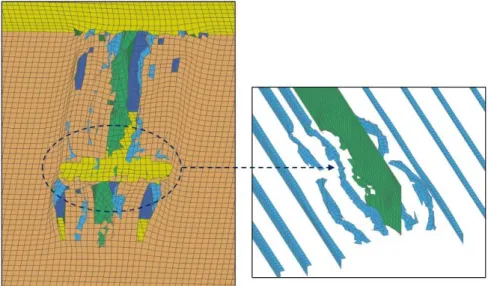
Abstract
Possibility of a water-transportation mode to experience numerous accidental loads is predicted limitless and always demand sustainable analysis. Impact phenomenon raises as main reason of environmental damage, for instance, grounding contributes in form of short-time impact and produces massive damage on the bottom structure of a marine vessels, e.g. ship. In this work, a series of numerical experi-ment is conducted with considering contribution of several parame-ters, namely impact location and seabed topology on the bottom structure of a tanker ship. The initial stage is conducted to obtain validation of the numerical method and configuration using impact test to ensure reliability of the present methodology which considers the finite element approach. In the second stage, proposed scenarios are calculated and overall evaluation of the damage extent is per-formed to observe resistance and behaviour of the bottom structure. Structural condition after grounding, rupture energy and crushing force are presented to observe history of grounding process. Contri-bution of the numerical parameter in form of meshing size is pre-sented to provide adequate consideration in both of physical and nu-merical parameters. Finally, tendency of the target structure is sum-marized to provide prediction of further behaviour during the bottom structure experiences grounding with various scenarios. An alterna-tive solution in respecting time cost is proposed and can be consid-ered for other impact simulation and analysis.
Keywords
Ship grounding, bottom structure, seabed topology, finite element (FE) method, structural behaviour
Structural Analysis of the Double Bottom Structure
During Ship Grounding by Finite Element Approach
1 INTRODUCTION
Most of impact phenomena in ocean engineering and marine structure harm ships as the main subject during its operation. Accidental loads on the side and bottom structures produce remarkable chain
Aditya Rio Prabowo a Bo Cao b
Dong Myung Bae c Sung Yong Bae c Ahmad Fauzan Zakki d Jung Min Sohn c
a Interdisciplinary Program of Marine
Convergence Design, Pukyong National University, South Korea
b China Shipbuilding Industry Corporation
Economic Research Center, China
c Department of NavalArchitecture and
Marine Systems Engineering, Pukyong National University, South Korea [jminz@pknu.ac.kr]
d Department of Naval Architecture,
Diponegoro University, Indonesia
http://dx.doi.org/10.1590/1679-78253648
reactions, for example damaged cargo, repair and evacuation costs, and in extreme cases, human life losses and environmental damages are found. Grounding and stranding become serious threat to the bottom structure of maritime vessel and environment as damage cost and water pollution are corre-lating each other during the event process, where failure of structural component is a result guarantee of the mentioned chain reactions. Serious attention has been paid to develop ship structure by intro-ducing the double hull structure especially for dangerous-valuable commodities carrier and passenger vessel. Despite of this progress, accident scenario in grounding and other impact phenomena, e.g. ice-structure interaction (Bae et al. 2016a) and ship collision (Prabowo et al. 2016a,b) can be considered almost limitless as various factor and parameter are involved, which make analysis and simulation are continuously conducted by related parties together with various scenarios. Parameter in impact is observed by respected parties in collaboration institutions of Indonesia-Korea (Bae et al. 2016b),
Poland (Wiśniewski and Kołakowski, 2003), and Demark (Simonsen, 1997a). Observation on damage
is performed to present fundamental data to estimate further casualties, such as amount of oil spill in grounding. Therefore, analyses of possible scenarios should be fulfilled, especially based on sailing routes. Different routes will give several predictions of damage contour as variety of seabed topologies and other physical parameters on the ship and numerical modelling can contribute to result of a scenario.
In the present work, analysis of grounding phenomenon is conducted by the numerical experiment. Impact test is taken as verification of the numerical setting and configuration. Impact location and seabed topology are considered as applied parameters, and contribution of these aspects to structural failure on the bottom structure is presented consecutively. A study in meshing size is presented in final section to provide further information related to numerical parameter for structural analysis.
2 REVIEWS ON IMPACT ENGINEERING AND ANALYSIS
Based on these reviews, it can be concluded that ship grounding has been studied for several parameters, including its mechanism, human error and damage distribution. These works are neces-sary to be conducted in order to improve knowledge of related parties for a nonlinear phenomenon, i.e. grounding. Human error aspect in ship grounding indeed leads to structural failure which endan-gers safety of passenger, crew, and cargo. Failure which is stated before, cannot be separated from damages mechanism and distribution. These parameters are certainly affected by topology character-istic during interaction between ship structure and seabed. In the pioneer studies for ship grounding, physical characteristic is focussed on ship structure with minimum information regarding specific physical data of indenter. This aspect is considered vital in the nonlinear analysis as it will contribute directly to damage contour and structural behaviour during and after grounding process, for instance deformed zone, rupture energy, etc. This work is addressed to provide estimation of grounding damage on ship structure using specific seabed characteristic. Topology parameter of seabed is taken into consideration for this work. Present seabed data can be used as adequate reference for further analysis in implementing indenter data to achieve reasonable prediction of ship grounding. Validation of the present numerical configuration is also conducted to ensure reliability of the calculation results.
3 BRIEF CONCEPT ON ALGORITHM AND COMPUTATIONAL INSTRUMENT
Implementation of the nonlinear analysis is considered to be the most suitable for the present study as ship grounding is a very complex process. It involves large contact forces, crushing structure com-ponents, rupture of shell plating, while interacting with global motions. The consequences may be remarkable and the process is highly nonlinear. In this research, a series of nonlinear dynamic analysis is conducted using the ANSYS LS-DYNA (ANSYS, 2013) to produce numerical experiment data. The algorithm is characterized as given in Equations 1 and 2.
1
int
t ext t
t
M
F
F
a
(1)
contact hg n TF
F
d
B
F
int
(2)where
a
t is the acceleration at time t,
M is the mass matrix,
F
text is the applied external and body force vector,
F
tint is the internal force vector given by Equation (2), hgF
is the hourglassresistance force, and contact
F
is the contact force.The model is progressing by adding the updated displacement variable {u} to the initial model {x0}, as presented in Equations 3 and 4.
x
tt
x
0
u
tt (3)where K is the contact stiffeness, xpenetr is the distance between two existing nodes on separate contact
bodies, λ is the Lagrange Multiplier.
The explicit solution strategy is considered efficient because the stiffness matrix does not need to be processed, and furthermore no iteration are performed. This analysis type is suitable to define large-scale deformation with high contact force, which involve structural rupture, strain, and model crushing. A series of grounding simulation in this work was conducted on a user defined computer of 8-cores 4th Generation Intel Core i7-4790 Processor, Base Frequency 3.6 GHz Max Frequency 4.00 GHz, 16 GB RAM, with running time between 500-630 min.
4 VALIDATION OF NUMERICAL CONFIGURATION USING IMPACT TEST
4.1 Finite Element Procedure
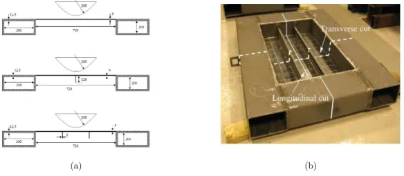
The validation was carried out based on experiment of Alsos and Amdahl (2009) at NTNU. The test is conducted by forcing a model of seabed, a so called indenter laterally into the plate. The involved objects in the experiment are restricted to contact between the indenter and one plate section. Con-figuration of this experiment is given in actual model and technical illustration in Figure 1. The target consists three components, namely plate, stiffener, and hollow frame which their properties are de-scribed in Table 1.
(a) (b)
Figure 1: Illustrations of impact test: (a) technical drawing, and (b) plate specimen (Alsos and Amdahl, 2009).
Material
type Component Material grade K (MPa) n εplate εf σY (MPa)
A Plate S235JR-EN10025 640 0.22 0.003 0.35 260
B Stiffener S235JR-EN10025 760 0.225 0.015 0.35 340
C Hollow frame S235JR-EN100210 830 0.18 0.01 0.28 390
During experiment, the indenter will penetrate the stiffened plate approximately until 0.25 m while the stiffened plate is supported by hollow frame. There are three models of the plate, such as regular plate, stiffened plate by one flat bar, and stiffened plate with 2 flat bar. The validation of present work will be performed in form of numerical experiment by ANSYS LS-DYNA (ANSYS, 2013). The engineering model of the plate is built and implemented by fully integrated (FI) Be-lytschko-Tsay shell element as element formulation. During analysis, the indenter moves to centre of the plate with constant velocity 0.6 m/s while the lower part of the plate model is constrained in translation and rotational directions. Illustration of the numerical experiment is presented in Figure 2. The mesh sizes 10 and 15 mm are chosen to be applied the numerical models. Calculation results of the numerical calculation will be compared with result of the impact test in terms of force and deformed zone. This discussion will be presented in next section.
(a) (b)
Figure 2: Preparation for numerical experiment of the present study: (a) upper view of the involved objects. The green entity represents the indenter and the blue plane denotes the target area. The hollow frame is presented in
dark grey. (b) constraints on the lower side of the plate. Arrows highlight location of boundary condition.
4.2 Results
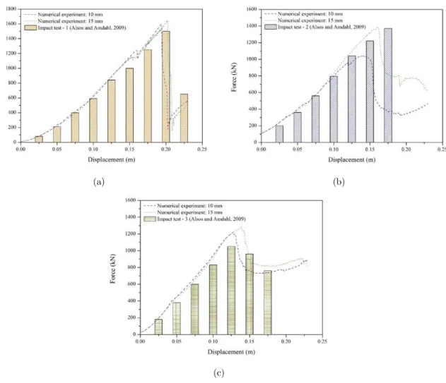
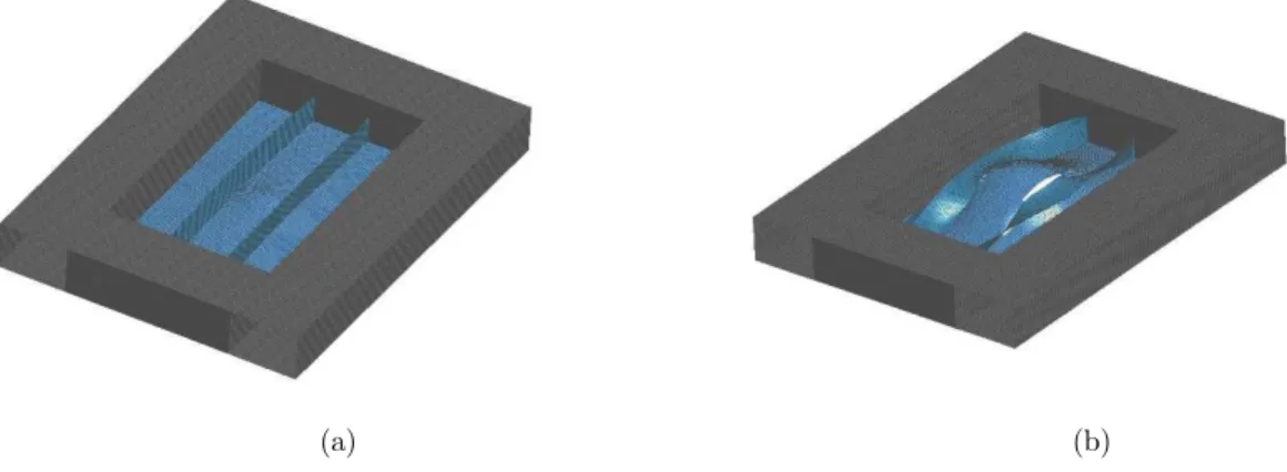
Firstly, results of numerical experiment are compared with the test in term of the force. Distinction in force history during penetration process between three results is presented in Figure 3. Secondly, deformation zone of the present configuration is evaluated using damage pattern of the impact test (Figures 4 and 5). Observation in force indicates that the present method produced good correlation with the actual experiment. Confirmation of deformation pattern in Figures 4 and 5 also shows good match for deformation contour before failure and tearing shape after failure. Even though different characteristic of the force is shown on plate with one stiffener 10 mm meshing size, overall benchmark study results are providing evidence of robustness and reliability of the present methodology on finite element simulation.
(a) (b)
(c)
Figure 3: Force characteristic in benchmark particulars: (a) regular plate, (b) one stiffener, and (c) two stiffeners.
(a) (b)
(a) (b)
Figure 5: Damage extent of the impact test – 3 by the present method: (a) before failure, and (b) after failure.
5 SHIP GROUNDING
5.1 Finite Element Model and Input Data
The target structure is built based on double bottom of a 17,000 t class chemical tanker which the main data is presented as follows: length 144 m, breadth 22.60 m, depth 12.50 m, draught 9.10 m. The scantling model and general arrangement of this ship are presented in Figures 6 and 7 consecu-tively.
(a) (a)
Figure 6: Experimental model: (a) overall component, and (b) intercostal on bottom construction.
The finite element model of the bottom structure is implemented by element-length-to-thickness (ELT) ratio with range 8-10 as mentioned in previous work of Haris and Amdahl (2013). This ratio makes the model consists 122,873 nodes and total element number is 127,056. Implementation of this ratio is used for analyses of location and seabed while in mesh observation, several ratios will be applied. Detail configuration of grounding scenario will be presented in next sub-section. Element formulation fully integrated Belytschko-Tsay is chosen and implemented into the model which in same time, deformable characteristic is applied. Even though it needs more time than ordinary Be-lytschko-Tsay, in a simulation process which involves high nonlinearities, it is very important to ensure undesired characteristic do not take place, e.g. hourglass. Based on this consideration, fully integrated version of the shell formulation is taken into simulation. Full-scale bottom structure is modelled and during grounding process, the displacement on the structure is set to be fixed on cen-treline with the fully fixation is applied on both ends. At the end of the inner bottom and bottom plating, axial displacements are restrained. Plastic-kinematic material (ANSYS, 2013) is given to the deformable bottom structure. The yield function of this material model is presented in Equations 5 and 6, and material properties for the structure is given in Table 2. The failure of ship structure in case of grounding can be defined as the tearing of the bottom plating and collapses of transverse and longitudinal members. It is known from numerous practical experiences and theoretical studies that the failure depends also on the stress states resulted under complicated loads in the structure. Influ-ence of manufacture defect which is highly influInflu-enced by production quality and process gives an additional factor that will affect rupture process. This process in finite element simulation is well known that dependent to mesh size (Ozguc et al., 2005).
eff
P P P
Y
E
C
0 11
(5) tan tanE
E
E
E
E
P
(6)where σY is the yield stress, ε is the strain rate, C is the Cowper-Symonds strain rate parameters, β is thehardening parameter, and Eis the elastic modulus.
Property Elastic modulus Density Yield strength Failure strain Poisson’s ratio
Value 210,000 MPa 7,850 kg/m 315 MPa 0.20 0.30
Table 2: Material properties for ship steel in grounding simulation.
5.2 Seabed Topology and Grounding Scenario
pinnacle opened a large part of the ship bottom plating. Wierzbicki and Thomas (1993) adopted these patterns to develop analytical solution for cutting mechanisms. In other hand, Simonsen (1997b) took this matter further for analytical formulation on raking problems. Based on extent the extent of damage, it is possible to establish seabed model which will be used as seabed obstruction. In the following description, there are descriptions regarding three seabed topologies (Alsos and Amdahl, 2007):
1.Rock: Indenters much smaller than the ship itself, such as the rock, are expected to create local damage, e.g. hull puncturing while the overall structure remains intact.
2.Shoal: The shoal represents a very different indenter type. By contrast to the rock, the surface of the shoal is relatively large.
3.Reef: The rock and shoal describe two very different indenters. An intermediate indenter is therefore established, referred to as reef. In this case it is not so easy to see the response of the double bottom in terms of local or global deformations.
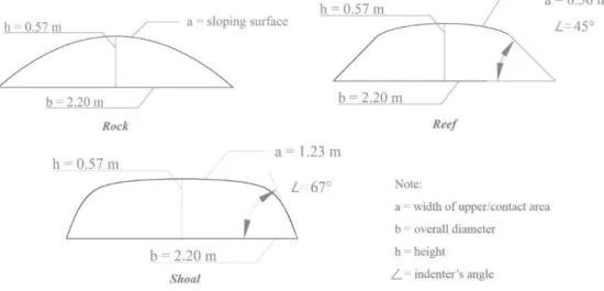
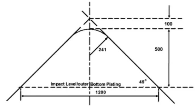
In grounding process, there are several scenarios which involve four different indenters. Rock, reef, and shoal are taken into consideration with the proposed indenter model of Zilakos et al. (2009) is also included. Topologies of rock, reef, and shoal are proposed and described in the present work. Illustration of these indenters are presented in Figure 8, while the previous model is given in Figure 9 to provide adequate comparative data between the proposed indenter and pioneer work in this field. The indenters will be defined as the rigid pyroxene (Christensen, 1996) which material properties of this entity are described in Table 3. This material is considered suitable for the indenters which are defined as seabed since properties of pyroxene are also found in seabed formation. In grounding pro-cess, the indenters are applied velocity 10 m/s in order to move to the designated target locations on the bottom structure. In the first scenario, area on near the center girder, side girder 1 (side 1), side girder 2 (side 2), and two spaces between these longitudinal components are determined as target locations for five cases in ship grounding. Seabed topology of Zilakos is used as indenter in this scenario.
Figure 9: Geometry of conical indenter for grounding simulation (Zilakos et al., 2009).
Property Bulk modulus Density Poisson’s ratio Wave velocity ratio
Value 147,000 MPa 4,002 kg/m3 0.281 1.648
Table 3: Material properties for the indenters. Seabed is assumed as pyroxene material.
As for the second scenario, different seabed topologies which are proposed in the present study will be deployed with the target location on the center girder. Three cases are calculated in this scenario.
In the third scenario, numerical parameters is discussed with several ELT ratios will be imple-mented on the bottom structure. Four ratios are observed to provide tendency of influence which is not only in physical aspect (the first and second scenarios) but also in term of numerical parameter. The target of this scenario is determined to be the center girder as deformation pattern and time calculation are presented in discussion.
6 SIMULATION RESULT
This section is divided into three main sub-sections which each of them describes the calculation results based on specific parameter. Structural behaviour prior and after grounding processes are discussed.
6.1 Location of Target Point
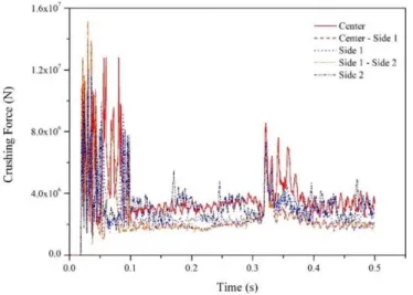
Structural components of the bottom structure is considered highly affect structural behaviour and deformation contour during and after grounding. Rupture energy as presented in Figure 10 described an amount energy that is needed to deform or even destroy involved structure in event of impact. Impact here may occur inform of grounding, stranding and collision. This energy can be evaluated based on the internal energy in the numerical calculation.
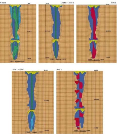
successfully verified with characteristic of the crushing force in Figure 11 where impact on the centre girder give stable fluctuation, especially in range of 0.1 to 0.3 s and 0.35 to 0.5 s. Between these time ranges, the force is observed rises as contact with the transverse floor happens and higher force is needed to penetrate this component. Stable tendency in the mentioned ranges occurs as the indenter is deforming the bottom platting and longitudinal girder without any contact to transverse compo-nent. In term of damage pattern, impact at the side girder number 2, which in term of energy is rivalling the center girder, produced similar damage length with 4.61 m in length and 1 m in width. The shortest tearing is found in impact to the side girder number 1, which actually is not very different with other results. Illustration of the deformation contour is given in Figure 12 for grounding cases to five different locations.
Figure 10: Rupture energy for five impact locations. It can be concluded from this results that the center girder is the hardest to be destroyed in grounding, which is followed by the side girder number 2.
Figure 12: Damage pattern on bottom construction for all cases in location observation.
6.2 Seabed Topology
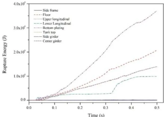
Three topologies are considered for grounding analysis as shape which is influenced by angle and upper width become main parameters of the topologies. As presented in Figures 13 to 15 for rupture energy per structural components during grounding, the rock which is defined as parabolic indenter and has smaller angle than the reef, provides the smallest response than other indenters. This ten-dency is followed by the reef which is an intermediate shape between the rock and shoal. The shoal
Figure 13: Energy for component in grounding with the rock indenter.
Figure 14: Energy for component in grounding with the reef indenter.
Even though the center girder is considered as the strongest structural component that provides good resistance capability on the bottom structure, the shoal which has the largest contact area as influenced by the angle and upper width (notation a in Figure 8) successfully delivers heavy damage to the center girder. The highest energy in Figure 15 indicates that the bottom plating is the main part that is destroyed during grounding and the shoal topology affects deformation in width. As given in Figure 16, approximately tearing 2.3 m in width is obtained after measurement which is largest among of all seabed topologies. Damage of the rock is dominated by deformed bottom plating while the reef provides tearing with width smaller than 1.85 m. These results conclude that despite of all indenters has similar diameter, the critical parameters of the indenter in grounding are upper width which directly contacts with the bottom structure and angle of the indenter that has steeper charac-teristic will produce higher impact and larger deformation area.
Figure 16: Condition of bottom construction after grounding with shoal.
6.3 Meshing Preference
comparative observation on damage contour of two connections i.e. T-connection and X-connection in the bottom structure of the chemical tanker is presented in this section.
(a) (b)
Figure 17: Deformation contour for different meshing size: (a) ELT ratio-10, and (b) ELT ratio-13.
Figure 18: Forces of recommended ratio (ELT ratio: 10) and proposed meshing sizes in this study.
similar contour with no remarkable difference. In other hand, agreement is also shown in term of the crushing force (Figure 18) and energy ratio (Figure 19) which is defined as ratio of total energy in grounding over sum of initial total energy and external work. Results of structural responses which are affected by the expanded range of the ELT ratio 11-13 can be considered provide a satisfaction which no signicant distinction is found. Furthermore, detail of the numerical model and time simula-tion for mesh study is presented in Table 4. For same target structure, it is concluded that time difference between maximum ratio of the recommended range and current study is almost four times bigger.
Figure 19: Characteristic of energy ratio for different ELT ratio in this work.
ELT ratio Element characteristic Time (s)
Size (mm) Total (elem.)
10 120 x 120 126828 4541
11 132 x 132 93111 2469
12 144 x 144 87531 1967
13 156 x 156 72957 1448
Table 4: Model information for several meshing size and its time process for grounding.
Results of the current study can be implemented for other calculations, such as ship collision and grounding with other scenario. Estimation to obtain reasonable result with lower time cost may be conducted with consideration to ELT ratio that influences mesh size on a structure.
7 CONCLUSIONS
behaviour and damage contour. Configuration and setting of the experiment were verified by the impact test in order to ensure the present method could produce reliable results.
Discussion of the numerical results provides several remarkable remarks according to conditions of the bottom structure prior and after fracture. In term of impact location, space between girders is concluded the weakest structure among all of the proposed locations. Structural components in this location do not provide adequate resistance during grounding. Larger damage may occur if this loca-tion is impacted by larger indenter, e.g. shoal. Damage contour indicates a good correlaloca-tion with the energy as longitudinal component, i.e. center or side girders is not exist in this location which reduce structural capability to resist penetration.
In this work which was performed by numerical experiment, cost for material can be reduced as low as possible. However, this method is strictly demanding proper idealization in numerical model and configuration in order to provide good result in reasonable time process. Expanded-mesh-ratio study is presented in the final part of discussion and a recommendation is addressed to reduce time cost with implementation bigger mesh size. ELT ratio 11-13 is considered still provide good result during comparison with ratio 10 which was used by researchers in their previous works on impact engineering. The expanded ratio range is recommended to be applied as alternative solution to reduce time cost in simulation which full-scale model and nonlinear characteristic are implemented as time is essential and vital as reliability in numerical method.
Acknowledgement
This study is successfully presented and published with the support from BK21 plus MADEC Human
Research Development Group, Republic of Korea. The gratitude is addressed to the Laboratory of
Ship Structure and Vibration Analysis, Pukyong National University that provided a full-support for authors during experiment, observation, and manuscript writing. The authors is also grateful to the
Laboratory of Ship Structure and Construction, Diponegoro University for their help and valuable support in initial preparation of this study and experiment.
References
Alsos, H.S., Amdahl, J., (2007). On the resistance of tanker bottom structures during stranding. Marine Structures 20: 218-237.
Alsos, H.S., Amdahl, J., (2009). On the resistance to penetration of stiffened plates, Part I – Experiments. International Journal of Impact Engineering 36: 799-807.
ANSYS, (2013). ANSYS LS-DYNA user’s guide. ANSYS, Inc., Pennsylvania, USA.
Bae, D.M., Prabowo, A.R., Cao, B., Sohn, J.M., Zakki, A.F., Wang, Q., (2016a). Numerical simulation for the collision between side structure and level ice in event of side impact scenario. Latin American Journal of Solids and Structures 13: 2691-2704.
Bae, D.M., Prabowo, A.R., Cao, B., Zakki, A.F., Haryadi, G.D., (2016b). Study on collision between two ships using selected parameters in collision simulation. Journal of Marine Science and Application 15: 63-72.
Bathe, K.J., (1996). Finite element procedures. Prentice-Hall, Inc., New Jersey, USA.
Haris, S., Amdahl, J., (2013). Analysis of ship-ship collision damage accounting for bow and side deformation interac-tion. Marine Structures 32: 18-48.
Heinvee, M., Tabri, K., (2015). A simplified method to predict grounding damage of double bottom tankers. Marine Structures 43: 22-43.
Lützen, M., Simonsen, B.C., (2003). Grounding damage to conventional vessels. Proceedings of the World Maritime Technology Conference, San Fransisco, US.
Otto, S., Pedersen, P.T., Samuelides, M., Sames, P.C., (2002). Element of risk analysis for collision grounding of a RoRo passenger ferry. Marine Structures 15: 461-474.
Ozguc, O., Das, P.K., Barltrop, N., (2005). A comparative study on the structural integrity of single and double side skin bulk carriers under collision damage. Marine Structures 18: 511-547.
Prabowo, A.R., Bae, D.M., Sohn, J.M., Cao, B., (2016a). Energy behavior on side structure in event of ship collision subjected to external parameters. Heliyon 2: e00192.
Prabowo, A.R., Bae, D.M., Sohn, J.M., Zakki, A.F., (2016b). Evaluating the parameter influence in the event of a ship collision based on the finite element method approach. International Journal of Technology 4: 592-602.
Prabowo, A.R., Bae, D.M., Sohn, J.M., Zakki, A.F., Cao, B., (2017c). Rapid prediction of damage on a struck ship accounting for side impact scenario models. Open Engineering 7: 91-99.
Prabowo, A.R., Bae, D.M., Sohn, J.M., Zakki, A.F., Cao, B., Cho, J.H. (2017b). Effects of the rebounding of a striking ship on structural crashworthiness during ship-ship collision. Thin-Walled Structures 115: 225-239.
Prabowo, A.R., Bae, D.M., Sohn, J.M., Zakki, A.F., Cao, B., Wang, Q., (2017a). Analysis of structural behavior during collision event accounting for bow and side structure interaction. Theoretical and Applied Mechanics Letters 7: 6-12. Simonsen, B.C., (1997a). Mechanics of ship grounding. Ph.D. Thesis, Department of Naval Architecture and Offshore Engineering, Technical University of Denmark, Lyngby, Denmark.
Simonsen, B.C., (1997b). Ship grounding on rock – I. Theory. Marine Structures 10: 519-562.
Wierzbicki, T., Thomas, P., (1993). Closed form solution for wedge cutting force through thin metal sheets. Interna-tional Journal of Mechanical Sciences 35: 209-229.
Wiśniewski, K., Kołakowski, P., (2003). The effect of selected parameters on ship collision results by dynamic FE simulations. Finite Elements in Analysis and Design 39: 985-1006.
