Localization of Damage in Beams Using
Interferometric Techniques
H. LOPES, J. RIBEIRO, J. V. ARAÚJO DOS SANTOS
and N. M. M. MAIA
ABSTRACT
Two interferometric techniques and their applications in structural damage identification are presented in this paper. Out-of-plane displacement fields of modal response are measured with a pulsed electronic speckle pattern interferometric system (ESPI). The modal rotation fields, defined as the spatial derivative of the displacement field, are measured with a pulsed speckle shearography system. The measurements using these two interferometric systems are compared with measurements from experimental modal analysis and results from finite element analysis. This comparison shows that these two interferometric techniques, which allow non-contact, full-field measurements, are well suited to the measurement of modal response. A damaged beam with free-free boundary conditions is analyzed. The damages studied are small cuts perpendicular to the beams longitudinal axis. The bending moments and shear forces, which are related to the second and third order spatial derivatives of the modal displacement field, in the undamaged and damaged states are computed using numerical differentiation techniques. The damage is localized by looking for maximum values and/or perturbations of damage indicators based on bending moments and shear forces along the beam. The pulsed speckle shearography system leads to a significant improvement in the computation of bending moments and shear forces and, therefore, better damage localizations than the ones obtained with the pulsed ESPI system.
_____________
H. Lopes and J. Ribeiro, ESTIG – Instituto Politécnico de Bragança, Campus de Sta. Apolónia, Apartado 134, 5301-857 Bragança, Portugal
J.V. Araújo dos Santos and N.M.M. Maia, IDMEC/IST – Universidade Técnica de Lisboa, Av. Rovisco Pais, 1049-001 Lisboa, Portugal
6th European Workshop on
INTRODUCTION
Structural damage identification based on vibration characteristics, which encompasses detection, localization and quantification, is a very active research topic. Thus, many methods can be found in the literature [1]. One of the most successful and well established is the mode shape curvature method, presented by Pandey et al. [2]. It has been improved [3-4], generalized to frequency response function data [5] and applied to composite structures [6-9]. Usually the experimental data used are sparse displacement fields that need to be numerically differentiated. The differentiation of these sparse measurements gives raise to propagation and amplification of experimental noise and, therefore of poor damage localizations. One way to improve the damage localization is to use full-field experimental techniques.
In this paper, two full-field, non-contact and high resolution optical techniques are presented, validated and applied to localize damage in a beam. The first one is the electronic speckle pattern interferometry (ESPI) and allows the measurement of displacement fields. Speckle shearography is used to obtain the spatial derivatives of displacement, i.e the rotation field. These techniques have their origins in holographic interferometry [10]. They are based on the comparison of two patterns or phase maps generated by the coherent superposition of two wavefronts. Each of these phase maps refers to a state of an object with a rough surface. Considering that the first phase map corresponds to the undeformed state and the second one to the deformed state, it is possible to measure the motion of the objects surface. The modal response of an object can be assessed by using a pulsed laser in the experimental set-up of these techniques.
Two experimental set-ups were implemented to measure the stationary harmonic motion at the first two natural frequencies of free-free beams, acoustically excited, with the ESPI and shearography techniques. These measurements are compared with those obtained using standard experimental modal analysis and the finite element method. Two damage indicators, based on the distribution of bending moments and shear forces, are presented and applied to the damage localization of two cuts in an aluminium beam. Since the bending moments are related to the second and third derivatives of the displacement, the data from the ESPI measurements must be differentiated twice and thrice, respectively. However, when one uses the data obtained with the shearography system, the bending moment and shear force is computed respectively by differentiating once and twice the rotations. Because of this decrease in the order of the needed differentiations, which diminishes the propagation and amplification of noise, the pulsed speckle shearography system presents better damage localizations than the pulsed ESPI system.
VALIDATION OF INTERFEROMETRIC TECHNIQUES
preliminary measurements showed that the influence of the accelerometer mass in an aluminum beam is substantial. In order to minimize this problem, instead of an aluminum beam, a stainless steel beam was studied.
Experimental Modal Analysis
A stainless steel beam 450 mm long, 71 mm width and 10 mm thick was analyzed free in space. The free-free conditions were accomplished by suspending the beam with rubber bands. Transient type excitations were applied using an impact hammer and the negative exponential responses were measured by an accelerometer of 2.4 g. The excitations were applied at 31 points along the half width of beam, while the responses were measured at one of the beams end. This analysis was performed in a 0 Hz to 1 kHz frequency band, with a resolution of 156.25 mHz.
The natural frequencies, damping ratios and modal participation factors were obtained through the polyreference technique in the time domain. The corresponding mode shapes were obtained by least square fitting using the polyreference technique in the frequency domain [11-12]. This analysis was performed with the 31 measured FRFs. Two natural frequencies were identified in the frequency band and their respective mode shapes were constructed. The first two natural frequencies are 260.95 Hz and 718.72 Hz with damping ratios of 0.084% and 0.038%, respectively.
The modal model is created from the identified modal parameters above. This model should describe the vibrational behavior of the structure. The validation of this model is performed by comparing the synthesized and measured FRF and the modal assurance criteria (MAC) [12-13]. The MAC measures the level of orthogonality of different modes. Ideally, the diagonal elements of the MAC matrix should take a value of 100%, while the off-diagonal elements should be zero. In the present case, the diagonal elements have a value of 100.00% and the off-diagonal are 0.26%.
ESPI and Shearography
To perform dynamic measurements, the pulsed ESPI system, also known as pulsed TV holography, uses holographic interferometry principles to compare two states of an object in a very short time interval. The present system uses a double pulse Ruby laser to generate a pair of impulses with 690 nm wavelength, separated by 400 microseconds. The double esposure holograms are recorded by a 512 x 512 resolution CCD digital camera. These holograms contain information of the phase differences of two wave fronts.
The beam was suspended and excited acoustically at each natural frequency using a loudspeaker. At each frequency, the signal amplitude was adjusted in order to fit the amplitude of the vibration within the range of the measurement system. This signal is also used to synchronize the laser trigger and the harmonic vibration of the beam. As the beam is free in space, it presents both elastic and rigid body modes. The elastic mode shape is confined from the rigid body motion, which has small amplitude and lower frequency, i.e., a larger period, since the impulses are separated by only 400 μs.
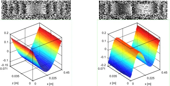
first mode shapes. These mode shapes, also presented in Figure 1, are obtained by post-processing the phase maps using filtering and unwrapping techniques [14, 17]. One can define the displacement field of a beam mode shape as a vector of norm one by taking the amplitudes of the longitudinal axis at half width of the beam. The displacement fields thus obtained and the ones obtained by experimental modal analysis and finite element analysis show an excellent agreement (Figure 2). Small discrepancies at the edge of the beam are observed between the experimental modal analysis and the finite element results, which may be related to the presence of the accelerometer.
0
0.225 0.45
0 0.035 0.071
-0.15 -0.1 0 0.1 0.2
x [m]
z [m] 0
0.225 0.45
0 0.035 0.071
-0.2 -0.1 0 0.1 0.2
x [m] z [m]
Figure 1. Phase maps and displacement fields of the first two mode shapes using the pulsed ESPI system.
0 0.1125 0.225 0.3375 0.45 -0.15
-0.1 0 0.1 0.2
x [m]
EMA
ESPI
FEM
0 0.1125 0.225 0.3375 0.45 -0.2
-0.1 0 0.1 0.2
x [m]
EMA ESPI
FEM
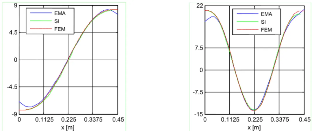
Figure 2. Displacement fields of the first two mode shapes using experimental modal analysis (EMA), the pulsed ESPI system, and the finite element method (FEM).
The pulsed speckle shearography system is based on a Mach-Zehnder interferometer and, like the ESPI system, uses a double pulsed laser and a CCD digital camera to register two holograms in two consecutive instants. The phase map relative to the rotation field, i.e. the displacement field gradient, is constructed based on these two holographic recordings.
rotations into the measurement range. The shearography system is more insensitive to uniform displacements than the ESPI system, therefore allowing a better confinement of rigid body motions.
Figure 3 shows the phase maps of the rotation fields relative to the first two modes of the undamaged free-free beam. As in the ESPI technique, by post-processing these phase maps we obtain the vectors that define the corresponding rotation fields.
Figure 3. Phase maps of the first two mode shapes using the pulsed speckle shearography system.
These rotation fields are compared with the ones obtained by numerical differentiation of the experimental modal analysis displacement fields and the rotation fields computed by finite elements. There is a relatively fair correlation among the three kinds of rotation fields (Figure 4). Similarly to the ESPI results (see Figure 2), we observe some discrepancies between the modal and the finite element fields at the edge of the beam.
0 0.1125 0.225 0.3375 0.45 -9
-4.5 0 4.5 9
x [m]
EMA
SI
FEM
0 0.1125 0.225 0.3375 0.45 -15
-7.5 0 7.5 22
x [m]
EMA SI
FEM
Figure 4. Rotation fields of the first two mode shapes using experimental modal analysis (EMA), the pulsed speckle shearography system (SI), and the finite element method (FEM).
DAMAGE LOCALIZATION
An aluminum beam was chosen as a test structure to localize damage. The first two natural frequencies of the beam are determined by classical experimental modal analysis procedures and the mode shapes are obtained using a pulsed ESPI and pulsed speckle shearography systems.
x y
p1
c1
p2
c2
l2
l1
The damage studied consists of two small cuts perpendicular to the beams longitudinal axis. The free-free aluminum beam analyzed is L = 260 mm long, b = 45 mm wide and h = 6 mm thick. The cuts are located at l1 = 75 mm and l2 = 130 mm with dimensions p1 = 0.65 mm, c1 = 4 mm, p2 = 0.75 mm, c2 = 0.75 mm (Figure 5).
The damage indicators used in this work are the bending moment indicator (BMI) and shear force indicator (SFI). These indicators are defined, respectively, by [18]:
, ) ( min ) ( max ) ( ) ( ~ ) ( x M x M x M x M xBMI l l
l
) ( min ) ( max ) ( ) ( ~ ) ( x V x V x V x V xSFI l l
l
(1)
where the tilde denotes the damaged beam quantities and xl is the coordinate where
the indicator is computed.
The relations among the displacement and rotation fields, y(x) and (x), the bending moment M(x) and the transverse force V(x) are defined considering the Euler-Bernoulli beam theory:
3 3 2 2 ) ( ) ( , ) ( ) ( dx x y d EI x V dx x y d EI x
M or
2 2 ) ( ) ( , ) ( ) ( dx x d EI x V dx x d EI x
M (2)
The first two relations in (2) are used with the measurements made with the ESPI system, as this technique gives us the out-of-plane displacements, whereas the last two
relations are applied to the shearography measurements.
0 0.065 0.13 0.195 0.26
0 0.1 0.2 0.3 0.4 0.5 Bending moment x [m] BM I
1st mode: ESPI
1st mode: SI 1st mode: FEM
0 0.065 0.13 0.195 0.26
0 0.2 0.4 0.6 0.8 1 Shear force x [m] SF I
1st mode: ESPI
1st mode: SI 1st mode: FEM
0 0.065 0.13 0.195 0.26
0 0.05 0.1 0.15 0.2 0.25 0.3 0.35 Bending moment x [m] BM I
2nd mode: ESPI
2nd mode: SI 2nd mode: FEM
0 0.065 0.13 0.195 0.26
0 0.1 0.2 0.3 0.4 0.5 0.6 Shear force x [m] SF I
2nd mode: ESPI
2nd mode: SI 2nd mode: FEM
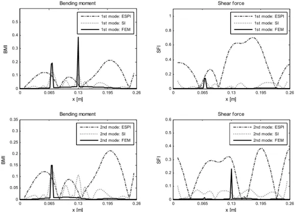
The computed BMI and SFI indicators of the first and second mode shapes relative to the measurements of the pulsed ESPI system, the pulsed speckle shearography system and results from finite element analysis are presented in Figure 6. The best damage localization is the one obtained with the pulsed speckle shaerography system and the BMI indicator. Besides showing a similar trend to the BMI distribution computed with finite element data, the BMI distribution computed with the pulsed speckle shearography measurements shows maximum values at the beam sections where the cuts are located. The cuts are not localized using the SFI indicators, because the shear force is obtained by differentiating twice the rotation field measured with the shearography system and thrice the displacement field measured with the ESPI system. Since these differentiations are performed by simultaneously applying signal differentiation and high frequency filtering techniques, the signal high frequencies due to damage, which are usually mixed up with high frequency measurement noise, are eliminated.
CONCLUSIONS
Two interferometric techniques and their applications to damage localization of cuts in beams were described in this paper. The measurements of the displacement and rotation fields using ESPI and speckle shearography systems, respectively, and subsequent application of a numerical differentiation method, allowed us to successfully determine the bending moments and shear forces of modal responses of a beam free in space. The reduction in one order of the spatial derivative needed to compute the bending moments and the shear forces by using the pulsed speckle shearography system leads to a significant improvement in the localization of damage.
ACKNOWLEDGEMENTS
The authors greatly appreciate the financial support of FCOMP-01-0124-FEDER-010236 through Project Ref. FCT PTDC/EME-PME/102095/2008.
REFERENCES
1. J.V. Araújo dos Santos, N.M.M. Maia, C.M. Mota Soares, C.A. Mota Soares, Structural damage identification: A survey, in Trends in Computational Structures Technology, chapter 1, Stirlingshire, UK: Saxe-Coburg Publications, 1-24, 2008.
2. A.K. Pandey, M. Biswas, M.M. Samman, Damage detection from changes in curvature mode shapes, J. Sound Vib., 145(2), 321-332, 1991.
3. H. Guan, V. Karbhari, Improved damage detection method based on element modal strain damage index using sparse measurement J. Sound Vib., 309, 465-494, 2008.
4. M. Chandrashekhar, R. Ganguli, Damage assessment of structures with uncertainty by using mode-shape curvatures and fuzzy logic, J. Sound Vib., 326 (3-5), 939-957, 2009.
5. R.P.C. Sampaio, N.M.M. Maia, J.M.M. Silva, Damage detection using the frequency-response-function curvature method, J. Sound Vib, 226, 1029-1042, 1999.
7. J.V. Araújo dos Santos, H.M.R. Lopes, M. Vaz, C.M. Mota Soares, C.A. Mota Soares, M.J.M. de Freitas, Damage localization in laminated composite plates using mode shapes measured by pulsed TV holography, Compos. Struct., 76, 272-281, 2006.
8. H.M.R. Lopes, J.V.A. Araújo dos Santos, C.M. Mota Soares, R.J.M. Guedes, M. Pires Vaz, A numerical-experimental method for damage location based on rotation fields spatial differentiation, Comput. Struct., 89, 1754-1770, 2011.
9. D. Montalvão, N.M.M. Maia, A.M.R. Ribeiro, A review of vibration-based structural health monitoring with special emphasis on composite materials, Shock Vib. Digest, 38, 295-324, 2006. 10. J.N. Butters, J.A. Leendertz, Speckle pattern and holographic techniques in engineering metrology,
Opt. Laser Technol., 3, 26-30, 1971.
11. C.M. Harris, Shock and Vibration Handbook, 4th edition, Mcgraw-Hill, New York, 1995.
12. N.M.M. Maia, J.M.M. Silva, Theoretical and Experimental Modal Analysis, John Wiley & Sons, New York, 1997.
13. D.J. Ewins, Modal Testing: Theory and Practice, Research Studies Press Ltd., Tauton, Somerset, England, 1984
14. T. Kreis, Handbook of Holographic Interferometry: Optical and Digital Methods, Weinheim, Wiley-VCH, 2005.
15. G. Pedrini, Y.-L. Zou, H.J. Tiziani, Quantitative evaluation of digital shearing interferogram using the spatial carrier method, Pure Appl. Opt., 5, 313-321, 1996.
16. F. Santos, M. Vaz, J. Monteiro, A New Set-up for Pulsed Digital Shearography Applied to Defect Detection in Composite Structures, Opt. Lasers Eng., 42(2), 131-140, 2004.
17. D.C. Ghiglia, M.D. Pritt, Two-Dimensional Phase Unwrapping: Theory, Algorithms, and Software, Wiley, New York, 1998.
Back to results | 1 of 1
Search Alerts My list Settings
| Export | Download | More...
View references (18)
View in search results format Proceedings of the 6th European Workshop - Structural Health Monitoring 2012, EWSHM 2012
Volume 1, 2012, Pages 198-205
6th European Workshop on Structural Health Monitoring 2012, EWSHM 2012; Dresden; Germany; 3 July 2012 through 6 July 2012; Code 102922
Localization of damage in beams using interferometric techniques
(Conference Paper)
Lopes, H.a, Ribeiro, J.a, Araújo Dos Santos, J.V.b, Maia, N.M.M.b
a ESTIG, Instituto Politécnico de Bragança, Campus de Sta. Apolónia, Apartado 134, 5301-857 Bragança, Portugal
b IDMEC, IST, Universidade Técnica de Lisboa, Av. Rovisco Pais, 1049-001 Lisboa, Portugal
Abstract
Two interferometric techniques and their applications in structural damage identification are presented in this paper. Out-of-plane displacement fields of modal response are measured with a pulsed electronic speckle pattern interferometric system (ESPI). The modal rotation fields, defined as the spatial derivative of the displacement field, are measured with a pulsed speckle shearography system. The measurements using these two interferometric systems are compared with measurements from experimental modal analysis and results from finite element analysis. This comparison shows that these two interferometric techniques, which allow non-contact, full-field measurements, are well suited to the measurement of modal response. A damaged beam with free-free boundary conditions is analyzed. The damages studied are small cuts perpendicular to the beams longitudinal axis. The bending moments and shear forces, which are related to the second and third order spatial derivatives of the modal displacement field, in the undamaged and damaged states are computed using numerical differentiation techniques. The damage is localized by looking for maximum values and/or perturbations of damage indicators based on bending moments and shear forces along the beam. The pulsed speckle shearography system leads to a significant improvement in the computation of bending moments and shear forces and, therefore, better damage localizations than the ones obtained with the pulsed ESPI system.
Reaxys Database Information
|
ISBN: 978-394028341-2 Source Type: Conference Proceeding Original language: English
Document Type: Conference Paper
Sponsors: EMBRAER S. A.,WOLFEL Beratende Ingenieure GmbH + Co. KG,Sachsisches Staatsministerium fur
Wissenschaft und Kunst
References (18)
Page Export | Print | E-mail | Create bibliography
Cite
Infor
Rela
Inte iden Lope (201
Imp shea Lope (201
Loc and Lope (201
View
Find
A