Design and Optimisation of Photonic Crystal Fibres
for Applications in Communication Systems
H. Ademgil and S. Haxha
Abstract- Photonic crystal fibre (PCF)s with zero chromatic
dispersion at the telecommunication wavelength is reported. The PCF design parameters, such as the effects of air holes and structural design parameters on the effective index, effective mode area, confinement losses and chromatic dispersion, have been carefully investigated by using the full vectorial finite element method. It is demonstrated that it is possible to achieve low loss PCF with desired dispersion for the telecommunication wavelength range of 1.2 to 1.8 µm.
Index terms
-
Photonic crystal fibres, confinement losses,chromatic dispersion, communication systems.
I. INTRODUCTION
Photonic crystal fibre (PCF), known as ‘holey’ fibre, is a microstructured fibre consisting of air hole arrays that run along the waveguide length of the fibre, which have unique properties that are not realised in standard optical fibre [1, 2]. Increasing interest is being show in studying such PCFs, and many research groups around the world are demonstrating various kinds of PCFs with regular or irregular structures, with solid or hollow cores, using various materials such polymer or silicon. The PCFs show very interesting characters, such as a wide wavelength range which can be utilised to transmit ultra-short pulses [3], zero dispersion wavelength in the 800 nm region suitable for nonlinear applications, for example supercontinuum generation [4], and extraordinary dispersion properties at visible and near infrared wavelengths [5]. An additional important characteristic of PCFs is their strong birefringence induced by the size and geometrical arrangement of air holes. As a result of useful properties, growing interest is being shown in PCFs for a range of applications in optical signal processing, sensing, and optical communication systems.
In this study, a full vectorial finite element method (FEM) has been employed to investigate modal properties of the PCF. The FEM is considered to be a powerful numerical technique to study various types of photonic waveguide devices, including PCFs [6-8]. The anisotropic perfectly matched layers (PML) as boundary conditions have been introduced to observe propagation characteristics of leaky modes in the PCF.
Manuscript received March 27, 2007.
The authors are with the Broadband and wireless communication group, Department of Electronics
University ofKent, Canterbury CT2 7 NT, UK Tel: +44 (0) 1273 827257, Fax: +44 (0) 1227 456084 Email: [email protected]
Dispersion and loss properties can also be accurately calculated. In this paper, the effect of the air hole size on the propagation characteristics such as the effective index, confinement loss and chromatic dispersion of the fundamental mode as well as the wavelength operation has been fully investigated.
II. THEORY
The PCF cross section, with the finite number of air holes is divided into homogeneous subspaces where Maxwell’s equations are solved by accounting for the adjacent subspaces. Using the anisotropic PML [9] from the Maxwell equations the following vectorial equation is derived:
∇
×
(∇
×
E)- 2 2 0n
k
E = 0 (1)
where k0 = 2π/λ is the wave-number in the vacuum, λ being the wavelength, and n is the refractive index of medium.
The fundamental mode is propagating in the core region. Due to a finite number of layers of air holes, the optical mode leakage from the core region into the outer air hole region is inevitable and the confinement loss due to the extent of the cladding is taking place. The confinement loss is calculated from the imaginary part of the complex effective index,
n
eff using:Conf. loss =
( )
Im( )
eff 8.6860Im( )
eff 10 ln 40 n k n = λ π[dB/m] (2)
where Im is the imaginary part of the neff.
Control of the chromatic dispersion in PCFs is critical for applications to optical communication systems. The Chromatic dispersion consists of material dispersion and waveguide dispersion, which can be calculated from the neff values against the wavelength using [5].
[
]
2 const. λ n eff 2 2 M 2λ
n
c
λ
n
c
λ
M∂
∂
⎟
⎠
⎞
⎜
⎝
⎛
−
∂
∂
⎟
⎠
⎞
⎜
⎝
⎛
−
=
Re(
)
( )=D
λ
(3)Proceedings of the World Congress on Engineering 2007 Vol I WCE 2007, July 2 - 4, 2007, London, U.K.
where c is the speed of light, Re (neff) is the real part of the effective index and nM is dependent on λ in dispersive media. In the case when nM(λ) = const., material dispersion is neglected.
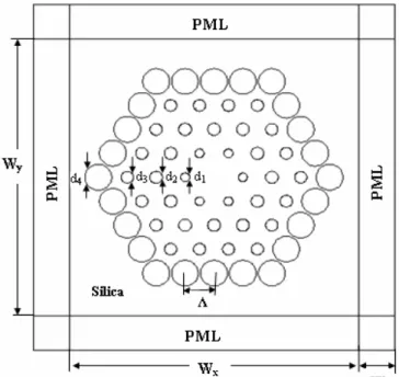
Fig.1. Schematic cross section of the PCF with four rings of 60 air holes
III. RESULTSAND DISCUSSIONS
Figure 1 shows a schematic diagram of the PCF, consisting of four rings of arrays of air holes arranged in a silica background whose index of refraction is 1.45. The diameter of air holes and their pitch is denoted with d and Λ, respectively. Owing to the symmetry of the structure along both x and y directions, only one-quarter of the fibre cross section is divided into curvilinear hybrid elements. In all simulations the computational window area Wx/2
×
Wy/2has been taken to be 8µm
×
8µm and this has been terminated by a PML whose width, W, is 2.0 µm.Figure 2 illustrates field profile of the dominant Ex
component of the fundamental x
11
HE mode, where
Λ=1.6µm, d1/Λ=0.312, d2/Λ=0.43, d3/Λ= 0.419, and d4/
Λ=0.92 at the operating wavelength λ=1.55µm. Fig. 3 shows the variation of the real part of the complex effective index with the wavelength λ. As may be observed from this figure, effective index of the fundamental mode decreases monotonically when wavelength increases.
Fig.2. The field profile of the dominant Excomponent of the
fundamental HE11x mode, where Λ=1.6µm, d1/Λ=0.312, d2/
Λ=0.43, d3/Λ= 0.419, d4/Λ=0.92 at the operating wavelength
λ=1.55µm.
Fig.3. Variation of the real part of the complex effective index of the x
11
HE mode with the wavelength λ.
The confinement loss of the fundamental mode has been computed from the imaginary part of the complex effective index, neff, and as may be noted from Fig.4, the confinement loss decreases rapidly when the operating wavelength decreases. The confinement loss is 0.0082 dB/m at communication wavelength 1.55 µm.
Proceedings of the World Congress on Engineering 2007 Vol I WCE 2007, July 2 - 4, 2007, London, U.K.
Fig.4. Variation of confinement loss with the wavelength, λ, where Λ=1.6µm, d1/Λ=0.312, d2/Λ=0.43, d3/Λ= 0.419, d4/Λ=0.92.
Another key factor in designing PCFs is the effective mode area. The effective mode area, Aeff is related to the effective area of the core area, which is calculated using [10],
(
)
∫∫
∫∫
=dxdy E
dxdy E
Aeff 4
2 2
(4)
A low effective area provides a high density of power required for non-linear effects to be significant. However, the effective area can also be related to the spot-size, with the Gaussian width w, through Aeff = πw2, and thus it is also important in the context of confinement loss, micro-bending loss macro-bending loss, splicing loss, and numerical aperture [11]. Here in this paper we have investigated the effective mode area of the proposed PCF structure by varying the operating wavelength. Figure 5 shows the variation of the effective mode area Aeff, with the wavelength. It can be noted that Aeff is 9.021 µm2 at the communication window of 1.55 µm. It is worth notifying that the effective area is smaller than that of conventional fibres at 1.55µm wavelength. The PCFs with nearly zero ultraflattened dispersion have relatively small effective area and would be useful for some nonlinear applications, such as supercontinuum generation.
In the shorter operating wavelengths, mode is more confined into the core region than in the longer wavelengths, and the chromatic dispersion property is directly affected by the inner air-hole rings. In the longer wavelengths the effective core area is increases and the chromatic dispersion is affected not only in the inner rings but also in the outer rings, especially when the hole to hole spacing (Λ) is small.
Fig.5. Variation of effective mode area with wavelength
Figure 6 shows the reported ultra-low and ultra-flatted chromatic dispersion values of PCFs with four rings of air hole, where Λ=1.6 µm, d1/ Λ=0.312, d2/ Λ=0.43, d3/ Λ= 0.419, d4/Λ=0.92 (solid line) and d1/Λ=0.312, d2/Λ=0.43, d3/Λ= 0.468, d4/Λ=0.92 (dashed line). As can be observed from this figure, chromatic dispersion close to zero for a wide wavelength has been achieved. As may be seen from the figure chromatic dispersion values between the wavelengths from 1.35 µm to 1.8 µm can be controlled by changing the size of the air holes of the third ring. In this case almost zero dispersion has been achieved at 1.55 µm wavelength. It can also be observed that dispersion values for the wavelength form 1.5 µm to 1.65 µm changes between 0.4 and -0.11 ps/km.nm. Negative dispersion has also been obtained around 1.6 µm.
Fig.6. Variation of Chromatic dispersion with wavelength where Λ=1.6µm, d1/Λ=0.312, d2/Λ=0.43, d3/Λ= 0.419, d4/
Λ=0.92 (solid line) and d1/ Λ=0.312, d2/ Λ=0.43, d3/ Λ= 0.468, d4/Λ=0.92 (dashed line).
Proceedings of the World Congress on Engineering 2007 Vol I WCE 2007, July 2 - 4, 2007, London, U.K.
IV. CONCLUSION
In this study, a new structure of PCF was proposed and analyzed by using a full-vector FEM. The effective index, the confinement loss, the effective mode area and the chromatic dispersion of the fundamental mode of this structure have been successfully investigated. Low losses with ultra-low and desired chromatic dispersion in the telecommunication wavelength are reported. It was shown that it is possible to achieve zero dispersion at 1.55 µm wavelength.
REFERENCES
[1] J. C. Knight, T.A. Birks, P. St. .J Russell, “All-silica single-mode optical fibre with photonic crystal cladding,” Optics Letters, vol. 21, pp. 1547-1549 1996.
[2] E. Yablonovitch, “Inhibited spontaneous emission in
solid state physics and electronics,” Phys. Rev. Lett., vol. 58, pp. 2059-2062, 1987.
[3] A. Ferrando, E. Silvester, J. J. Miret, and P. Andres, “Nearly zero ultra flattened dispersion in photonic crystal fibers,” Optics Letters, vol. 25, pp. 790-792 2000.
[4] J. K. Rank, R. S. Windeler, and A. J. Stentz, “Visible continuum generation in air-silica microstructure optical fibers with anomalous dispersion at 800 nm,” Optics Letters., vol. 25, pp. 25-27, 2000.
[5] A. Bjarkev, J. Broeng, and A. Sanchez Bjarkev, “Photonic Crystal Fibres” Kulver Academic, 2003. [6] B. M. A. Rahman, V. Haxha, S. Haxha, K. T. V.
Grattan, “Design Optimisation of Polymer Electro-optic Modulators, ” IEEE J. Lightwave Technology, vol. 24, pp. 3506-3513, 2006.
[7] S. Haxha, E. O. Ladele, M. Mjeku, F. AbdelMalek, and B. M.A. Rahman, “Optimisation of compact lateral, vertical, and combined tapered spot-size converters by use of the beam-propagation method”, Applied Optics, vol. 45, pp. 288-296, 2006.
[8] K. Saitoh and M. Koshiba, “Full-vectorial Imaginary-Distance Beam Propagation Method Based on a Finite Element Scheme: Application to Photonic Crystal Fibres,” IEEE J. Quantum Electron., vol. 38, pp. 927-933, 2002.
[9] K. Saitoh, and M. Koshiba, “Full vectorial finite element beam propagation method with PML for anisotropic optical waveguides,” IEEE J. Lightwave Tech., vol. 19, pp. 405-413, 2001.
[10]Niels Asger Mortensen and Jacob Riis Folkenberg, “Low-loss criterion and effective area considerations for photonic crystal fibres,” J. Opt. A: Pure Appl. Opt., vol. 5, pp. 163–167, 2003.
[11]Niels Asger Mortensen, “Effective area of photonic crystal fibers” Optics Express, vol. 10, pp. 341-348, 2002.
Proceedings of the World Congress on Engineering 2007 Vol I WCE 2007, July 2 - 4, 2007, London, U.K.