Abstract—This paper presents a new circular photonic crystal
fiber (C-PCF) for effective dispersion compensation covering E to L wavelength bands ranging from 1360-1625 nm. To investigate its guiding properties, finite element method (FEM) with a perfectly matched layer absorbing boundary condition is used. From our numerical simulation, it is found that the designed C-PCF simultaneously shows a large negative dispersion of about -248.65 to -1069 ps/(nm.km) over E to L wavelength bands and a relative dispersion slope (RDS) exactly equal to that of a single mode fiber (SMF) at 1.55 µm wavelength. It is also found that residual dispersion after compesating 40 km long SMF is within ±62 ps/nm which ensures application of C-PCF in high speed WDM system. Besides, dispersion slope, slope compensation ratio, effective area and confinement loss of the proposed C-PCF are also evaluated and discussed.
Index Terms—Chromatic dispersion, Dispersion compensating fiber, Finite element method, Photonic crystal fiber.
I. INTRODUCTION
In fiber optic communication systems, dispersion limits the maximum transmission distance and the
bit rate [1]. The dispersion causes the broadening of optical pulses when transmitted through the fiber.
Thus, the dispersion must be compensated in the long distance optical data transmission system to
nullify the pulse broadening. Presently, dispersion compensating fibers (DCFs) are widely used and
commercially available for dispersion compensation which is designed to have large negative
dispersion [2-7]. However, DCF using conventional fibers give a high negative dispersion only at a
particular wavelength but not over wide band [8]. In order to reduce the length of DCF and hence to
reduce the cost significantly, we need high negative dispersion [7, 9]. However, it is difficult to
achieve high negative dispersion using the conventional DCFs. In addition, high negative dispersion
of DCFs is needed to be achieved over a wide range of wavelength so that it can be used in broadband
communication system. Hence, compensation of dispersion and dispersion slope are simultaneously
required. Recently, photonic crystal fibers (PCFs) or holey fibers or microstructured optical fibers
consists of a microscopic array of air channels running down their length that make a low index
cladding around the undoped silica core [10] have gained attentions in the field of dispersion
A new circular photonic crystal fiber for
effective dispersion compensation over E to L
wavelength bands
M. M. Haquea,*, M. S. Rahmana, M. Samiul Habibb, M. Selim Habibb, S. M. A. Razzakb
a
Dept. of Electrical and Electronic Engineering, Khulna University of Engineering & Technology, Khulna-9203.
b
management of transmission fiber, sensing and telecom applications [10-11]. Now-a-days, it has
become a promising candidate especially as a dispersion compensator as it allows us to tune
dispersion properties in a way which is not possible for the conventional fibers.
To compensate dispersion of SMF, different types of PCF structures have already been proposed in
[12-22]. PCF with hexagonal structure employing nine air-hole rings is proposed in [12] to
compensate dispersion over S+C+L band but the negative dispersion is not sufficiently large, number
of rings are relatively high and relative dispersion slope (RDS) is not perfectly matched with RDS of
SMFs. Modified Octagonal-PCF using six air-hole rings has been studied in [13] which achieves
negative dispersion of only -239.5 ps/(nm.km) at 1.55 µm with 90% slope matching. Although, good
dispersion compensating characteristics are obtained by [14, 20] but available bandwidth for
dispersion compensation is narrow and no effort was made to match RDS with the RDS of SMF. PCF
with dual concentric core without Ge doping have been proposed in [17-19] but insufficient
bandwidth for dispersion compensation is further noticed. Dual concentric core fibers have been
proposed in [21-22] for broadband dispersion compensation of SMF, but the problem owing to Ge
doping still remains. Recently, PCF for broadband dispersion compensation of SMF have been
proposed [15, 23] using five air-hole rings. PCF with square-lattice [15] reports a negative dispersion
of -204.4 ps/(nm.km) and an RDS of 0.003543nm1at 1.55 µm wavelength which is not exactly equal
with SMF's RDS. Moreover, PCF with hexagonal structure in [23] shows perfect RDS matching with
SMF but exhibits insufficient negative dispersion of -130 to -360 ps/(nm.km) in a 1.30-1.60 µm
wavelength range which will ultimately increase the length of designed DCF. As a solution, there is a
still need for large negative dispersion over a broad range of wavelength and at the same time RDS of
0.0036nm1at =1.55 µm.
In this study, we report a new circular photonic crystal fiber using five air-hole rings which
simultaneously gives high negative dispersion over a wide range of wavelength as well as perfectly
matched RDS with that of SMF using FEM. Simulation results show that it is possible to achieve
large negative dispersion of about -248.65 to -1069 ps/(nm.km) over E to L telecommunication band
as well as RDS of 0.0036nm1at =1.55 µm, better dispersion slope and slope compensation ratio
respectively. It is expected that the proposed C-PCF would be the viable alternative for dispersion
compensator to compensate the positive dispersion and dispersion slope of SMF.
II. STRUCTURE OF THE PROPOSED C-PCF
Fig. 1 represents air-hole distribution of the proposed dispersion compensating C-PCF. The
proposed C-PCF contains only five air-hole rings and the material of studied is taken to be silica. The
air-holes on the 1st ring are rotated at an angle 600 while air-holes on the 2nd to 5th rings are rotated at
an angle 450, 300, 150, and 7.50 respectively. The number of air-holes of the proposed structure for
rings 1, 2, 3, 4 and 5 are respectively 6, 8, 12, 24 and 48. The air-hole diameter of 1st and 4th ring is d1
Fig. 1. Air-hole arrangement of the proposed C-PCF.
III. NUMERICAL ANALYSIS
The numerical simulation of the proposed C-PCF is carried out by FEM [24] with perfectly
matched layer absorbing boundary condition. The modal effective indicesneff are found by solving an
eigen value problem drawn from the Maxwell's equation using FEM. Hence, chromatic
dispersion,D()confinement loss,Lcand effective area,Aeffof the proposed C-PCF can be calculated
with the following equations [12, 23]. The chromatic dispersion D()in ps/(nm.km) is easily
calculated from the following equation
2
2Re[ ]
) (
d n d
c
D eff (1)
where,Re[neff]is the real part of effective refractive indexneff , is the wavelength, c is the velocity
of light in vacuum. It should be pointed out that chromatic dispersion,D()is algebraic sum of
material dispersion and waveguide dispersion upon which material dispersion is calculated from
Sellmeier equation and is directly included in the FEM calculation process. However, the waveguide
dispersion strongly depends on the silica-air structure itself and can be altered significantly by
modulating some parameters like geometry of the air-holes, pitch, and air-hole diameters. Hence, the
chromatic dispersion, D()of PCF is related to those additional design parameters and by optimizing
these parameters, suitable dispersion properties can be achieved for dispersion compensation of SMF.
Confinement loss is a parameter used in optical fiber to represent its light confinement ability
within core region. In PCF, confinement of light within its core region increases appreciably with the
increase of number of air-hole rings and then confinement loss is reduced. Fortunately, there is a
design freedom in PCF to choose the suitable number of air-hole rings and hence we can keep the
confinement loss within the desired value. The confinement loss in dB/km can be defined as
d1
d4 d1 d3 d2
] Im[ 2
686 .
8 eff
c n
L
(2)
Finally, the effective area Aeff in µm2 is calculated by the following equation where E is the electric
field vector in the medium.
dxdy E
dxdy E
Aeff
4 2 2
(3)
IV. REQUIREMENT FOR DISPERSION AND DISPERSION SLOPE COMPENSATION
Dispersion compensation is a technique to nullify the positive dispersion caused by the standard
single mode fibers. The equation of broadband dispersion compensation is given by [12]
t n n m
mL DL D
D (4)
whereDmand Dnare dispersion coefficient of SMF and DCF,Lmand Ln are the length of SMF and
DCF respectively. For full compensation of the dispersion caused by SMF, the length of the DCF is
selected such that total dispersion coefficient Dt=0. Under this condition, the length of DCF will be
as follows
n m m n
D L D
L (5)
The equation clearly shows that the length of DCF will be short only for high negative value of Dn.
On the other hand, dispersion compensation over a wide range of wavelength requires dispersion and
dispersion slope compensation at the same time for broadband communication system. Hence, the
total dispersion slope DStis given as follows
n n m m
t DS L DS L
DS (6)
whereDSm, DSn are the dispersion slopes of the SMFs and the DCFs respectively. From Eq. (6) it is
obvious that a negative dispersion slope of the DCF is necessary in order to achieve slope
compensation. Thus, the condition for full slope compensation is that the relative dispersion slope
(RDS) of both fibers would have to be equal
n
m RDS
RDS (7)
where RDSmand RDSnare the relative dispersion slope of the standard SMF and the DCF. It should
be pointed out that standard SMF exhibits RDS value of about 0.0036 nm1at =1.55 m [23]. Once
the RDS value of DCF is close to that of the SMF, the design of the broadband DCF is accomplished.
Another parameter is the compensation ratio which indicates the fraction of the SMF dispersion which
the DCF compensates at a wavelength, and is represented by [23].
n n
m m
L D
L D
CR
) (
) ( ) (
V. DISPERSION PROPERTIES OF THE PROPOSED C-PCF
Fig. 2 shows the variation of chromatic dispersion against wavelength for the five rings C-PCF
where solid line corresponds to the variation in dispersion properties for optimum parameters (=1.0,
d1/=0.95, d2/=0.81, d3/=0.98, d4/=0.60). In our work, all the dispersion curves are presented
only for fundamental modes of the proposed C-PCF.
1.34 1.37 1.40 1.43 1.46 1.49 1.52 1.55 1.58 1.61 1.64 -1600 -1400 -1200 -1000 -800 -600 -400 -200 D is pe rs io n, D ( ) [p s/ (n m .k m )]
Wavelength, [m]
m
m
m
m
Fig. 2. Dispersion properties of C-PCF showing the effect of pitch,.
1.34 1.37 1.40 1.43 1.46 1.49 1.52 1.55 1.58 1.61 1.64 -3500 -3000 -2500 -2000 -1500 -1000 -500 0 D is p er si o n , D ( ) [p s/ (n m .k m )]
Wavelength, [m] Optimum
+1% -1% +2% -2%
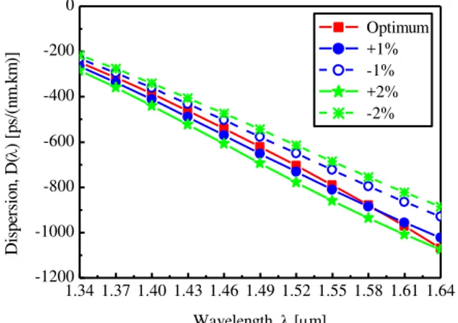
Fig. 3. Dispersion properties of C-PCFμ optimum dispersion and effects of changing pitch Λ keeping all d/constant.
1.34 1.37 1.40 1.43 1.46 1.49 1.52 1.55 1.58 1.61 1.64 -1200 -1000 -800 -600 -400 -200 0 D is p er si o n , D ( ) [p s/ (n m .k m )]
Wavelength, [m]
Optimum +1% -1% +2% -2%
From numerical simulation, it is found that the proposed dispersion compensating C-PCF shows
large negative dispersion coefficient of about -248.65 to -1069 ps/(nm.km) for optimum parameter
values in the wavelength range 1.34-1.64 µm (270 nm band). Fig. 3 shows dispersion accuracy of the
proposed fiber for pitch, Λ along with the optimum dispersion curve while keeping all d/constant.
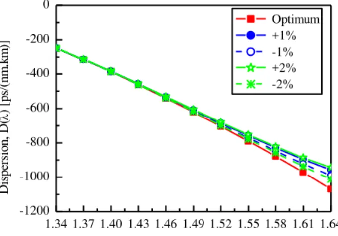
Fig. 4-6 shows the dispersion accuracy of the proposed C-PCF for air hole diameters d1, d2 and d4
along with the optimum dispersion curve. From dispersion properties obtained from Fig. 3-6, it is
clearly shown that the proposed C-PCF maintains the desired dispersion characteristics. It is also
observed that the effect of pitch, and then first air hole diameter, d1 on dispersion properties of the
proposed C-PCF is more significant than other parameters. It is to be mentioned here that d1 largely
controls field confinement and hence dispersion, while the air-hole diameter, d2 controls the
dispersion slope. Fig. 7-10 show the residual dispersion, dispersion slope, relative dispersion slope,
and compensation ratio respectively against wavelength for the proposed five rings C-PCF. Solid line
represents the variation in dispersion properties for optimum parameters. Fig. 7 shows the residual
dispersion after compensating the positive dispersion of 40 km SMF by the proposed C-PCF for
optimum parameters. It is noted that the residual dispersion should be lower than ±64 ps/nm [12] to
compensate for a 40 Gbps signal.
1.34 1.37 1.40 1.43 1.46 1.49 1.52 1.55 1.58 1.61 1.64 -1200
-1000 -800 -600 -400 -200 0
D
is
p
er
si
o
n
,
D
(
)
[p
s/
(n
m
.k
m
)]
Wavelength, [m]
Optimum +1% -1% +2% -2%
Fig. 5. Dispersion properties of C-PCF: optimum dispersion and effects of changing d2.
1.34 1.37 1.40 1.43 1.46 1.49 1.52 1.55 1.58 1.61 1.64 -1200
-1000 -800 -600 -400 -200 0
D
is
p
er
si
o
n
,
D
(
)
[p
s/
(n
m
.k
m
)]
Wavelength, [m]
Optimum +1% -1% +2% -2%
1.34 1.37 1.40 1.43 1.46 1.49 1.52 1.55 1.58 1.61 1.64 -100 -80 -60 -40 -20 0 20 R e si d u a l D is p e rs io n , Dre s [ p s/ n m ]
Wavelength, [m]
=1.00 m
Fig. 7.Variation of residual dispersion against wavelength of 818.4 m long optimized C-PCF to compensate for a 40 km long standard SMFs.
1.34 1.37 1.40 1.43 1.46 1.49 1.52 1.55 1.58 1.61 1.64 -3 -2 -1 0 1 2 3 D is p e rs io n S lo p e ,D S [ p s/ (n m 2 ). k m ]
Wavelength, [m]
=1.00 m
=0.95 m
=0.90 m
=0.85 m
Fig. 8. Spectral variation of dispersion slope for different pitch,.
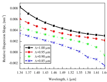
1.34 1.37 1.40 1.43 1.46 1.49 1.52 1.55 1.58 1.61 1.64 -0.002 0.000 0.002 0.004 0.006 0.008 R el at iv e D is p ers io n S lo p e, [ n m -1]
Wavelength, [m]
=1.00 m
=0.95 m
=0.90 m
=0.85 m
Fig. 9. Effect of changing pitch, Ʌ on relative dispersion slope (RDS).
However, the maximum value of residual dispersion in usable bandwidth (1.360-1.625 µm) for the
proposed C-PCF after compensating is about ±62 ps/nm for optimum parameters and particularly at
1.55 µm, it is zero. Thus, it is clearly proved that our proposed C-PCF with optimized parameters is
suitable for systems with high bit rates transmission systems covering entire E to L
1.34 1.37 1.40 1.43 1.46 1.49 1.52 1.55 1.58 1.61 1.64 0.0
0.5 1.0 1.5 2.0
C
o
m
p
en
sa
ti
o
n
R
at
io
Wavelength, [m]
m
m
m
m
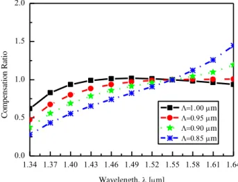
Fig. 10. Compensation ratio as a function of wavelength for the proposed five rings C-PCF with different pitch, Ʌ.
1.34 1.37 1.40 1.43 1.46 1.49 1.52 1.55 1.58 1.61 1.64 1.20
1.21 1.22 1.23 1.24 1.25 1.26 1.27 1.28
E
ff
ec
ti
v
e
R
ef
ra
ct
iv
e
In
d
ex
,
neff
Wavelength, [m] x-polarization y-polarization
Fig. 11. Variation in the effective refractive index for optimized C-PCF for each polarization. (The insets are fundamental
electric field distributions at = 1.55 µm for each polarization for optimum parameters).
-3.25 ps/(nm2.km) over E to L wavelength bands for optimum parameters which shows less
variation in magnitude than [12]. Fig. 9 shows the relative dispersion slope against wavelength and it
is seen that at =1.55 µm, the RDS value of the proposed C-PCF for optimum parameters is
0.0036nm1which perfectly matches to the RDS of SMF. Compensation ratio of the proposed C-PCF
is evaluated as a function of wavelength and best compensation is obtained for the optimum
parameters as shown in Fig. 10. Variation in the effective refractive index for optimized C-PCF for
each polarization is shown in Fig. 11. The fundamental mode of electric field pattern at = 1.55 µm
for each polarization is shown for optimum parameters in the insets of Fig. 11. The proposed C-PCF
also exhibits a birefringence of order 1.64×10⁻⁴.
VI. EFFECTIVE AREA
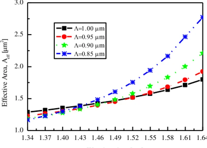
Fig. 12 represents the effective area of the proposed five rings C-PCF at =1.55 µm is 1.574 µm2
for the optimum parameters which is higher than that obtained for eight ring DC-MOF [23] but lower
1.34 1.37 1.40 1.43 1.46 1.49 1.52 1.55 1.58 1.61 1.64 1.0
1.5 2.0 2.5 3.0
E
ff
ec
ti
ve
A
re
a,
Aef
f
[
m
2 ]
Wavelength, [m]
m
m
m
m
Fig. 12. Spectral variation of effective area of the proposed five rings C-PCF for different pitch,.
1.34 1.37 1.40 1.43 1.46 1.49 1.52 1.55 1.58 1.61 1.64
10-8 10-7 10-6 10-5 10-4 10-3 10-2 10-1 100
C
o
n
fi
n
em
en
t
L
o
ss
(d
B
/k
m
)
Wavelength, [m]
=1.00 m
Fig. 13. Confinement loss as a function of wavelength for optimum design parameters and Nr=8.
can be used for interfacing between proposed C-PCF and SMFs successfully [13]. So, we believe
that our proposed C-PCF can be interconnected with SMF without any major complications.
VII. CONFINEMENT LOSS
Fig. 13 describes the wavelength dependence properties of the confinement loss of the proposed
C-PCF. Confinement loss only for optimum parameters is shown. From figure, it is observed that the
confinement loss is about 102dB/km at =1.55 µm considering eight air-hole rings which is the
acceptable level for the transmission fiber. In contrast, confinement loss is not the major concern
because the length of DCF is short compared to transmission fiber. Hence confinement loss will not
be high due to short length of DCF. However 20, 11, 13 and 9 air hole rings are considered by
[25-26,10,12 ] to keep the confinement loss below104dB/m to cover S band [10], C band [25] and
wavelength ranging from 1.46 to 1.64 µm [12, 26]. Therefore the design complexity of the proposed
C-PCF is lower than mentioned above in terms of number of rings used. Finally a comparison is made
between properties of the proposed C-PCF and some other PCFs designed for broadband dispersion
compensation. The comparison between those fibers is presented in terms of magnitude of negative
parameters (NDP) including number of rings in the cladding, Nr, pitches, Ndifferent sized air hole
diameter,Ndin Table 1. Ref. [12] considers two optimum design parameters such as=0.85,
d1/=0.3, d/=0.76 and =0.90, d1/=0.3, d/=0.76 which shows negative dispersion of -230 to
-435 and -190 to - 405 ps/(nm.km) respectively in the wavelength ranging from 1.46-1.64 µm but the
RDS value is 0.0037 and 0.0043nm1. However, negative dispersion of -239.5 and -204.4
ps/(nm.km) are reported at =1.55 µm in [13, 15] respectively. Although Ref. [15] obtains RDS of
0.003543nm1 which is close to SMF's RDS but significant deviation is noticed in Ref. [13]. Ref.
[23] shows accurate RDS value at =1.55 µm but still negative dispersion is not enough. On the other
hand, the proposed C-PCF shows higher negative dispersion value of -790.12 ps/(nm.km) at 1.55 µm
wavelength that is higher that all mentioned in the Table 1 with 100% RDS matching . As a result, the
length of the proposed C-PCF is lower than those presented in Table 1.
TABLE I. COMPARISON BETWEEN PROPERTIES OF THE PROPOSED C-PCF AND OTHER DC-PCF
PCFs Wavelength Band (µm)
ND (ps/nm/km)
ND (ps/nm/km) at λ=1.55 µm
RDS (nm1)
at λ=1.55 µm LDCF (km)
NDP (Nr,N,Nd)
Ref. [12] 1.46-1.64 -230 to -435 -190 to -405
- -
0.003700 0.004300
-
- 9, 1, 2
Ref. [13] 1.53-1.625 -226 to -290 -239.5 0.003000 2.77 6, 1, 2
Ref. [15] 1.35-1.65 - -204.4 0.003543 3.2 5, 1, 3
Ref. [23] 1.40-1.60 -130 to -360 - 0.003600 - 5, 1, 1
C-PCF 1.34-1.64 -248.65 to -1069 -790.12 0.003600 0.82 5, 1, 4
VIII. CONCLUSION
In this study, large negative dispersion properties as well as effective area and confinement loss of
circular photonic crystal fiber have been investigated using FEM. A simple design of circular PCF has
been proposed for dispersion compensation over the entire E to L wavelength band ranging from
1360-1625 nm. It was found that the proposed broadband dispersion compensating C-PCF can be
designed to provide large negative dispersion of about -248.65 to -1069 ps/(nm.km) over E to L
wavelength and an RDS equal to that of SMF's. It is expected that the proposed C-PCF will be greatly
applicable in high-bit-rate optical transmission networks for broadband dispersion compensation.
REFERENCES
[1] B. Zsigri, J. Laegsgaard, and A. Bjarklev, “A novel photonic crystal fiber design for dispersion compensation,” J. Opt.
A: Pure Appl. Opt., vol. 6, no. 7, pp. 717-720, Jul. 2004.
[2] Y. Ni, L. Zhang, L. An, J. Peng, and C. Fan, “Dual-core photonic crystal fiber for dispersion compensation,” Photon.
Technol. Lett., vol. 16, no. 6, pp. 1516-1518, Jun. 2004.
[3] L. P. Shen, W. P. Huang, and S. S. Jian, “Design and optimization of photonic crystal fibers for broad-band dispersion
compensation,” IEEEPhoton. Technol. Lett., vol. 15, no. 4, pp. 540–542, Apr. 2003.
[4] M. Koshiba, and K. Saitoh, “Structural dependence of effective area and mode field diameter for holey fibers,” Opt.
Express, vol. 11, no. 15, pp. 1746–1756, Jul. 2003.
[5] R. R. Musin, and A. M. Zheltikov, “Designing dispersion-compensating photonic-crystal fibers using a genetic algorithm,” Opt. Commun., vol. 281, no. 4, pp. 567-572, Feb. 2008.
[6] G. Ouyang, Y. Xu, and A. Yariv, “Theoretical study on dispersion compensation in air-core Bragg fibers,” Opt.
Express, vol. 10, no. 17, pp. 889-908, Aug. 2002.
[8] J. Laegsgaard, S. E. BarkouLibori, K. Hougaard, J. Riished, T. T. Larsen, and T. Sorensen, “Dispersion properties of photonic crystal fibers-issues and opportunities,”Mater. Res. Soc. Symp. Proc., vol. 797, 2004.
[9] S. G. Li, X. D. Liu, and L. T. Hou, “Numerical study on dispersion compensating property in photonic crystal fibers,”
Acta Phys. Sin., vol. 53, no. 6, pp. 1880-1886, 2004.
[10]S. K. Varshney, T. Fujisawa, K. Saitoh, and M. Koshiba, “Design and analysis of a broadband dispersion compensating photonic crystal fiber Raman amplifier operating in S-band,”Opt. Express, vol. 14, no. 8, pp. 3528-3540, Apr. 2006. [11]S. K. Varshney, N. J. Florous, K. Saitoh, and M. Koshiba, “Numerical investigation and optimization of a photonic
crystal fiber for simultaneous dispersion compensation over S+C+L wavelength bands,”Opt. Commun., vol. 274, no. 1, pp. 74-79, Jun. 2007.
[12]F. Begum, Y. Namihira, S. M. A. Razzak, S. F. Kaijage, N. H. Hai, T. Kinjo, K. Miayagi, N. Zou, “Novel broadband dispersion compensating photonic crystal fibers: Applications in high speed transmission,” Opt. Laser Technol., vol. 41, no. 6, pp. 679-686, Sep. 2009.
[13]S. F. Kaijage, Y. Namihira, N. H. Hai, F. Begum, S. M. A. Razzak, T. Kinjo, K. Miayagi, and N. Zou, “Broadband dispersion compensating octagonal photonic crystal fiber for optical communication applications,” Jpn. J. Appl. Phys., vol. 48, 2009.
[14]M. Chen, Q. Yang, T. Li, M. Chen, and N. He, “New high negative dispersion photonic crystal fiber,” International
Journal for Light and Electron Optics, vol. 121, no. 10, pp. 867-871, Jun. 2010.
[15]N. Ehteshami, and V. Sathi, “A novel broadband dispersion compensating square-lattice photonic crystal fiber,”Opt.
Quant. Electron.,vol. 44, no. 6, pp. 323-335, Jul. 2012.
[16]A. H. Bouk, A. Cucinotta, F. Poli, and S. Selleri, “Dispersion properties of square-lattice photonic crystal fibers,” Opt.
Express, vol. 12, no. 5, pp. 941-946, Mar. 2004.
[17]F. Poli, A. Cucinotta, M. Fuochi, S. Selleri, and L. Vincetti, “Characterization of microstructured optical fibers for
wideband dispersion compensation,” J. Opt. Soc. Amer. A, vol. 20, no. 10, pp. 1958–1962, Oct. 2003.
[18]F. Gerome, J. L. Auguste, and J. M. Blondy, “Design of dispersion compensating fibers based on a dual concentric core photonic crystal fiber,”Opt. Lett., vol. 29, no. 23, pp. 2725-2727, Dec. 2004.
[19]S. G. Yang, Y. J. Zhang, L. N. He, and S. Z. Xie, “Broadband dispersion-compensating photonic crystal fiber,”Opt.
Lett., vol. 31, no. 19, pp. 2830-2832, Oct. 2006.
[20]A. Huttunen, and P. Torma, “Optimization of dual-core and microstructure fiber geometries for dispersion compensation and large mode area,”Opt. Express, vol. 13, no. 2, pp. 627-635, Jan. 2005.
[21]B. P. Pal, and K. Pande, “Optimization of a dual-core dispersion slope compensating fiber for DWDM transmission in the 1480–1610 nm band through G.652 single-mode fibers,” Opt. Commun., vol. 201, no. 4, pp. 335-344, 2002. [22]F. Gerome, J. L. Auguste, S. Fevrier, J. Maury, J. M. Blondy, and L. Gasca, “Dual concentric core dispersion
compensating fiber optimized for WDM application,”Electron Lett., vol. 41, no. 3, pp. 116-117, Feb. 2005.
[23]M. Selim Habib, M. Samiul Habib, S. M. A. Razzak, Y. Namihira, M. A. Hossain, and M. A. G Khan, “Broadband dispersion compensation of conventional single mode fibers using microstructure optical fibers,”International Journal
for Light and Electron Optics, Feb. 2013.
[24]M. A. Hossain, Y. Namihira, M. A. Islam, S. M. A. Razzak, Y. Hirako, K. Miyagi, S. F Kaijage, and H. Higa,
“Tailoring supercontinuum generation using highly nonlinear photonic crystal fiber,”Opt. Laser Technol., vol. 44, no. 6, pp. 1889–1896, Sep. 2012.
[25]T. Fujisawa, K. Saitoh, K. Wada, and M. Koshiba, “Chromatic dispersion profile optimization of dual concentric core
photonic crystal fibers for broadband dispersion compensation,”Opt. Express, vol. 14, no. 2, pp. 893-900, Jan. 2006. [26]Z. Xingtao, Z. Guiyao, L. Shuguang, L. Zhaolun, W. Dongbin, and H. Zhiyun, “Photonic crystal fiber for dispersion