ISSN 0104-6632 Printed in Brazil
www.abeq.org.br/bjche
Vol. 32, No. 01, pp. 139 - 154, January - March, 2015 dx.doi.org/10.1590/0104-6632.20150321s00003129
Brazilian Journal
of Chemical
Engineering
INFLUENCE OF RESIDENCE-TIME
DISTRIBUTION ON A SURFACE-RENEWAL
MODEL OF CONSTANT-PRESSURE
CROSS-FLOW MICROFILTRATION
W. Zhang
1and S. G. Chatterjee
2*1
Department of Civil and Environmental Engineering, 151 Link Hall Syracuse University, Syracuse, New York 13244, USA.
aPresently at 3700 Windmeadows Blvd V228, Gainesville, Florida 32608, USA. 2
Department of Paper and Bioprocess Engineering, SUNY College of Environmental Science and Forestry, 1 Forestry Drive, Syracuse, New York 13210, USA.
Phone: +1-315-470-6517, Fax: +1-315-470-6945 E-mail: [email protected]
(Submitted: November 20, 2013 ; Revised: March 4, 2014 ; Accepted: March 17, 2014)
Abstract -This work examines the influence of the residence-time distribution (RTD) of surface elements on a model of cross-flow microfiltration that has been proposed recently (Hasan et al., 2013). Along with the RTD from the previous work (Case 1), two other RTD functions (Cases 2 and 3) are used to develop theoretical expressions for the permeate-flux decline and cake buildup in the filter as a function of process time. The three different RTDs correspond to three different startup conditions of the filtration process. The analytical expressions for the permeate flux, each of which contains three basic parameters (membrane resistance, specific cake resistance and rate of surface renewal), are fitted to experimental permeate flow rate data in the microfiltration of fermentation broths in laboratory- and pilot-scale units. All three expressions for the permeate flux fit the experimental data fairly well with average root-mean-square errors of 4.6% for Cases 1 and 2, and 4.2% for Case 3, respectively, which points towards the constructive nature of the model — a common feature of theoretical models used in science and engineering.
Keywords: Microfiltration; Residence-time distribution; Surface-renewal model.
INTRODUCTION
Cross-flow membrane filtration technology is widely used in the chemical and biotech industries globally, e.g., in the filtration of parenteral or biologi-cal liquids contaminated with charged particulates, for plasmapheresis, and in wastewater treatment. Depending upon the application, filtration membranes can be polymeric or ceramic. In cross-flow mem-brane filtration, an incoming feed solution or suspen-sion flows across the surface of a membrane and the permeate flow is that portion of the liquid which
passes through the membrane in a direction perpen-dicular to that of the main flow. The permeate flux is affected by the membrane material, liquid velocity, liquid viscosity, type of dissolved/suspended solids and their concentration, transmembrane pressure drop, temperature, and membrane fouling. As time pro-gresses, permeate flow rate declines as the mem-brane fouls due to pore blocking, concentration po-larization and cake-layer buildup.
Koltuniewicz and Noworyta, 1994; Koltuniewicz and Noworyta, 1995; Constenla and Lozano, 1996; Arnot et al., 2000; Chatterjee, 2010; Sarkar et al., 2011; Hasan
et al., 2013). Compared to the film and boundary-layer models of membrane filtration, the surface-renewal model has the potential to more faithfully describe the transfer of dissolved/suspended solids due to random hydrodynamic impulses generated at the membrane surface, e.g., due to membrane rough-ness or by the use of spacers or turbulence promot-ers. Such instabilities, when introduced deliberately into the main flow (e.g., by means of Dean vortices), induce back migration of accumulated solute mole-cules or particulates away from the membrane sur-face and significantly enhance permeation rates (Mallubhotla and Belfort, 1997; Gehlert et al., 1998; Mallubhotla et al., 1998). Almeida et al. (2010) ex-perimentally studied the effect of wall roughness and three different spacer configurations on the micro-flow hydrodynamics of deionized water micro-flowing in slits for a Reynolds number range of 58−500. For five different relative roughness values of the bottom surface of the open channel, the measured longitudi-nal pressure drop departed from the Hagen−Poiseuille formula − increasing with increasing roughness and decreasing slit height. According to these authors, this indicated the presence of surface phenomena in such flows that are irrelevant in macroscale flows. In slits of 1.2 and 1.5 mm height, flow visualization in the longitudinal direction showed the presence of recirculation zones downstream of each spacer fila-ment, whose extent increased as the Reynolds num-ber increased. Above a critical Reynolds numnum-ber in such slits, the flow became unstable, which was re-flected in a change of slope of the Darcy friction factor versus Reynolds number plot. This transition was not observed in a 1-mm high slit, indicating the presence of transient structures in the flow for all values of the studied Reynolds number.
Recently, Hasan et al. (2013) presented a mathe-matical model of cross-flow microfiltration (CFMF) using the surface-renewal concept and classical cake-filtration theory for predicting permeate-flux decline and cake buildup on the membrane surface as a func-tion of process time. The three model parameters Rm
(membrane resistance), kc [a parameter that is related to the specific cake resistance α− see Eq. (3)] and S
(rate of renewal of liquid elements at the membrane surface) were estimated by fitting the model to ex-perimental permeate flow rate data in the CFMF of fermentation broths in laboratory- and pilot-scale units. The parameter S, which is an increasing func-tion of the velocity of the main flow as shown em-pirically by Koltuniewicz (1992), Koltuniewicz and
Noworyta (1994) and Koltuniewicz and Noworyta (1995), can also be looked upon as a “scouring” term, which represents the removal of deposited material from the membrane wall (Arnot et al., 2000) and which depends upon the level of flow instability. In contrast to the well-known critical-flux model of CFMF (intermediate-blocking and cake-filtration cases), the surface-renewal model of Hasan et al. (2013) provides explicit expressions for the permeate flux and cake mass as functions of process time, besides indicating the influence of transmembrane pressure drop, feed concentration and liquid velocity on the permeate flux. Hasan et al. (2013), however, did not empirically test the influence of these vari-ables on the flux and left it for future work. As it currently stands, the surface-renewal model of Hasan
et al. (2013) has no parameter that explicitly indi-cates the fouling regime (unlike the critical-flux model) since it assumes a priori that the primary cause of permeate flux decline is cake accumulation on the membrane surface with pore blocking occur-ring in the initial stages of filtration.
The present paper is a follow-up to the work of Hasan et al. (2013) and examines the influence of the residence-time distribution (RTD) of surface ele-ments on their CFMF model. Along with the RTD from the previous work (Case 1), two other RTD functions (Cases 2 and 3) are used to develop theo-retical expressions for the permeate-flux decline and cake buildup in the filter as a function of process time. The three different RTDs represent three dif-ferent startup conditions of the filtration process. The analytical expressions for the permeate flux are tested by fitting them to the experimental permeate flow rate data that were reported in the earlier work (Hasan et al., 2013).
SURFACE-RENEWAL MODEL OF CROSS-FLOW MICROFILTRATION
In the surface-renewal model of cross-flow mi-crofiltration (Hasan et al., 2013), it is postulated that the primary cause of permeate flux decline is cake accumulation on the membrane surface with the phenomenon of pore blocking occurring in the first moments of filtration, whose effects are included in the membrane resistance Rm (treated as an empirical
suspended solids concentration of cb. With the
pro-gress of time, a cake layer builds up on the surface, causing a gradual reduction of permeate flux with process time until it reaches a steady value. In order to model the microfiltration process, it is assumed that, during the residence time t of a liquid element at the membrane surface, permeate flux and cake accumulation within it can be modeled by classical cake-filtration theory (McCabe et al., 1993). The expression for the permeate or filtrate flux J(t) in a surface element is given by (Hasan et al., 2013):
2 0
1
1 2
c
J t
k t J
(1)
where
0
m
p J
R (2)
and
b
c
c α k
p (3)
In the above, J0 = permeate flux at time t = 0, Δp
= transmembrane pressure drop, µ = viscosity of the filtrate, Rm = resistance of the membrane or filter
me-dium, cb = mass of solids deposited in the filter per
unit volume of filtrate (approximately equal to the feed concentration), and α = specific cake resistance.
We now assume that the dominant flux of sus-pended solids to the membrane wall is that due to the convective motion of the liquid (driven by Δp) com-pared to the solid fluxes to and from the membrane surface due to the surface-renewal mechanism. The mass mc(t) of solids accumulated in the element per
unit area of the membrane surface during the time period of t is then given by (Hasan et al., 2013):
20 0
0
1 2
t b bc b c
c c
c c
m t J t c dt k t
J
k k J (4)
The surface of the membrane at any time tp
dur-ing the filtration process is visualized as bedur-ing populated by a mosaic of liquid elements that have ages that range from zero to tp. If we denote the
age-distribution (i.e., RTD) function of the surface ele-ments as f(t, tp), the age-averaged permeate flux (i.e.,
process flux) Ja(tp) and age-averaged cake mass
accumulated per unit area of the membrane surface
mc,a(tp) at process time tp can be expressed as (Hasan
et al., 2013):
0
,
p
t
a p p
J t J t f t t dt (5)
and
,
0
( )
( ) ( , )p
t
c a p c p
m t m t f t t dt (6)
For later use, we define the following dimen-sionless quantities and also give the definition of the extended Euler gamma function Γ(x, y):
2 0
2
* c
S
S
k J (7)
* p p
t St
(8)
a
0p* * a p
J t J t
J (9)
,
0,
c a p c * *
c a p
b
m t J k m t
c (10)
1Γ ,
x yx y e d (11)
where, as mentioned earlier, S (assumed to be con-stant) is the rate of renewal of liquid elements at the membrane surface.
Based on different speculative hypotheses about the behavior of liquid elements on the membrane wall, which correspond to different startup condi-tions, different RTD functions [i.e., f(t, tp)] can be
derived. These can then be used in Eqs. (5) and (6) to develop expressions for the permeate flux and cake buildup as shown next. Three cases with different RTD functions will be examined.
Case 1
elements flowing into it from the bulk liquid and departing from it to the bulk liquid at a constant rate for tp 0. If S is the surface-renewal rate, the fraction
of the interface that is composed of elements with residence times between t and t + dt at process time
tp is f(t, tp)dt, with f being the RTD function, which is
given by (Koltuniewicz and Noworyta, 1994; Hasan
et al., 2013):
, for 01 p St
p St p
Se
f t t t t e
(12)
As tp, it reduces to the steady-state, famous
age-distribution function, i.e., SeSt, which was originally proposed by Danckwerts (1951). Thus, Eq. (12) is an unsteady-state form of the Danckwerts age-distribution function. The cumulative fraction of surface elements that have ages lying in 0 t tp
can be obtained by integrating Eq. (12) with respect to
t, i.e., the cumulative age-distribution function
, pF t t is given by:
1, for 0
1 p St
p St p
e
F t t t t e
(12A)
Substituting Eqs. (1), (4) and (12) into Eqs. (5) and (6) and integrating yields (Hasan et al., 2013):
1 erf erf * * p S * * * a p t * * * p eJ t πS
e
S t S
(13) and
, 1 3 3Γ , Γ , 1
2 2 * * p S * *
c a p
t * * * * p e m t e S
S S t
(14)
Case 2
The RTD function for this case is another unsteady-state form of the Danckwerts age-distribution func-tion [see Eq. (18)], and has been previously pre-sented by Chung et al. (1971) and Sada et. al. (1979). An elegant derivation of this RTD function,
based on a stochastic population balance of interfa-cial fluid elements, has been provided by Fan et al.
(1993). A derivation of the RTD function, which is based on physical arguments, is presented below for the benefit of the reader.
It is assumed that there are liquid elements, thought of as “blue,” that are already present on the membrane surface (of unit area) at tp= 0 when the
filtration process starts and “red” elements start dis-placing the blue elements by the mechanism of sur-face renewal. At any time tp, the surface will consist
of a mixture of red and blue elements, the population of the latter decreasing as tp increases. Permeate flow
and cake accumulation are assumed to occur in all elements (red and blue) that constitute the mem-brane-liquid interface from tp = 0 onwards. The red
elements will have ages lying within 0 ≤t < tp while
the blue elements will all have ages of exactly tp. At
time tp, the fraction of surface elements that are blue
will be e(Stp), while the other fraction will consist of red elements. Thus, we should have
0
lim , 1
p p
z St p
z t f t t dt e (15)
We now assume that the RTD function of the red elements is given by:
, p St, 0 pf t t Ae t t (16) where A is a constant. Substituting Eq. (16) into Eq. (15) yields:
0
lim 1
p p z St St z tAe dt e (17)
Solving Eq. (17) gives A = S. Therefore, the over-all RTD function is given by:
, 1
for 0
St St
p p p
p
f t t Se u t t δ t t e
t t
(18)
where u(t) and δ( )t are the unit step and delta func-tions, respectively. The cumulative age-distribution function corresponding to Eq. (18) is given by:
1 for 0, 1 at St p p p
e t t
F t t
t t (19)
Equation (19) has a discontinuity at t = tp that
discon-tinuity is due to the fraction of surface elements at process time tp that are blue, which, as mentioned
earlier, is equal to eStp. The age-averaged permeate
flux Ja(tp) can be obtained by substituting Eq. (18)
into Eq. (5), which yields:
0
p p t St Sta p p
J t J t Se dt J t e (20)
The first and the second terms on the right-hand-side of Eq. (20) represent the contributions of the red and blue elements, respectively, to the flux. Substi-tuting Eq. (1) into Eq. (20), integrating and using the dimensionless quantities defined earlier, yields the following expression for the permeate flux:
erf
erf * * p
* * S * * * *
a p p
* t * *
p
J t e πS S t S
S e S t
(21)
Using the RTD given by Eq. (18) in Eq. (6) gives:
, 0
p p t St Stc a p c c p
m t m t Se dt m t e (22)
Utilizing Eqs. (4) and (22) yields the following expression for the cake mass:
, Γ 32, Γ 32, 1
* * p S * * * * *
c a p * p
* * t p *
e
m t S S t
S S t e S (23) Case 3
The age-distribution function for this case is an extension of Case 2. The RTD function is summa-rized in Eq. (24):
1
1 1
for 0 , 0
1 1
, for 0 ,
1 1 for , p p p p St
p p p
St
p p p
t t t
t S
f t t Se t t t
S S
Se t t t t
S S
(24)
The membrane surface is assumed to be initially empty of liquid elements. At tp = 0 when the
filtra-tion process starts, the surface starts filling up with such elements (with no outflow of elements) until a time tpK
S when the surface-renewal mechanism
is triggered and when liquid elements, which enter the interface from the bulk, start displacing those already occupying the membrane wall, which start flowing out of the interface to the bulk liquid. For simplicity (i.e., to avoid introducing an extra pa-rameter), a value of K = 1 is assumed in the devel-opment that follows, which provides a derivation of the RTD function represented by Eq. (24).
During the time interval 0 tp 1
S, the
age-dis-tribution function of the liquid elements at the mem-brane surface (which is filling up with such ele-ments) will be uniform and equal to 1
p
t , i.e.,
0 0
1
, 1
p
pt t
p
p
f t t dt dt
t (25)
When surface renewal starts at tp1
S, let all
liquid elements already occupying the membrane wall at 1
p
t S be imagined to have the color “blue,” while those liquid elements from the bulk that start displacing the blue elements from 1
p
t
S onwards
be thought of as being “red.” A similar situation as that described in Case 2 prevails, i.e., at any time
1
p
t S, the surface will consist of a mixture of red and blue elements with ages lying in the ranges of 0 to 1
p
t S and 1 p
t S to tp, respectively. The RTD
function for the red elements, all of which have ages in 0 t tp 1
S , will be
St
Se while that for the blue
elements, all of which have ages in tp 1 t tp
S ,
will be Se1Stp since
1/ 10 0 1/
, 1
p p
p pp
t t S t
St St
p
t S
f t t dt Se dt Se dt (26)
Hence, equations for the permeate flux and cake mass can be derived depending upon the range in which the process time tp lies. The cumulative
11
for 0 , 0
1 1
1 for 0 ,
,
1
1 ( ) for ,
1 p p p p St p p p St
p p p
p
t
t t t
t S
e t t t
S S
F t t
Se t t t t t S t S (26A)
i) 0 <tp 1 (i.e., 0 <t*p 1)
S
Equation (5) becomes
0 1 ( )
( ) p t a p pJ t J t dt
t (27)
Upon substituting Eq. (1) into Eq. (27), the per-meate-flux expression is found to be:
21 * * * p * *
a p * * p
S t S
J t
t S (28)
The cake mass mc,a(tp) can be obtained from the
following equation:
, 0 1
p t c a p cp
m t m t dt
t (29)
Substituting Eq. (4) into Eq. (29) and integrating yields:
3 2 , 2 1 1 3 * * * p * *c a p * * p
S t S
m t
t S (30)
ii) tp 1(i.e., t*p 1) S
Equation (5) becomes
1/ 1 0 1/
p p p pt S t
St St
a p
t S
J t J t Se dt J t Se dt (31)
Substituting Eq. (1) into Eq. (31) and integrating yields the following equation for the permeate flux:
1 1
2
erf 1 erf
* p * * * * * t p p * * *
a p * *
S * * * * p
S t S t J t S e
S S
e πS S t S
(32)
The cake mass mc,a(tp) is given by the following
equation using the appropriate RTD [i.e., Eq. (24)]:
1/ 1 , 0 1/
p p p pt S t
St St
c a p c c t S
m t m t Se dt m t Se dt (33)
Substituting Eq. (4) into Eq. (33) and integrating yields:
, 3 3 2 2 1 3 3Γ , Γ , 1
2 2 1 2 1 3 * * p S * * * * *
c a p p
*
* * * * t * p p * *
e
m t S S t
S
S t S t
e S
S S
(34)
We note that Eqs. (32) and (34) approach Eqs. (28) and (30), respectively, as t*p1, i.e., the per-meate flux and cake mass are continuous at t*p1.
For all three cases (which use different RTD functions), it may be shown that as t*p 0
0
1* * a p
J t (35)
and
, 0 0
* * c a p
m t (36)
while as t*p
0 0 1 erf * a p* * lim *
a p lim
S * *
J t J
J t J
J J
e πS S
and
, , Γ 32, 1
*
S
* * * *
c a p c lim *
e
m t m S
S
(38)
where Jlim is the value of the limiting or steady-state permeate flux and m*c lim, is the steady-state value of the dimensionless cake mass.
Unlike laboratory or pilot-scale operation, indus-trial membrane filtration systems are generally not allowed to reach steady state. In order to maintain a high level of permeate flux, periodic backwashing is employed so as to regain the permeability of the membrane partially. Szwast et al. (2013) presented an integrated microfiltration model for concentrating a batch suspension in which each cycle consists of a normal period of operation in which the permeate flux declines with time followed by a period of backwashing in order to clean the membrane. Their model can predict the variation of the suspension
concentration, permeate flux and temperature of the suspension with process time.
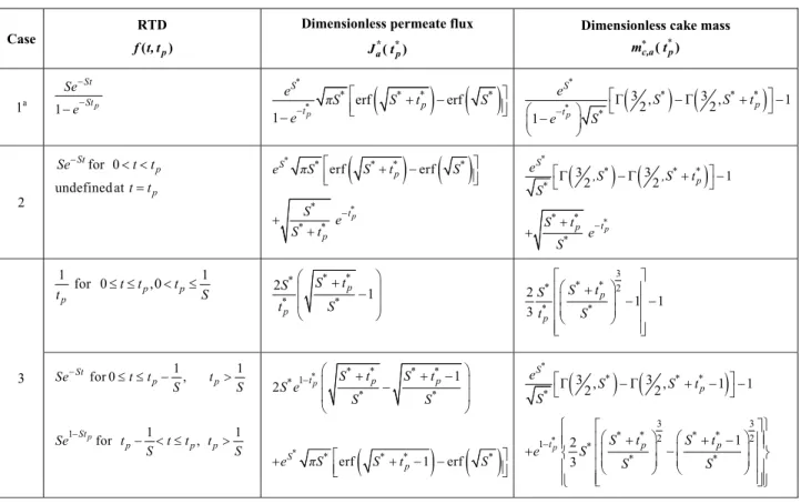
Table 1 presents a summary of the results for the three cases discussed earlier that correspond to the different RTD functions. It can be observed from this table that, in dimensionless coordinates, the permeate flux and cake mass are functions of process time with the surface-renewal rate being the only governing parameter.
The model parameters can be estimated as fol-lows. From the experimental value of Jlim and Eq.
(37), the dimensionless surface-renewal rate S* can be determined, while the membrane resistance Rm
can be calculated from the experimental value of the initial flux J0 and Eq. (2). The surface-renewal rate S
can then be estimated by fitting the permeate-flux expressions [i.e., Eqs. (13) or (21), or (28) and (32)] to experimental transient permeate-flux data so as to minimize the root-mean-square (RMS) deviation between predicted and experimental values of the flux. Finally, the values of kc and α can be obtained
from Eqs. (7) and (3), respectively.
Table 1: Expressions for the dimensionless permeate flux and dimensionless cake mass corresponding to the three different RTD functions.
Case
RTD ( p)
f t, t
Dimensionless permeate flux
* *
( )
a p
J t
Dimensionless cake mass
*
( ) c,a p
m t
1a 1
p St St Se
e erf
erf1 * * p S * * * * p t e π
S S t S
e
3 3
Γ 2, Γ 2, 1
1 * * p S * * * p t * e
S S t
e S 2 for 0 undefined at St p p
Se t t
t t
erf erf * * p
S * * * *
p
* t * *
p
e πS S t S S
e S t
3
3 *
1 2 2 * * p S * * * * * t p * p e ,S ,S S S t e S t 3 1 1
for 0 p,0 p p
t t t
t S 2 1
* * * p * * p S t S t S 3 2 2 1 1 3 * * * p * * p S t S t S 1 1
for 0 ,
St
p p
Se t t t
S S
1 1 1
for ,
Stp
p p p
Se t t t t
S S 1 1 2 * p * * * *
t p p
*
* *
S t S t S e
S S
erf 1 erf
*
S * * * *
p
e πS S t S
3
3
Γ 2, Γ 2, 1 1
* S * * * p * e
S S t
S
3 3
2 2
1 2 1
3 * p * * * *
t * p p
* *
S t S t
e S
S S
a
RESULTS AND DISCUSSION
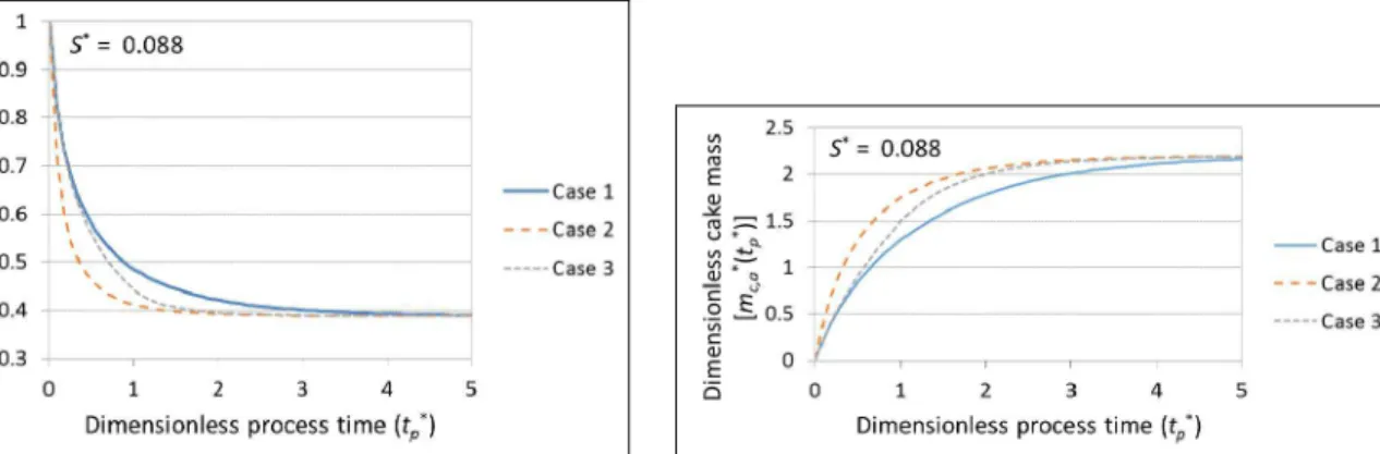
In order to gain theoretical insight, Figures 1-4 show the influence of the surface-renewal rate on permeate-flux decline and cake buildup on the membrane surface as a function of process time in dimensionless coordinates for the three RTD cases discussed previously. In Figure 1 (S* = 0.088), the permeate flux is the greatest for Case 1, lowest for Case 2 and intermediate for Case 3. For all three cases, the permeate flux declines with process time from an initial value of 1 to a limiting value of 0.39, which is a decrease of 61%. The inverse behavior is observed in Figure 2 in which Case 1 has the smallest growth of cake while Case 2 has the greatest, with Case 3 lying in between. For all three cases, the cake mass grows from an initial value of 0 to a steady-state value of 2.19. Increasing the surface-renewal rate S* to 0.353 makes the corresponding curves for permeate flux and cake buildup for the three RTD
cases come closer to one another (Figures 3 and 4) with the limiting permeate flux and cake mass reaching values of 0.60 and 0.85, respectively. Thus, increasing the surface renewal rate by a factor of 4 increases the limiting permeate flux by 54% while decreasing the limiting cakes mass by 61%, which shows the dramatic influence of the surface-renewal rate. From Eqs. (3) and (7) it can be deduced that an increased value of S* implies a higher value of the ratio S/α. It is highly likely that in an actual cross-flow microfiltration run, α would decrease as S
increases, which implies a looser, less compact cake, allowing a greater and easier flow of permeate besides the increased scouring effect due to the surface-renewal mechanism. It should be noted that Hasan et al. (2013) proposed a correlation for the surface-renewal rate S as a function of the liquid velocity in the main flow direction of the membrane channel, channel diameter and roughness, and viscosity and density of the feed suspension.
Figure 1: Behavior of the theoretical permeate
flux as a function of process time in dimensionless coordinates (S* = 0.088).
Figure 2: Behavior of the theoretical cake mass as a function of process time in dimensionless coordinates (S* = 0.088).
Figure 3: Behavior of the theoretical permeate
flux as a function of process time in dimensionless coordinates (S* = 0.353).
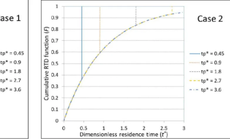
To understand the behavior described in the pre-vious paragraph, Table 2 summarizes expressions for the cumulative age-distribution function F, while Figures 5-7 show them as functions of the dimen-sionless residence time t* (= St) and dimensionless process time tp*(= Stp) for the three RTD cases. For
small values of tp*, the curves of F against t*are quite
different from one another. For example, at tp* = 0.9
and t*= 0.6, the values of F are 0.76, 0.45 and 0.67 for Cases 1, 2 and 3, respectively. Thus, the popula-tion of younger elements at the membrane wall is greatest for Case 1 and smallest for Case 2, with that for Case 3 lying in between. Since younger elements have a higher permeate flux than older elements [see Eq. (1)], the age-averaged permeate flux is greatest for Case 1, followed by those for Cases 3 and 2, respectively (Figures 1 and 3), while cake buildup is smallest for Case 1, greatest for Case 2 and interme-diate for Case 3, respectively (Figures 2 and 4). As
tp* becomes large, the initial state of the membrane
surface becomes more and more unimportant and F
for the three cases approaches the cumulative steady-state age distribution function:
*, *p
1 t*F t t e (39)
In industrial cross-flow microfiltration of fer-mentation broths, the membrane module is often flushed initially with a buffer solution in order to equilibrate it (Ikuta, 2014). There will thus be liquid present on the membrane wall when filtration begins at tp = 0. In such a situation, Case 2 would be more
applicable than Cases 1 and 3. This, of course, does not account for the initial dilution effect of the feed solution due to the presence of the buffer solution in the module, nor does it account for the small time taken to reach the final transmembrane pressure drop, which is gradually raised in order to preserve membrane integrity. The three cases discussed in this paper are therefore highly idealized pictures of a very complex process.
Figure 5: Cumulative residence-time distribution function for Case 1.
Figure 6: Cumulative residence-time distribution function for Case 2.
Figure 7: Cumulative residence-time distribution
Table 2: Cumulative age-distribution functions corresponding to the three different RTD cases.
Case
RTD
* ( * p) F t , t
1
*
*
* * 1
for 0 1
p
t
p t
e
t t e
2
*
* * * *
1 for 0
1 at
t
p p
e t t
t t
3 *
* * *
* for 0 p, 0 p 1 p
t
t t t t
*
*
* * *
1 * * * * *
1 for 0 1, 1
1 p( ) for 1 , 1
t
p p
t
p p p p
e t t t
e t t t t t t
We now turn to the work of Hasan et al. (2013), who performed cross-flow microfiltration experi-ments with fermentation broths in laboratory- and pilot-scale ceramic membrane units, which were conducted in total recycle mode, i.e., both permeate and retentate were continuously recirculated back to the feed vessel. They correlated their experimental permeate flow rate data with Eq. (13) of Case 1 and the reader is referred to their paper for a detailed discussion of the experimental conditions, experi-mental procedures and interpretation of the results. Their paper also compared predictions of the critical-flux model (Field et al., 1995) with their experimen-tal permeate flow rate measurements.
In the current work, whose chief purpose is to ex-amine the influence of the RTD of surface elements on permeate-flux decline and cake buildup, Eq. (21) [Case 2] and Eqs. (28) and (32) [Case 3] are fitted to the experimental data for the transient permeate flow rate of Hasan et al. (2013), a summary of whose experimental runs is provided in Table 3.
Rm of the clean membrane in the small-scale unit
is estimated to be 1.14 × 10¹² and 1.01 × 10¹² m-1 for membrane pore sizes of 0.2 and 0.45 µm, respec-tively, while the main flow velocity in the same unit is estimated to be 1.3 m/s (Hasan et al., 2011). For the cross-flow microfiltration runs, the value of the viscosity of the filtrate necessary to calculate Rm
from Eq. (2) was assumed to be the same as that of water at the experimental temperature (Perry et al., 1984; McCabe et al., 1993), i.e., the effects of sub-strate and salts on the viscosity were neglected.
As mentioned earlier, Hasan et al. (2013) have al-ready presented the results for Case 1; for compari-son purposes, these results are incorporated into the following discussion. Figures 8, 9 and 10 compare predictions of the three variants of the surface-re-newal model with data for the permeate flow rate in the small-scale unit, while Figures 11 and 12 do the same for the pilot-scale unit. By fitting expressions for the permeate flux (Table 1) to these experimental data, optimum values of the three parameters (Rm, kc
and S) were estimated for each case − these are re-ported in Table 4 along with root-mean-square (RMS) deviations between the theoretical and experimental permeate flow rates.
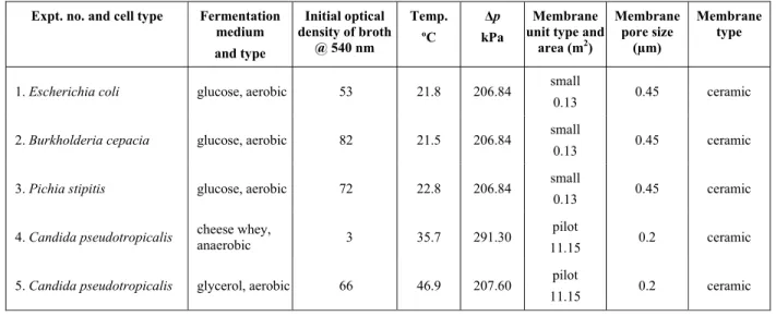
Table 3: Summary of the cross-flow microfiltration experimental runs of Hasan et al. (2013).
Expt. no. and cell type Fermentation medium and type
Initial optical density of broth
@ 540 nm
Temp. ºC
Δp
kPa
Membrane unit type and
area (m2)
Membrane pore size
(µm)
Membrane type
1. Escherichia coli glucose, aerobic 53 21.8 206.84 small
0.13 0.45 ceramic
2. Burkholderia cepacia glucose, aerobic 82 21.5 206.84 small
0.13 0.45 ceramic
3. Pichia stipitis glucose, aerobic 72 22.8 206.84 small
0.13 0.45 ceramic
4. Candida pseudotropicalis cheese whey,
anaerobic 3 35.7 291.30
pilot
11.15 0.2 ceramic
5. Candida pseudotropicalis glycerol, aerobic 66 46.9 207.60 pilot
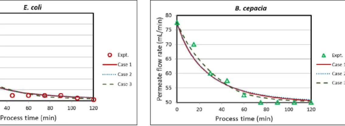
Figure 8: Comparison of theoretical and experi-mental (Hasan et al., 2013) permeate flow rates in the microfiltration of E. coli in the small-scale unit. Values of the model parameters are provided in Table 4 (expt. no. 1).
Figure 9: Comparison of theoretical and experi-mental (Hasan et al., 2013) permeate flow rates in the microfiltration of B. cepacia in the small-scale unit. Values of the model parameters are provided in Table 4 (expt. no. 2).
Figure 10: Comparison of theoretical and
ex-perimental (Hasan et al., 2013) permeate flow rates in the microfiltration of P. stipitis in the small-scale unit. Values of the model parameters are provided in Table 4 (expt. no. 3).
Figure 11: Comparison of theoretical and
ex-perimental (Hasan et al., 2013) permeate flow rates in the microfiltration of C. pseudotropicalis
(grown under anaerobic conditions) in the pilot-scale unit. Values of the model parameters are provided in Table 4 (expt. no. 4).
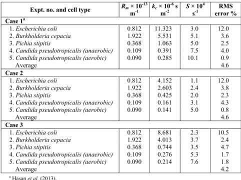
Table 4: Parameter values of the surface-renewal model for the three different RTD cases for the cross-flow microfiltration runs of Table 3.
Expt. no. and cell type Rm × 10
-13
m-1
kc × 10-6 s
m-2
S × 104
s-1
RMS error % Case 1a
1. Escherichia coli 0.812 11.323 3.0 12.0 2. Burkholderia cepacia 1.922 5.531 5.1 3.6 3. Pichia stipitis 0.368 1.063 5.0 2.5 4. Candida pseudotropicalis (anaerobic) 0.109 0.391 7.5 4.0 5. Candida pseudotropicalis (aerobic) 0.090 0.285 10.1 0.9
Average 4.6
Case 2
1. Escherichia coli 0.812 4.152 1.1 12.0 2. Burkholderia cepacia 1.922 2.603 2.4 3.8 3. Pichia stipitis 0.368 0.425 2.0 2.3 4. Candida pseudotropicalis (anaerobic) 0.109 0.161 3.1 4.3 5. Candida pseudotropicalis (aerobic) 0.090 0.141 5.0 0.8
Average 4.6
Case 3
1. Escherichia coli 0.812 8.681 2.3 10.5 2. Burkholderia cepacia 1.922 4.013 3.7 2.4 3. Pichia stipitis 0.368 0.744 3.5 4.7 4. Candida pseudotropicalis (anaerobic) 0.109 0.276 5.3 1.7 5. Candida pseudotropicalis (aerobic) 0.090 0.214 7.6 1.8
Average 4.2
a
Hasan et al. (2013).
The work of Hasan et al. (2013) revealed that the nature of the cake resulting from different types of cells can lead to great differences in the values of Rm
and kc. The higher the values of these two parameters,
the lower is the permeate flux, which can be observed in Figures 8−12. As can be seen from Table 4, in all three cases P. stipitis has the lowest value of kc,
fol-lowed by B. cepacia and E. coli, respectively. For the pilot-scale unit in which microfiltration of the same type of cells (C. pseudotropicalis) grown under an-aerobic and an-aerobic conditions was performed, the values of kc are of comparable magnitude for all the
cases. Rm, which was calculated from the initial flux J0
and Eq. (2) as mentioned earlier, ranges from 0.090– 1.922 1013 m-1, which is about 4 to19 times greater than the value of Rm of the clean membrane for the
small-scale unit. It can also be observed from Table 4 that, for each experimental run, the estimated values of kc and S are of the same order of magnitude for the
three cases. Since the limiting-flux expression is the same for all the cases [i.e., Eq. (37)] from which the value of the dimensionless surface renewal rate S* was calculated, the value of the ratio S/kc should be the
same for a particular run for all three cases [see Eq. (7)], although the individual magnitudes of S and kc
will be different. Thus, for Run 1 (E. coli), S/kc =
0.265 × 10⁻¹⁰ m2/s2 for all the cases.
The experimental permeate flux declines with process time and eventually attains a steady-state value as predicted by theory, which can be seen in
Figures 8−12 where it is also observed that, for all three cases, there is fairly good agreement between the theoretical and experimental permeate flow rates, which suggests that the three variants of the surface-renewal model examined in this work are more or less equivalent as regards the prediction of permeate-flux behavior (with predictions of Cases 1 and 2 being quite close to each other). This fact is corrobo-rated in Table 4, where it is seen that the average RMS deviations between predicted and experimental values of the permeate flow rate are 4.6% for Case 1 and Case 2, and 4.2% for Case 3, respectively.
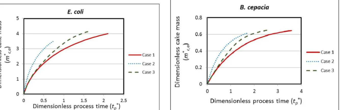
Figures 13−17 exhibit the predicted dimensionless, age-averaged cake mass mc,a* as a function of the
di-mensionless process time tp* in the microfiltration of
different types of cells in the small-scale and pilot-scale units. As the figures show, each curve starts at a value of zero and approaches a steady-state value as the filtration progresses. For a given value of tp*, the
theoretical value of mc,a* is highest for Case 2
fol-lowed by those for Cases 3 and 1, respectively. Since in the work of Hasan et al. (2013) only the optical density at 540 nm of the feed suspension was meas-ured (Table 3) and not the actual cell concentration cb,
it was not possible to calculate values of the cake mass mc,a as a function of the process time tp. For a
Figure 13: Predicted cake buildup with process time in the microfiltration of E. coli in the small-scale unit (S* = 0.025, expt. no. 1).
Figure 14: Predicted cake buildup with process
time in the microfiltration of B. cepacia in the small-scale unit (S* = 0.467, expt. no. 2).
Figure 15: Predicted cake buildup with process
time in the microfiltration of P. stipitis in the small-scale unit (S* = 0.105, expt. no. 3).
Figure 16: Predicted cake buildup with process
time in the microfiltration of C. pseudotropicalis
(grown under anaerobic conditions) in the pilot-scale unit (S* = 0.102, expt. no. 4).
If the dynamic growth of the cake mass could be experimentally measured, comparison of the theo-retical values of the cake mass with the experimen-tally measured ones would be one way of discrimi-nating amongst the three cases examined in this pa-per. It may be thought that another way to discrimi-nate among the cases would be to estimate the sur-face-renewal rate S and specific cake resistance α by independent means, say from hydrodynamic and dead-end filtration measurements, and use these in the permeate-flux expressions of Table 1 to see which one of them is in closest agreement with the experimental flux. Even if such measurements were possible, as discussed earlier, it is very likely that in an actual cross-flow microfiltration run, α would depend strongly upon S, and thus its separate meas-urement would not be meaningful.
CONCLUSIONS
This work examined the influence of the RTD of surface elements on a model of cross-flow microfil-tration that has been proposed recently (Hasan et al., 2013). Along with the RTD from the previous work (Case 1), two other RTD functions were used to de-velop theoretical equations for the permeate flux decline and cake buildup in the filter as a function of process time. The parameters of the model (Rm, kc
and S) were estimated for all three cases by fitting the appropriate expression for the permeate flux to experimental permeate-flow rate data in the micro-filtration of fermentation broths in small- and pilot-scale units, which were reported in the earlier work (Hasan et al., 2013). The higher the values of Rm and
kc, the lower is the permeate flux. P. stipitis had the lowest value of kc, followed by B. cepacia and E.
coli, respectively. For the experimental runs in this work, Rm ranges from 0.090−1.922 10
13 m-1, S
ranges from 3.0−10.1 10-4, 1.1−5.0 10-4 and 2.3−7.6 10-4 s-1,while kc ranges over 0.285–11.323
106, 0.141–4.152 106 and 0.214–8.681 106 s m-2 for Cases 1, 2 and 3, respectively. For all three cases, there is good agreement between the predicted and experimental permeate flow rates with the average RMS deviations between theoretical and experi-mental values being 4.6% for Cases 1 and 2, and 4.2% for Case 3, respectively. The predicted cake mass grows with process time and develops towards a steady-state value.
The three variants of the surface-renewal model examined in this work, all of which have the same three basic parameters (Rm, α and S), are based on
different speculative hypotheses about the behavior of liquid elements on the membrane surface (i.e., the startup condition). From a practical point of view, they can be looked upon as different interpolation schemes for representing the curve of permeate flux as a function of process time, given the initial and long-time or steady-state values of the flux. The fact that all three variants are approximately equivalent as regards prediction of the permeate flux points to the constructive nature of the surface-renewal model – a common feature of the majority of theories or models used in science and engineering (Chatterjee, 2012).
NOMENCLATURE
A constant in Eq. (16) s-1
cb mass of solids deposited in the
filter per unit volume of filtrate (approximately equal to the concentration of solids in the feed or bulk liquid)
kg m-3
f(t, tp) age-distribution function of
liquid elements at the membrane wall
s-1
F(t, tp) cumulative age-distribution
function of liquid elements at the membrane wall
J(t) instantaneous permeate flux in a surface element at time t
m s-1
Ja(tp) age-averaged permeate flux
when the process time is tp
m s-1 ( )
* * a p
J t dimensionless age-averaged permeate flux when the dimensionless process time is
* p
t ; defined by Eq. (9)
Jlim limiting or steady-state
permeate flux
m s-1
* lim
J dimensionless limiting or steady-state permeate flux; Jlim/J0
J0 initial permeate flux m s-1
K constant; assumed equal to 1
kc defined by Eq. (3) s m-2
mc(t) mass of cake in a surface
element per unit area of membrane surface at time t
kg m-2
, ( )
c a p
m t age-averaged cake mass per unit area of membrane surface at process time tp
kg m-2
, ( )
* * c a p
m t dimensionless age-averaged
cake mass when the
dimensionless process time is
* p
,
* c lim
m limiting or steady-state
dimensionless cake mass
Rm hydraulic resistance of the
membrane
m-1
S rate of renewal of liquid elements at the membrane surface
s-1
S* dimensionless surface-renewal rate; defined by Eq. (7)
t residence time of a liquid element at the membrane surface
s
t* dimensionless residence time (= St)
tp process time s
* p
t dimensionless process time
(= Stp)
u(t) unit step function
x parameter of Γ(x, y)
y parameter of Γ(x, y)
z upper limit of the integrals in Eqs. (15) and (17)
s
Greek Symbols
α specific cake resistance m kg-1
Γ(x, y) extended Euler gamma function; defined by Eq. (11) ( )t
delta function
Δp transmembrane pressure drop Pa or kPa variable of integration in
Eq. (11)
viscosity of the permeate kg m-1 s-1
REFERENCES
Almeida, A., Geraldes, V. and Semiao, V., Microflow hydrodynamics in slits: Effects of the walls relative roughness and spacer inter-filaments dis-tance. Chem. Eng. Sci., 65, 3660-3670 (2010). Arnot, T. C., Field, R. W. and Koltuniewicz, A. B.,
Cross-flow and dead-end microfiltration of oily-water emulsions. Part II: Mechanisms and mod-eling of flux decline. J. Membrane Sci., 169, 1-15 (2000).
Chatterjee, S. G., On the use of the surface-renewal concept to describe cross-flow ultrafiltration. In-dian Chemical Engineer, 52, 179-193 (2010). Chatterjee, S. G., The nature of scientific theory.
Current Science, 102, 386-388 (2012).
Chung, B. T. F., Fan, L. T. and Hwang, C. L., Surface renewal and penetration models in the transient state. AIChE J., 17, 154-160 (1971).
Constenla, D. T. and Lozano, J. E., Predicting sta-tionary permeate flux in the ultrafiltration of ap-ple juice. Lebensm. Wiss. U. Technol., 29, 587-592 (1996).
Danckwerts, P. V., Significance of liquid-film coef-ficients in gas absorption. Ind. Eng. Chem. (Eng. and Process Dev.), 43, 1460-1467 (1951). Fan, L. T., Shen, B. C. and Chou, S. T., The
surface-renewal theory of interphase transport: A sto-chastic treatment. Chem. Eng. Sci., 48, 3971-3982 (1993).
Field, R. W., Wu, D., Howell, J. A. and Gupta, B. B., Critical flux concept for microfiltration fouling. J. Membrane Sci., 100, 259-272 (1995).
Gehlert, G., Luque, S. and Belfort, G., Comparison of ultra- and microfiltration in the presence and absence of secondary flow with polysaccharides, proteins, and yeast suspensions. Biotechnol. Prog., 14, 931-942 (1998).
Hasan, A., Yasarla, R., Ramarao, B. V. and Amidon, T. E., Separation of lignocellulosic hydrolyzate components using ceramic microfilters. J. Wood Chem. Technol., 31, 357-383 (2011).
Hasan, A., Peluso, C. R., Hull, T. S., Fieschko, J. and Chatterjee, S. G., A surface-renewal model of cross-flow microfiltration. Brazilian Journal of Chemical Engineering, 30, 167-186 (2013). Ikuta, S., Personal communication (2014).
Koltuniewicz, A., Predicting permeate flux in ul-trafiltration on the basis of surface renewal con-cept. J. Membrane Sci., 68, 107-118 (1992). Koltuniewicz, A. and Noworyta, A., Dynamic
prop-erties of ultrafiltration systems in light of the sur-face renewal theory. Ind. Eng. Chem. Res., 33, 1771-1779 (1994).
Koltuniewicz, A. and Noworyta, A., Method of yield evaluation for pressure-driven membrane proc-esses. Chem. Eng. J., 58, 175-182 (1995).
Mallubhotla, H. and Belfort, G., Flux enhancement during Dean vortex microfiltration. 8. Further di-agnostics. J. Membrane Sci., 125, 75-91 (1997). Mallubhotla, H., Hoffmann, S., Schmidt, M., Vente,
J. and Belfort, G., Flux enhancement during dean vortex tubular membrane nanofiltration. 10. De-sign, construction, and system characterization. J. Membrane Sci., 141, 183-195 (1998).
McGraw-Hill, New York (1993).
Perry, R. H., Green, D. W. and Maloney, J. O., Eds., Perry’s Chemical Engineers’ Handbook. Sixth Ed., McGraw-Hill, New York (1984).
Sada, E., Katoh, S., Yoshii, H. and Ban, Y., Rates of gas absorption with interfacial turbulence caused by micro-stirrers. Can. J. Chem. Eng., 57, 704-706 (1979).
Sarkar, D., Datta, D., Sen, D. and Bhattacharjee, C.,
Simulation of continuous stirred rotating disk-membrane module: An approach based on surface renewal theory. Chem. Eng. Sci., 66, 2554-2567 (2011).