w w w . r b o . o r g . b r
Original
Article
Migration
and
strains
induced
by
different
designs
of
force-closed
stems
for
THA
夽
Sandro
Griza
a,∗,
Luiz
Sérgio
Marcelino
Gomes
b,
André
Cervieri
c,
Telmo
Roberto
Strohaecker
daPost-graduatePrograminMaterialsScienceandEngineering,UniversidadeFederaldeSergipe(UFS),SãoCristóvão,SE,Brazil
bCentrodeEstudosdoServic¸odeCirurgiaeReabilitac¸ãoOrtopédicaeTraumatológica,Batatais,SP,Brazil
cUniversidadeLuteranadoBrasil(Ulbra),Canoas,RS,Brazil
dPost-graduatePrograminMetallurgicalEngineering,deMinasedeMateriais,UniversidadeFederaldoRioGrandedoSul(UFRGS),
PortoAlegre,RS,Brazil
a
r
t
i
c
l
e
i
n
f
o
Articlehistory:
Received20August2014 Accepted6October2014 Availableonline29October2015
Keywords:
Hiparthroplasty Prosthesisdesign Mechanicalphenomena
a
b
s
t
r
a
c
t
Objectives:Subtledifferencesinstemdesigncanresultindifferentmechanicalresponsesof thetotalhiparthroplasty.Testsmeasuringmigrationofthestemrelativetothefemur,as wellasthestrainsinthecementmantleandonthefemurcandetectdifferentmechanical behaviorbetweenstems.
Methods:Inthisarticle,conical,doubleandtripletaperedstemswereimplantedin compos-itefemursandsubjectedtostaticandcyclicloads.Stemsdifferedmainlyontaperangle, calcarradiusandproximalstiffness.Stemmigrationandstrainsonthefemurandinthe cementmantlewereachieved.
Results:Significantdifferences(p<0.05)werenotedinthepermanentrotationbetween dou-bleandtripletapers,inthestrainsontheproximalmedialfemurbetweentripleandboth conicalanddoubletapers,andinthestrainsonthelateralproximalfemurbetweendouble tapersandbothconicalandtripletapers.
Conclusion:Theproposedmechanicaltestswereabletodetectsignificantdifferencesinthe behavioroftheseresemblingstems.Stemproximalstiffnessandthecalcarradiusofthe steminfluenceitsrotationalstabilityandthestraintransmissiontothefemur.
©2015SociedadeBrasileiradeOrtopediaeTraumatologia.PublishedbyElsevierEditora Ltda.Allrightsreserved.
夽
StudydevelopedattheLaboratoryofPhysicalMetallurgy,DepartmentofMetallurgy,Post-GraduatePrograminMetallurgical Engineer-ing,MiningandMaterials,UniversidadeFederaldoRioGrandedoSul(UFRGS),PortoAlegre,RS,Brazil.
∗ Correspondingauthor.
E-mails:[email protected],[email protected](S.Griza).
http://dx.doi.org/10.1016/j.rboe.2015.09.003
Migrac¸ão
e
deformac¸ões
induzidas
por
diferentes
hastes
do
tipo
force-closed
para
ATQ
Palavras-chave:
Artroplastiadequadril Desenhodeprótese Fenômenosmecânicos
r
e
s
u
m
o
Objetivos: Diferenc¸assutis noprojetodahastepodemresultaremdiferentesrespostas mecânicasdaartroplastiatotaldoquadril.Testesquemec¸amamigrac¸ãodahasteem relac¸ãoaofêmur,bemcomoasdeformac¸õesnocimentoenofêmur,podemsalientaras diferenc¸asentrediferentesprojetosdehastes.
Métodos: Neste artigoforamimplantadas hastescônicas, hastesduplamenteafiladase triplamenteafiladasemfêmurescompósitosesubmetidasacargasestáticas ecíclicas. Ashastesdiferenciaram-seprincipalmenteemrelac¸ãoaosafilamentos,aoraiodocalcar eàrigidezproximal.Amigrac¸ãodashasteseasdeformac¸õestantonofêmurquantono cimentoforammedidas.
Resultados: Foramobservadasdiferenc¸as significativas(p<0,05)narotac¸ãopermanente entreashastesduplamenteetriplamenteafiladas,nasdeformac¸õesdonívelproximal medialdofêmurentreashastestriplamenteafiladaseambascônicaseduplamenteafiladas enasdeformac¸õesdonívelproximallateraldofêmurentreashastesduplamenteafiladas eambascônicasetriplamenteafiladas.
Conclusão: Osensaiosmecânicospropostosforamcapazesdeproduzirdiferenc¸as significa-tivasnocomportamentodessashastessemelhantes.Arigidezproximaldahasteeoraio docalcarinfluenciamaestabilidaderotacionaleatransmissãodedeformac¸ãodahasteao femur.
©2015SociedadeBrasileiradeOrtopediaeTraumatologia.PublicadoporElsevier EditoraLtda.Todososdireitosreservados.
Introduction
Polished,collarless,taperedcementedstemsworkasataper locksystem,theso-calledforce-closedbehavior.1Force-closed stemssuchasExeterhavebeenshowingexcellentlong-term results.2Thestemmigratesduetothecementcreep,andit providestheloadtobetransferredthroughoutcementmantle toboneinamorehomogeneousfashion.1,3
Differentsubtledesignchangesoftheforce-closedstems havebeenconceivedinthe lastdecades.Examplesofsuch changesarethedoubletaperedExeterUniversalandthetriple taperedC stems.4 Changes inthe stem shapesuch asthe cross-sectionalandproximalgeometry,anglesandplanesof taperingmayinterferewiththestemstiffnessandstability,as wellaswiththeloadtransmittedtothecementmantleand bone.Alltheseaspectscaninfluencetothepotentialforstem survival.
Mechanicaltestshavebeenpreviouslyproposedto com-parethe mechanicsoftotalhip stems designedwithgreat conceptual differences.5 However, studies of the mechan-ics of the arthroplasty due to subtle differences in shape ofa specific concept as the force-closed stems are scarce. Numericalsimulationwasachievedtopredictthedamageon thecementstrains.6However,mechanicaltestsmonitoring the stem migrationand strainsin the cement mantleand thefemurmayalsocontributetotheunderstanding ofthe mechanicalresponseofsuchaconcept oftotalhip arthro-plasty.
Theobjectiveofthisstudywastodetermineifmechanical testscouldbeabletodetectdifferencesregardingtotheload
transmissionandmigrationofforce-closedstemsthathave subtledesigndifferences.
Materials
and
methods
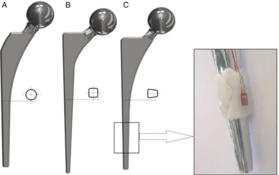
Threegroupsofforce-closedstemsweremanufacturedfrom stainlesssteelASTMFI38andsuppliedbythemanufacturer (MDT Implants,RioClaro,Brazil). Thegroupsdiffered con-cerningthestemshape(Fig.1).Themostrelevantdifferences betweenthestemsareasfollows:stemA,(Spoac®):1◦15′
con-icaldistalshapedesignedtogiveanauto-centralizationwith the medullar cavity;stem B(Maxima®):double-taper (4◦30′
and1◦respectivelyatthelateralandmedialsides,showingin
thefrontalplane,3◦12′atthelateralplane),rectangular
cross-sectionwithroundedcomers;stemC(SpoacNG®):triple-taper
(3◦,3◦30′,3◦53′,respectivelyatthefrontal,lateraland
trans-verseplanes),rectangularcross-sectionwithroundedcomers. Stem Ahasanarrowshoulder.Thetransitionbetweenthe proximal and mediallevel ofthe stemB occursthrough a smallercurvatureradiusofthemedialside(thecalcarradius). Thecalcarradiusofthestems A,Band Care respectively, 120min,40mmand60mm.Therefore,stemBhasthelower proximalstiffness,followedbythestemA.Fourspecimens foreachgroupwereimplantedintwelvelargecompositeleft femurs(3306PacificResearchLabs.)
Fig.1–Thethreeprostheticmodels.Fromlefttoright,theconicalnailA,double-taperednailBandtriple-taperedC-Stem. Thecross-sectionofthenailsisrepresented.Thehighlightedfigureontherightshowsastraingaugefixedatthecement layeronthedistalpartofthenail.Theheadofthenailshasadiameterof28mm.
Cementwasintroducedintothemedullarcavityatretrograde fashionbysyringe.Implantationswereevaluatedalwaysby thesameexperiencedsurgeon(LSMG).
Thedistalportionofthefemurswasattachedtoadevice, thatensuredaposteriorinclinationof9◦ andalateral
incli-nation of 10 degrees, both with respectto the axis ofthe composites(Fig.2).Afterproperpositioningandadequate fix-ation ofthe condyleswith screws,the distal50mmofthe compositeswere soakedbyPMMA.Sampleswere mechan-ically loaded in a servohidraulic machine (MTS 810, MTS Corporation,EdenPrairie,MN,USA).Staticloadswereapplied tothecompositesinthreedifferenttestsituations:(a)onthe headoftheintactfemursbeforeimplantation,(b)onthehead ofthestemafterimplantationand(c)ontheheadofthestem aftercyclicloads.Blocksof10staticloadswereappliedata rateof2300N/min,followedbyoneminuteofload sustain-ingandoneminuteforloadrelieve.Strainanddisplacement variationsduetostaticloadsweretakenasthemeanvalues measuredinthe10staticloads.Thesinusoidalcyclicloadwith
1 2
3
Fig.2–Testapparatusanddisplacementgaugesto measurenailrotation(L1,L2)andaxialmigration(L3).
afrequencyofsevenHzforonemillioncycleswasapplied withintherangeof230and2300N.
Evaluation
method
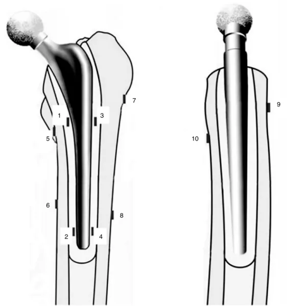
Strains on theouter surface ofthe femurswere measured through sixaxialelectricalresistancestrain-gauges(Kyowa KFG 2-120-C1-11-N15-C02, Tokyo, Japan) at the three test moments.Thestraingaugeswereattainedtothefemursas wellastothecementinasimilarmannerasdescribedina previous protocol.7 Thegaugeswere arrangedinthe direc-tion ofthe femoralaxis. Thepositionsofthe gauges were measuredbyanaltimeter(0.1mmresolution).Strainsinthe cementmantleweremeasuredbyfouraxialelectrical resis-tancestrain-gaugesduringthestaticloadsafterimplantation, and duringthefinalstaticloadsafterthecyclicloads. Dur-ing cyclic loading, strainsin the cement mantlewere also monitoredtoevaluatepermanentdeformations.Bonecement layerswereappliedintheproximalanddistallevelsofeach stem.Cementlayersweresandeduntilathicknessofonemm was achieved,measuredwithacaliper(0.1mmresolution). Thegaugeswereappliedtothecementlayeronthemedialand lateralsides.Fig.1showsastraingaugeattachedtothedistal aspectofastem,priortoimplantation.Table1describesthe positionsofallstraingaugesusedinthisstudy.Fig.3showsthe positionsofthestraingaugesinrelationtoboththecement mantleandthefemur.Thedeformationsweremeasuredwith asignalconditioner(HBMMGCplus,Dannstadt,Germany).To increasedatareliabilityallthestraingaugeswerecalibrated usingaprecisionelectricalresistor.
Table1–Positionofdeformationstraingauges.
Gauge Position
1 Adheredtothemedialaspectofthecement,at130mm ofthenailend
2 Adheredtothemedialaspectofthecement,at20mm ofthenailend
3 Adheredtothelateralaspectofcement,at130mmof thenailend
4 Adheredtothelateralaspectofcement,at20mmofthe nailend
5 Medialaspectoftheoutersurfaceofthefemur,at 63mmofthegreatertrochanterend
6 Medialaspectoftheoutersurfaceofthefemur,at 98mmofthegreatertrochanterend
7 Lateralaspectoftheoutersurfaceofthefemur,at 40mmofthegreatertrochanterend
8 Lateralaspectoftheouterlateralsurfaceofthefemur, at102mmofthegreatertrochanterend
9 Anterioraspectoftheoutersurfaceofthefemur,at 35mmofthegreatertrochanterend
10 Posterioraspectoftheoutersurfaceofthefemur,at 65mmofthegreatertrochanterend
axial migrationand therotationofthe stem.The displace-mentgaugesweresupportedbyanaluminumdeviceattached tothegreatertrochanterthroughboltsandanepoxymantleto ensuregoodstiffnessfixation(Fig.2).Thegaugeusedto mea-sure theaxialmigrationwasattachedtotheuppersurface ofthestemshoulder.Thetransducerstomeasurethe rota-tionwerearrangedseparatelyandat14mmfromeachother, orthogonallyonthefrontsurfaceoftheproximalportionof the stems.Therotation anglewasthencalculated through trigonometricrelations betweenthe difference of displace-mentsmeasuredbythetwotransducersandthedistanceof 14mm.Thus,therotationmeasurementshadaresolutionof 0.16◦.Themigrationswere measured usingasignal
condi-tioner(HBMSpider8,Darmstadt,Germany).Thepermanent migrationsofthestemweremonitoredduringcyclicloading. Theanalysis ofvariance (one-wayANOVA) was usedto detectsignificantdifferencesbetweenthegroupsinalltests (p≤0.05).AccordingtoCristofolinietal.,5atleastthree sam-ples from each group are required to yield a significant differenceinthemeasuredvariables.Thepresentstudyused foursamplesforeachgroup.
3
7
10
9
1
5
6
8
4 2
Table2–Meandeformation(standarddeviation)measurementsincomposites.Thepositions(5-10)weredefinedin Fig.3.
Position Medial5 Medial6 Lateral7 Lateral8 Anterior9 Posterior10
Deformation(m/m) −2249(34) −1378(26) 473(16) 1387(24) −562(14) −852(18)
Results
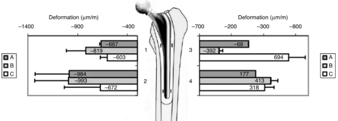
Themeasureddeformationsinintactfemursduringthefirst period of testing are shown in Table 2. The deformations werenegativeonthemedial,anteriorandposterioraspects, whilethe deformationsonthelateral aspectwerepositive. Regardingthecementmantledeformations,negativevalues werefoundonthemedialside(gaugesoneandtwo), with-outsignificantdifferencesbetweenthegroups(Fig.4).Some gaugesinthepositionsthreeandfourweredamagedduring implantationandhinderedthestatisticalanalysisofcement deformationsonthelateralportion.Regardingfemoral defor-mationsafterimplantation,areductionindeformationunder staticloadswasdetected.Theresultswereshownasresidual deformations, that is, the association between the defor-mationsmeasured afterimplantationand those previously measured for each strain gaugein the intact femurs. The triple-taperedC-Stemshowed33%ofresidualdeformationin themedialproximalaspect(gaugefive),withasignificant dif-ferencefromboth,conicalstemA(43%)anddouble-tapered StemB(49%),asshowninFig.5.Intheproximallateralaspect, thedouble-taperedstemBshowed18%ofresidual deforma-tion,withasignificantdifferencefrom bothconicalstemA (27%)andtriple-taperedstemC(36%).
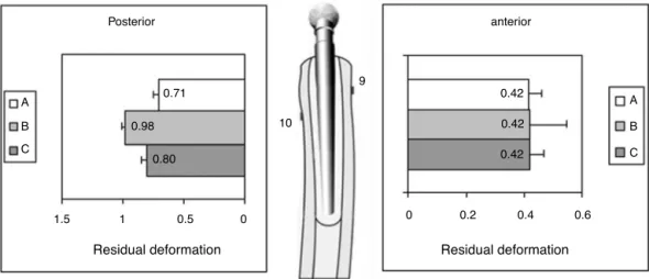
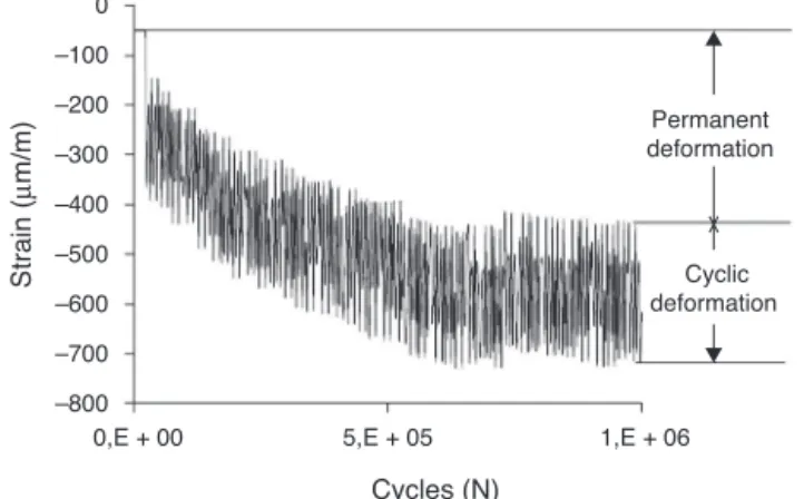
Theinitialdeformationsremainedat42%forallthestems ontheanterioraspect.Asmallerreductionwasfoundonthe posterioraspect,inwhichthedouble-taperedstemBshowed 98%ofresidual deformation, withno significantdifference regardingbothconicalstemA(71%)andtriple-taperedstemC (80%),asshowninFig.6.Bothgaugesembeddedinthecement mantleandthemigrationgaugesshowed,respectively, per-manentdeformationandpermanentmigration,andstabilized between0.2and0.6millioncycles.Therewerenosignificant changesincyclicalamplitude duringthemonitoring. Fig.7
showsthedeformationvariationofgaugetwoinoneofthe stemsCduringcyclicloading.Itispossibletoobservethe per-manentdeformationstabilizingataround0.6millioncycles, whereas the deformation amplitude remained unchanged.
Table3–Axialandrotationalmigrationofthenails. Standarddeviationinparentheses.
Nailmigration NailA NailB C-Stem
Axial(mm) −0.08(0.12) −0.12(0.19) −0.06(0.08) Rotation(degrees) 0.32(0.59) 1.10(0.73) −0.22(0.51)
Nosignificantdifferenceswerefoundinthepermanentaxial migrationofthenails.Thedistalmigration,known as sub-sidence, occurred in the mean interval of0.06mm for the triple-tapered stem C and 0.12mm for the double-tapered stem B (Table 3). There was asignificant difference in the permanentrotationbetweenthedouble-taperedstemBand the triple-tapered stem C,respectively, with 1.1◦ and 0.22◦
(Table 3). Stem rotation generallyoccurred inretroversion. However,thestemCshowedmeanrotationinanteversion.
Discussion
Severalmechanicaltestshavebeenpreviouslypublishedto comparestemdesignsfortotalhiparthroplasty.However,in general,thestudiesaimedatdeformationsorstemmigration measurement.Moreover,previousstudiesgenerallyfocused oncomparingstemswithsignificantdesigndifferences,such as thestudy ofCristofoliniet al.5 that comparedthe stem (LubinusSPII),whichshowedgoodclinicaloutcomes,withthe Müller,curvedstem,whichshowedpoorclinicaloutcomes. Inthisstudy,threeforce-closedstemstypesthathavesubtle designdifferenceswerecompared.Stemmigration,aswellas deformationsinthecementmantleandthefemurwasassesse duringstaticandcyclicloadingconditions.Thesuggestedtest protocolshowedsignificantdifferencesbetweenthestems.
Theanalysesshould beperformedkeeping inmind the useofcompositefemurs,withoutthepresenceofbiological reactions.ThefrequencyofsevenHzappliedinthecyclictests maybeusedwithoutdamagingthebonecementconstitutive properties8andwiththebenefitofshortertimespentduring testing,comparedwithcyclictestsoflowerfrequency.The
A
–1400 –900 –400 –700 –200 –300 –800
694 –392
–68
177 413 318 –667
–819 –603
–984 –993
–672
4 2
3 1
Deformation (µm/m) Deformation (µm/m)
B C
A B C
Medial Lateral
0.43
0.49
0.33
0.27
0.18
0.36
0 0.5
5
6
8 7 A
B
C
A
B
C
Residual deformation
Residual deformation
1
0.67
0.77
0.64
0.63
0.62
0.70
0 A
B
C
A
B
C
1 0.5
Residual deformation
1
0 0.5
1 0.5
Residual deformation
0
Fig.5–Residualdeformationsonthemedialandlateralaspectsofimplantsunderinitialstaticloads.
testswereperformedwithoutthepresenceofmuscleforces. Althoughasudy9 showedthe importanceofmuscleforces appliedtothegreater trochanterforabetterassessmentof thedistributionofstressduetototalhipreplacement,this study was effective in producing significant differences in bothmigration and deformation. While somedeformation gauges in positions three and four were damaged during implantationandhinderedthestatisticalanalysisofcement mantledeformationonlyinthelateralregion,wewereable to compare cement deformations in the medial region of all stems. No significant differences were found between the three stems with respect to cement deformation. The
permanent displacements and deformations measured in our cyclic tests showed a decreasing rate that stabilized between0.2and0.6millioncycles.Theimposedloadonthe cementmantleduringtheinvivoposturesresultsintheflow ofcement.Theflowratedecreaseswithtime(orthecyclic loads),andalthoughitremainsforalongtime,itmaybecome insignificantinthelong-term.10AccordingtoNelissenetal.11 stabilizingthemigrationrateofadouble-taperedstemoccurs withinsixmonthsofinvivouse.Therefore,itispossibleto compareourcyclicloadingwithsuchaperiodofinvivouse.
AccordingtoStolketal.12therotationistheprimarymode ofmigrationinsuchconceptsofforce-closedstemsfortotal
Posterior anterior
A
B
0.71
10
9
0.98
0.80
1.5 1
Residual deformation
0.5 0
0.42
A
B
C 0.42
0.42
0 0.2
Residual deformation
0.4 0.6 C
0
–800
0,E + 00 5,E + 05 1,E + 06 Permanent deformation Cyclic deformation St rain ( µ m/m) Cycles (N) –700 –600 –500 –400 –300 –200 –100
Fig.7–Deformationvariationofgauge2inaC-Stem duringcyclicloading.Thepermanentdeformation stabilizesataround0.6millioncycles,whereasthe deformationamplituderemainsunchanged.
hiparthroplasty.Asignificantdifferenceinpermanent rota-tionwasobservedforthedouble-taperedstemBcomparedto thetriple-taperedstemC.Althoughtherewerenosignificant differencesfortheconicalstemAwhencomparedwiththe othertwo,apermanentrotationashighas1.8◦wasobserved
fort hedouble-tapered stem B.Thisdouble-tapered nail is slimmerthantheothertwo.Ithaslowerproximalstiffness duetothesmallerradiusofthecalcar,whilehavingagreater dimensionalassociationbetweenthedistalandtheproximal lengths.Suchaspectscanincreasethestempotentialfor rota-tion.Thestemrotationcanbeharmfulinthelongtermfor polishedandtaperedstems,sincethepersistenceofrotation overtimecanresultinsmallspacesattheinterfacebetween thestemandthecementmantle.Thesespacescanbe associ-atedwithosteolysisandfrettingproblems.13
Weagreethatthemechanicaltestingprotocolcannotbe usedtodecidethesuccessofanyofthetestedstems mod-elsand,additionally,testscanonlybevalidatedbytheresults ofthelong-termclinicalmonitoringofthestems.However, onecanexpectthat,ifboneresorption-relatedproblemsare detectedinthelong-termclinicalfollow-up,suchproblems willoccur inareasoflowerdeformationtransmittedtothe femur.Afterstemimplantation,thedeformationdecreasewas pronouncedmainlyontheproximalaspectofthefemur, a regionwherethe aseptic looseningismoreevidentafter a long-termclinical follow-up for the Exeter nail,2 an
estab-lishedmodelofforce-closedstem.
Ourresultsforreducingdeformationindifferentpositions (straingauges5–10)showedsignificantreductionintheinitial deformation for the triple-tapered stem C on the medial proximalaspect (gauge5).Thiswas alsothe region where thelowestmeandeformationwasfoundinthecementfort hetriple-taperedC-Stem.Forthe double-taperednailB,we observedamarkedreductionofthedeformationonthe prox-imallateralaspect(gauge7),againaccordingtothetendency to cement deformation ofthis nail (gauge 3).The double-taperedstemBshowedthelowestresidualdeformationon the proximal lateral aspect (18%), but the highestresidual deformationonthe medialproximalaspect(49%),whereas thetriple-taperedstemCshowedtheopposite,i.e.,thelowest
residualdeformationonthemedialproximalaspect(33%)and thehighestontheproximallateralaspect(36%).The double-taperedstemBhasthesmallestcalcarradiusandthelowest proximal stiffness. This causes a higher flexion moment, increasestheloadtransmittedagainstthecalcarandreduces theloadontheproximallateralaspectofthefemur.
Conclusions
Three designs of the force-closed stems were analyzed regarding deformations and migrations. The proposed test protocolwaseffective,asitdemonstratedsignificant differ-ences between the stems. The nails with lower proximal stiffnessshowedlowerrotationalstability.Thenailwiththe smallestcalcarradiusincreasedtheloadtransmittedtothe calcar.
Conflicts
of
interest
Theauthorsdeclarenoconflictsofinterest.
Acknowledgements
Financiador de Estudose Projetos(FINEP), Coordenac¸ão de Aperfeic¸oamentodePessoaldeNívelSuperior(CAPES)e Con-selhoNacionaldeDesenvolvimentoCientíficoeTecnológico (CNPq)andMDTImplantesforprovidingnailsandcomposite femurs.
r
e
f
e
r
e
n
c
e
s
1.NormanTL,ShultzT,NobleG,GruenTA,BlahaJD.Bonecreep andshortandlongtermsubsidenceaftercementedstem totalhiparthroplasty(THA).JBiochem.2013;46(5):949–55.
2.LingRS,CharityJ,LeeAJ,WhitehouseSL,TimperleyAJ,Gie GA.Thelong-termresultsoftheoriginalExeterpolished cementedfemoralcomponent:afollow-upreport.J Arthroplasty.2009;24(4):511–7.
3.EkET,ChoongPF.Comparisonbetweentriple-taperedand double-taperedcementedfemoralstemsintotalhip arthroplasty:aprospectivestudycomparingtheC-Stem versustheExeterUniversalearlyresultsafter5yearsof clinicalexperience.JArthroplasty.2005;20(1):94–100.
4.WroblewskiBM,SineyPD,FlemingPA.Tripletaperpolished cementedstemintotalhiparthroplasty:rationaleforthe design,surgicaltechnique,and7yearsofclinicalexperience. JArthroplasty.2001;168Suppl.1:37–41.
5.CristofoliniL,TeutonicoAS,MontiL,CappelloA,ToniA. Comparativeinvitrostudyonthelongtermperformanceof cementedhipstems:validationofaprotocoltodiscriminate betweengoodandbaddesigns.JBiochem.
2003;36(11):1603–15.
6.NewAM,TaylorM,WroblewskiBM.Effectofhipstemtaper oncementstresses.Orthopedics.2005;28Suppl.8:S857–62.
7.StolkJ,VerdonschotN,CristofoliniL,ToniA,HuiskesR.Finite elementandexperimentalmodelsofcementedhipjoint reconstructionscanproducesimilarboneandcementstrains inpre-clinicaltests.JBiochem.2002;35(4):499–510.
9. VanderPloegB,TaralaM,HommingaJ,JanssenD,BumaP, VerdonschotN.Towardamorerealisticpredictionof peri-prostheticmicromotions.JOrthopRes. 2012;30(7):1147–54.
10.StolkJ,VerdonschotN,MurphyBP,PrendergastPJ,HuiskesR. Finiteelementsimulationofanisotropicdamage
accumulationandcreepinacrylicbonecement.EngFract Mech.2004;71(4–6):513–28.
11.NelissenRG,GarlingEH,ValstarER.Influenceofcement viscosityandcementmantlethicknessonmigrationofthe
Exetertotalhipprosthesis.JArthroplasty.2005;20(4): 521–8.
12.StolkJ,MaherSA,VerdonschotN,PrendergastPJ,HuiskesR. Canfiniteelementmodelsdetectclinicallyinferior cementedhipimplants?ClinOrthopRelatRes. 2003;409:138–50.