J. of the Braz. Soc. of Mech. Sci. & Eng. Copyright 2012 by ABCM April-June 2012, Vol. XXXIV, No. 2 / 179
N. Agung Pambudi [email protected] Semarang State University Mechanical Engineering Department Kampus sekaran, gunungpati 50229 Semarang, Indonesia
Shuichi Torii [email protected] Kumamoto University Mechanical System Engineering 860-8555 Kurokami, Kumamoto, Japan
M. Syamsiro [email protected] Department of Mechanical Engineering
University of Janabadra 55001 Yogyakarta, Indonesia
Harwin Saptoadi [email protected]
Gadjah Mada University Mechanical and Industrial Engineering Grafika No. 2 Kampus UGM 55281 Yogyakarta, Indonesia
Indra Mamad Gandidi [email protected] Department of Mechanical Engineering
University of Janabadra 55001 Yogyakarta, Indonesia
Emission Factor of Single Pellet Cake
Seed Jatropha Curcas in a Fix Bed
Reactor
The objective of this study is to evaluate the emission factor of oil cake seed Jatropha curcas that was formed into pellets with three parameters: pyrolisis, densification and air flow rate. The effect of pyrolisis was investigated using four samples of pellet: non-pyrolysis pellet, 90 minutes non-pyrolysis pellet, 120 minutes non-pyrolysis pellet, 150 minutes pyrolysis pellet. The effect of densification was provided by three samples: 11 mm, 13 mm, and 16 mm diameter. Furthermore, the parameter of air flow rate was varied from 0.1 m/s to 0.4 m/s. The results show that the lowest emission factor occurs in the non-pyrolysis pellet containing 14.3 gram carbon monoxide per kilogram pellet. Meanwhile the best densification was obtained by 13-mm diameter pellet containing 14.8 gram carbon monoxide. Air flow rate of 2.0 m/s was the suitable air flow rate to achieve lowest emission factor.
Keywords: emission factor, pellet, pyrolysis, Jatropha curcas waste, solid fuels, combustion
Introduction1
In the last decades, the development of Jatropha curcas plants has been increasing in trend significantly. Several countries like Asia and Africa as well as South America and Indonesia (Hambali, 2007), Thailand (Kritana et al., 2010), India (Shah et al., 2005), and Nicaragua (Foidl et al., 1996) develop biodiesel from its seed. Studies on a conversion of the plants into biodiesel have been conducted by researchers (Openshaw, 2000; Shah et al., 2005; Giibitz et al., 1999; Banerji et al., 1985; K. Pramanik, 2003). Jatropha curcas waste, such as cake seed, sludge and shell have greatly potential to be converted into a solid fuel (Kumar et al., 2003; Kumar and Namasivayam, 2009; Vyas and Singh, 2007; and Sricharoenchaikul et al.) Lopex et al. (1997) converted its material into biogas through anaerobic digester process (Lopex et al., 1997). As reported by authors (Openshaw et al., 2000; Banerji et al., 1985), the content of cake seeds of Jatropha curcas achieved 61% to 67% per unit weight. Meanwhile the content of Jatropha curcas oil (JCO) was around 33 to 39%. This means that there is a high possibility to extract Jatropha curcas waste to energy both from shell and cake seed.
Combustion is a chemical process to convert solid waste into heat energy. The process includes drying, devolatilization, and char combustion (Borman and Ragland, 1998). In the devolatilization process, CO emission rises to the peak level and gradually decreases until char combustion reactions stop. The products of biomass
combustion consists of carbon dioxide (CO2), water, ash, sulfur
Paper received 11 September 2009. Paper accepted 3 September 2010 Technical Editor: Demetrio Neto
oxide (SO2), carbon monoxide (CO), unburned hydrocarbon
particles, nitrogen oxide (NO2), smoke and soot (Ndiema CKW et
al., 1998). This paper reports the CO emitted from single pellet combustion in a locally fix bed reactor. The parameters analyzed in these experiments are dimension, pyrolysis and air flow rate. The carbon monoxide released in combustion process is the objective of this research. The best pellet material relating with CO released is the lowest emission factor.
Material and Method
In this experiment, cake seed Jatropha curcas waste was used. It was collected from a local bio-diesel factory. The cake seed sample used was in heterogeneous shapes and sizes. This waste still contained residual oil because not all oils can be released by mechanic pressure machine system in factory. The residual oil trapped inside of cake seeds caused agglutination and it caused randomized particles. The residual oil inside of this cake seed also influenced the heating value.
Pyrolysis
Pyrolysis is a chemical decomposition process with heat
energy in absence of oxygen (O2). The temperature of pyrolysis is
around 300- 800°C and releases substances such as carbon
monoxide (CO), carbon dioxide (CO2), methane (CH4), hydrogen
(H2) steam (H2O), and carbon (C). The objective of the pyrolysis
process is to increase the ignition property, reduce smoke, and increase the heating value (Vest, 2003).
Figure 1. Pyrolisis reactor.
In this experiment, Temperature of pyrolysis was maintained at
400oC. The holding time then has varied between 90 and 150
minutes to observe the emission effect.
Heating Value and Proximate Analyses
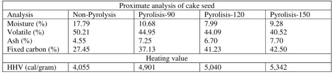
For determining the moisture, volatile matters, and fixed carbon content, the ASTM method was applied in proximate analysis as shown in Table 1. Furthermore, heating value analysis is conducted using a bomb calorimeter with ASTM 2015 method.
Tabel 1 provides a proximate analysis and heating value of cake seed Jatropha curcas with parameter of pyrolysis. It can be observed that increasing a holding time in pyrolysis process increases the content of fixed carbon. It also will decrease the percentage of volatile matter. The logic explanation of this reason is because the long of holding time releases more volatile matter while short of holding time releases uncomplete volatile in particles. The most important aspect of this phenomena is how the holding time generates a better heating value. It can be summarized that increasing the holding time increases the heating value.
Densification
Figure 2 provides the difference of three physical characteristic of densified pellet. A local press machine is used to densify this process.
The pressure applied to this process is 750 kg/cm2. Pellet is made
from a mixture of cake seed Jatropha curcasand a small quantity of
binder. The weight of raw materials used was 1.5 g with variation diameters of pellet: 11, 13 and 16 mm. The result of pellet is shown in Fig. 2, as well as the variation of pellet lengths: 15, 8, 6.5 mm.
Figure 2. Pellets diameter.
Table 1. The result of proximate and heating value analyses.
Proximate analysis of cake seed
Analysis Non-Pyrolysis Pyrolisis-90 Pyrolisis-120 Pyrolisis-150
Moisture (%) Volatile (%) Ash (%) Fixed carbon (%)
17.79 50.21 4.55 27.45
10.68 44.95 7.25 37.13
7.99 44.09 6.70 41.23
9.28 40.52 7.70 42.50 Heating value
HHV (cal/gram) 4,055 4,901 5,040 5,342
Emission Factor
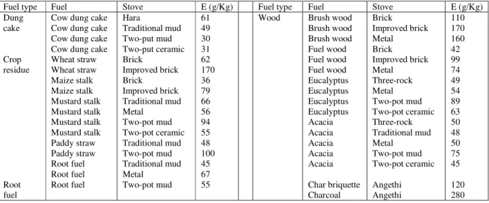
An emission factor is used to measure the emissions’ substance which is released by material activity. Table 2 provides the emission factors of carbon monoxide (CO), which is released during the combustion process from biomass feedstock.
The emission factors presented above use varying feedstock and stove. The lowest emission factor is achieved by cow dung cake using two-put mud stove while the highest emission factors is achieved by charcoal fuels using angethi stove up to 280 g/kg.
Combustion Apparatus
rate; a gas heater (3); a preheat chamber (4) to provide the desirable temperature in the fixed bed combustion chamber (5); a computer (9) and mass balance (10) to analyze the mass reduction from a single pellet. Pellet cup is connected to the mass balance and controls the mass of pellet for each second. Then, the data is stored to the computer automatically. Digital thermocouples (7, 8) measure gas temperature while the gas analyzer (6) measures CO emission. The Weighing unit used for this research is AND from A&D while gas analyzer used Dwyer series 1207. The unit quickly measures and calculates CO emission with high accuracy (±20 ppm < 400 ppm, ±5% > 400 ppm).
J. of the Braz. Soc. of Mech. Sci. & Eng. Copyright 2012 by ABCM April-June 2012, Vol. XXXIV, No. 2 / 181 combustion chamber, pellet cup is prepared which is connected to
electronic mass balance (10). After the steady temperature achieved, pellet enters into combustion chamber. It is located in a
cup. The combustion process is started and the mass of pellet reduces. This information appears in computer (7).
Table 2. Emission factor from biomass combustion (Zhang et al., 1999).
Fuel type Fuel Stove E (g/Kg) Fuel type Fuel Stove E (g/Kg)
Dung cake
Crop residue
Root fuel
Cow dung cake Cow dung cake Cow dung cake Cow dung cake Wheat straw Wheat straw Maize stalk Maize stalk Mustard stalk Mustard stalk Mustard stalk Mustard stalk Paddy straw Paddy straw Root fuel Root fuel Root fuel
Hara
Traditional mud Two-put mud Two-put ceramic Brick
Improved brick Brick
Improved brick Traditional mud Metal
Two-pot mud Two-pot ceramic Traditional mud Two-pot mud Traditional mud Metal
Two-pot mud
61 49 30 31 62 170 36 79 66 56 94 55 48 100 45 67 55
Wood Brush wood
Brush wood Brush wood Fuel wood Fuel wood Fuel wood Eucalyptus Eucalyptus Eucalyptus Eucalyptus Acacia Acacia Acacia Acacia Acacia
Char briquette Charcoal
Brick
Improved brick Metal
Brick
Improved brick Metal
Three-rock Metal Two-pot mud Two-pot ceramic Three-rock Traditional mud Metal
Two-pot mud Two-pot ceramic
Angethi Angethi
110 170 160 42 99 74 49 54 89 63 50 48 50 75 45
120 280
Figure 3. Combustion equipment scheme.
1. Air blower 2. Controller valve 3. Gas heater 4. Preheater chamber 5. Combustion chamber 6. Gas analyser 7. Thermocouple
8. Digital termocouple reader 9. Computer
Result and Discussion
Effect of Pyrolisis
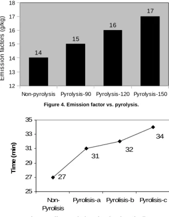
The emission factor is found by integrating the CO emission along a combustion period. From Fig. 4 it can be seen that increasing the holding time increases the emission factor. Therefore, non-pyrolysis pellet releases lowest emission factor. In this stage, non-pyrolysis pellet shows the best solid fuel. To clarify this result emission facto vs. diameter pellet is shown in Fig. 6.
Figure 4. Emission factor vs. pyrolysis.
Figure 5. Effect pyrolysis on burning time of pellets.
It is quite complicated that pyrolysis makes high emission for solid fuel. However, it can be understand that the high emission is caused by burning time. Furthermore, this parameter is influenced by the fixed carbon content. The experiments showed that the fixed carbon contents were 27.45, 37.13, 41.23, 42.50% for non-pyrolysis, pyrolysis 90, pyrolysis 120 and non-pyrolysis, respectively. It can be concluded that increasing the burning time increases the emission, because during the combustion process the material releases its emission.
Effect of Densification
Figure 6 shows the influence of pellet diameter on released emission. In this experiment, air flow used is 0.3 m/s. The
combustion chamber was determined at 400oC. It can be observed
that pellet with diameter of 11 mm showed the lowest emission. Meanwhile highest emission is obtained by pellet with diameter of 13 mm. This phenomena is caused by surface area parameter which is explained by Fig. 7.
Figure 6. Emission factor vs. diameter pellets.
Figure 7. Surface area of pellets.
The surface area per mass (A/m) of pellets determined the emission factor. As we have seen above, a pellet with diameter of 13 mm results the lowest surface area per mass. This is related to the length of combustion process which caused high emission.
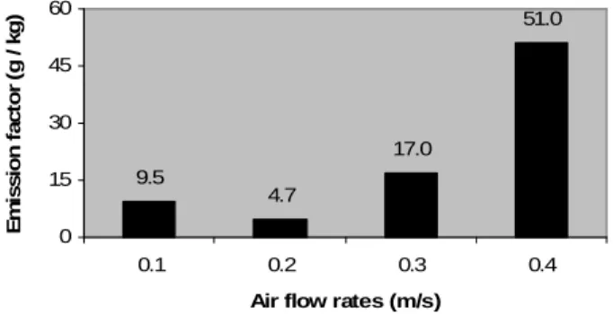
Effect of Air Flow Rate
Figure 8 shows the influence of air flow rate on emission factor. In this experiment, the air flow rates varied from 0.1 m/s to 0.4 m/s. Meanwhile the pellet diameter is determined as 13 mm. It is used non-pyrolysis sample. Temperature of combustion chamber is set at
400oC.
The Air flow rate 0.2 m/s has lowest emission at 4.7 g/kg. Meanwhile the highest emission released occurs at 0.4 m/s air flow rate. Air flow rate is related with supply of oxygen. At air flow rate 0.2 m/s, oxygen supply forms a complete combustion. The air flow rates higher than that influence the increasing of emission. It is because the oxygen is unable to react well with fixed carbon (C) and it causes incomplete combustion process which releases more carbon monoxide (CO). This occurrence can be related to the residence time and thrust of air flow rate. The residence time of carbon monoxide (CO) is too short. It causes incomplete combustion. The other causes are the thrust of air flow rate pushing of carbon monoxide (CO) to exit the chamber before it react with
oxygen (O2) to form carbon dioxide (CO2). Therefore, it only
conducts the partial combustion. 27
34
32 31
25 27 29 31 33 35
Non-Pyrolisis
Pyrolisis-a Pyrolisis-b Pyrolisis-c
T
im
e
(
m
in
)
14.8
17.1
15.2
12 14 16 18
11 13 16
Diameter (mm)
E
m
is
s
io
n
f
a
c
to
r
(g
/
k
g
)
29.3 28.3
43
0 10 20 30 40 50
11 13 16
Diameter (mm)
A
/m
(
m
2/k
g
)
Non-pyrolysis Pyrolysis-90 Pyrolysis-120 Pyrolysis-150 12
13 14 15 16 17 18
14
15
16
17
E
m
is
s
io
n
f
a
c
to
rs
(
g
/k
g
J. of the Braz. Soc. of Mech. Sci. & Eng. Copyright 2012 by ABCM April-June 2012, Vol. XXXIV, No. 2 / 183 Figure 8. Emission factor vs air flow rates.
Conclusion
Based on experimental results, it can be generally found that cake seed Jatropha curcas is a material waste with potential to develop as solid fuel. This potential must be related to the environment effect. Emission factor is used to measure carbon monoxide (CO) which is released by solid fuel combustion. The results show that the best emission factor from varying the pyrolysis is cake seed non-pyrolysis. It releases 14.3 gram carbon monoxide in a kilogram fuel. In densification effect, the lowest emission factor is achieved by pellet with diameter of 13 mm.
The Air flow rate 0.2 m/s has the lowest emission at 4.7 g/kg. At this rate, oxygen supply forms more complete combustion than other rates. It has been indicated that the residence time and the thrust of air flow rates cause this emission.
Acknowledgements
The authors would like to thank Professor Shuichi and Kumamoto University for his assistance during visiting research on his laboratory and its funding.
Reference
Banerji, R., Chowdhury, A.R., Misra, G., Sudarsanam, G., Verma, S.C. and Srivastava, G.S., 1985, “Jatropha Seed Oils For Energy”, Biomass, Vol. 8, pp. 277-282.
Borman, G.L., and Ragland, K.W., 1998, “Combustion Engineering”, McGraw-Hill Book Co., Singapore.
Foidl, N., Foidl, G., Sanchez, M., Mittelbach, M. and Hackel, S., 1996,
“Jatropha curcas l. As a source for the production of biofuel in Nicaragua”,
Bioresource Technology, 96, pp. 77-82.
Giibitz, G.M., Mittelbach, M., Trabi, M., 1999, “Exploitation of the tropical oil seed plant Jatropha curcas L”, Bioresource Technology, Vol. 67, pp. 73-82.
Hambali, E dkk, 2007, “Teknologi Bioenergi”, Agromedia, Jakarta.
Kritana Prueksakorna, Shabbir H. Gheewalaa, Pomthong Malakulb and Sébastien Bonneta, 2010, “Energy analysis of Jatropha plantation systems
for biodiesel production in Thailand”, Energy for Sustainable Development,
14, pp. 1-5.
Kumar Ramakrishnan, Chinnalya Namasivayam, 2009, “Development
and characteristic of activated carbons from Jatropha husk, an agro
industrial solid waste, by chemical activation methods”, Journal Environment Engineering Management Vol.9, pp. 173-178.
Lopex, O., Foidl, G. and Foidl, N., 1997, “Production of Biogas from J. Curcas fruitshell”. In: G.M Gubitz, M. Mittelbach and M. Trabi (Eds).
“Biofuels and Industrial Products from Jatropha curcas”, Dbv-Verlag fur die
Technische Universitat Graz, Graz, Austria, pp. 118-122.
Ndiema, C.K.W., Mpendazoe, Williams, 1998, “Emission of Pollutants from
a Biomass Stove”, Energy Conversion Management, Vol. 39, pp. 1357-1367.
Openshaw, K., 2000, “A review of Jatropha curcas: an oil plant of unfulfilled promise”, Biomass and Bioenergy, Vol. 19, pp. 1-15.
Pramanik, K., 2003, “Properties and use of Jatropha curcas oil and
diesel fuel blends in compression ignition engine”, Renewable Energy, Vol.
28, pp. 239-248.
Senthil Kumar, M., Ramesh, A. and Nagalingam, B., 2003, “An experimental comparison of methods to use methanol and Jatropha oil in a compression ignition engine”, Biomass & Energy, Vol. 25, pp. 309-318.
Shweta Shah, Aparna Sharma, Gupta, M.N., 2005, “Extraction of oil from Jatropha curcas L. seed kernels by Combination of ultrasonication
and aqueous enzymatic oil extraction”, Bioresource Technology, Vol. 96,
pp. 12-123.
Sricharoenchaikul, V., Marukatai, C. and Atong, D., “Fuel Production
from Physic Nut (Jatropha curcas L.) Waste by Fixed-bed Pyrolisis
Process”, Thailand Journal, Vol. 3, pp. 23-25.
Vest, H., 2003, “Small Scale Briquetting and Carbonisation of Organic Residues for Fuel”, Infogate, Eschborn, Germany.
Vyas, D.K., Singh, R.N., 2007, “Feasibility study of Jatropha Seed Husk as an Open Core Gasifier Feedstock”, Renewable Energy, Vol. 32, pp. 512-517.
Zhang, J., Smith, K.R., Uma, R., Ma., Y., Kishore., V.V.N., Lata, K., Khalil, M.A.K., Rasmussen, R.A., Thorneloe, S.T., 1999, “Carbon monoxide
from cookstoves in developing countries: 1. Emission factors”, Chemosphere
Global Change Science, 1, pp. 353-366.
9.5
4.7
17.0
51.0
0 15 30 45 60
0.1 0.2 0.3 0.4
Air flow rates (m/s)
E
m
is
s
io
n
f
a
c
to
r
(g
/
k
g