Abstract — In this paper, we use a novel convoluted geometry to design a dual-band FSS with angular stability and independent polarization operation. The geometry allows the design of a dual-band FSS to block ISM and UNII radio dual-bands. We performed a parametric study with the commercial software ANSYS HFSS. A prototype of our proposed FSS design was built and its transmission characteristics were measured and compared with simulated results. We observed good agreement between numerical and experimental results. The proposed FSS realized a dual-band response at the required bands and it had angular stability and polarization independence.
Index Terms—FSS, Novel Convoluted Geometry, Dual-band Response, ISM, UNII.
I. INTRODUCTION
Frequency Selective Surface (FSS) are often constructed by a periodic array of conducting or
aperture elements deposited in a dielectric layer. The FSS acts as a filter, which rejects some
frequencies. The
frequency response is dependent to incidence angle,
on the polarization of theincident waves, planar geometry of the elements, the spacing between these elements within the array,
and the thickness and permittivity of the substrate [1]. FSS are widely used in different applications
such as spatial filters, radomes, absorbers, reducing radar cross section (RCS), and improving
antennas' parameters [2 - 6].
In past years, an increase has been observed in the use of wireless communication systems,
especially in unlicensed bands, such as ISM (Industrial, Scientific and Medical) and UNII (Unlicensed
National Information Infrastructure) bands. Such increase by concurrent systems has worsened the
interference problem, which not only affects the system performance, but also compromises its own
transmission [7]. The Federal Communications Commission (FCC) established that ISM applications
could occupy three bands. The first starts at 902 MHz and finishes at 928 MHz, second band between
2.4 to 2.5 GHz and the last one of 5.725 to 5.875 GHz. For UNII, the FCC established it at 5.15 to
5.35 GHz and 5.725 to 5.825 GHz.
A Novel Simple Convoluted Geometry to
Design Frequency Selective Surfaces for
Applications at ISM and UNII Bands
Vitor Fernandes Barros, Francisco Carlos G. da Silva Segundo, Antonio Luiz P. S. Campos, Sandro Gonçalves da Silva
Federal University of Rio Grande do Norte, Natal, RN, Brazil e-mails: [email protected]; [email protected]; [email protected];[email protected]
Alfredo Gomes Neto
different systems. The FSS can be placed in walls following a wide variety of arrays, deliberately
filtering out unwanted noise, while allowing certain radio services to pass [7]. In [8], the authors used
convoluted elements to project FSS wallpaper to block unlicensed frequency range of 2.4 GHz, an
ISM radio band. In [9], the authors enhance their previous work and study the stability for both TE
and TM polarized waves not only for normal incident wave but also for oblique incidence angles. In
[10], the authors showed a project of cascading FSS to block the second and third ISM bands and
UNII band. In [11], the authors proposed a compact FSS to reject 5 GHz band with angular stability
for TE and TM modes of polarization. None of those projects blocked all ISM bands and UNII bands
with angular stability and independence of polarization.
In [12], the authors used a fourth-order modified-Hilbert curve to design a single layer FSS for
shielding ISM and UNII simultaneously with stable performance for both vertical and horizontal
polarization under incident angles of 0º through 60º.
In this project we propose an improved array where we used a single layer FSS to block all ISM
and UNII bands and a stability study of polarization wave and incident angle was performed, in a
much simpler design compared to the [12].
II. FSSDESIGN
In the FSS design, a convoluted geometry element was used. In [13], the authors introduced the
word convoluted as a general term to describe geometries of unit cells in FSS arrays where complex
conductor or slot structures twist, turn and in some cases interweave. It is generally known that
convoluted elements produce narrow-bands and can be used at low frequencies due to their greater
electrical length
[14].
In a first step, we initially designed a four-legged loaded FSS [15] with an arm width of 0.5 mm and
a length of 9 mm, as seen in Fig.1(a), along with its dimensions. The white area in Fig. 1(a) represents
apertures, while the black area is conducting patch. The aperture was changed until a value of 3.5 mm
with the aim of resonance frequency being in the band comprising between 5 and 6 GHz. The next
step was to insert a branch in the initial geometry as shown in Fig.1(b).
Fig. 2 illustrates the FSS. The spacing between each branch was 0.5 mm. For the development of
this work, we used the commercial software ANSYS HFSS to perform the numerical analysis of the
transmission properties of the FSS. In the experimental array, we used a low cost dielectric FR-4
substrate with electrical constant permittivity (εr) equal to 4.4, thickness of 1.6 mm and a loss tangent
equal to 0.02. The periodicity in the x and y directions, was 20 mm.
Fig. 3 shows the measured transmission coefficient for a normal incident wave. For each of the five
branch levels (FSS 1 to 5) a new reject band appears. The FSS 5 realizes seven rejection bands. In
FSS 2 we can see two rejection bands that block all ISM and UNII radio bands. We can see that more
stop band means lower attenuation levels. This is because the irradiated energy is distributed in
Fig. 1. Novel convoluted geometry: (a) Level 1 and (b) Level 2.
Fig. 2. Novel convoluted geometry levels 3, 4, and 5
Fig. 3. The frequency response of FSS levels 1, 2, 3, 4, and 5.
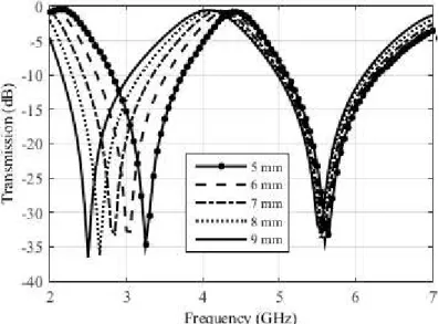
In FSS 2, a study of the influence of the branch length as shown in Fig. 4 was developed. The
Fig. 4. Branch length variation of FSS 2.
Fig. 5 shows the
simulated
transmission coefficient for a normal incident wave in simulatedcases shown in Fig. 4 for branch length changing from 0 to 4 mm. Fig. 6 shows the transmission
coefficient for branch length from 5 to 9 mm.
Fig. 5. Simulated frequency response for branch length from 0 to 4 mm.
In Fig. 5 and 6 we can observe that a changing of the branch length directly affects the first
rejection band reducing its resonance frequency while the second band from 4 mm is little affected.
The increase in branch length causes a distance between the rejection bands.
Increasing the branch
length means an increase in the electrical length and a decrease in the first resonance
frequency and as the second band is not affected, the distance between resonances increases.
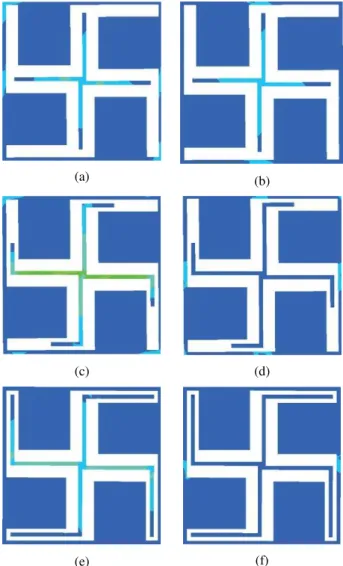
As shown in Fig. 7 a current distribution at each of the resonance frequency for FSS 2 with branch
of 0 mm, 4 mm and 9 mm. We can observe that the second resonance presents low or none variation
in current distribution because of the modification of the branch length, while for the first resonance
we can observe a significant changing in current distribution because of the modification of the
branch length.
(a) (b)
(c) (d)
(e) (f)
Fig. 7. Current distribution: (a) Resonant frequency of 4.8 GHz and (b) Resonant frequency of 6.25 GHz with length of branch of 0 mm; (c) Resonant frequency of 3.55 GHz and (d) Resonant frequency of 5.65 GHz with length of branch of 4
mm; (e) Resonant frequency of 2.5 GHz and (f) Resonant frequency of 5.55 GHz with length of branch of 9 mm.
In Fig. 8 we can see the FSS used to study the tape width in frequency response of FSS. The FSS
Fig. 8. Strip width variation of FSS 2.
In Fig. 9 is shown the frequency response of FSS as a function of the strip width. As observed in
Fig. 9, width influence causes a variation in first resonant frequency. Second band is not affected. So
when increase the width tape, the resonant frequencies tend to come together.
Fig. 9. Simulated frequency response for strip width from 0.5 to 2.5 mm.
III. RESULTS AND DISCUSSIONS
By following, after this parametric analysis, we chose the FSS 2 with branch lengths of 9 mm to
design the desired FSS and we performed an angular stability analysis. Fig. 10 shows the frequency
response of our proposed FSS design for different incident angles and for vertical polarization. Note
that there is no degradation in resonance frequency and bandwidth, which shows that the designed
FSS has angular stability.
As the results in Fig. 11 shows, for horizontal polarization, only incident angles at the 2.5 GHz
band have angular stability. Also, on the other band, there is a reduction of the bandwidth, but it still
contains the UNII band. This behavior can occur because of some adjust in simulations. We fixed a
Fig. 10. Simulated frequency response of our proposed FSS design for different angles of incidence in vertical polarization.
Fig. 11. Simulated frequency response of our proposed FSS design for different angles of incidence in horizontal polarization.
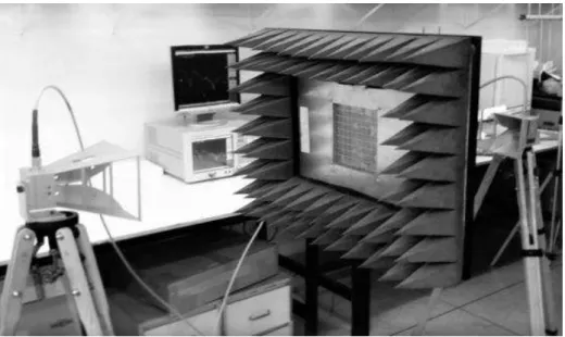
After the simulations, we built a prototype to validate the simulated results. The built prototype is
shown in Fig. 12.
The transmission characteristics of the structures were measured using a network analyzer from
Agilent, model N5230A, and two wideband Vivaldi horn antennas. We analyzed the results obtained
Fig. 12. Fabricated prototype.
Fig. 13. Measurement setup.
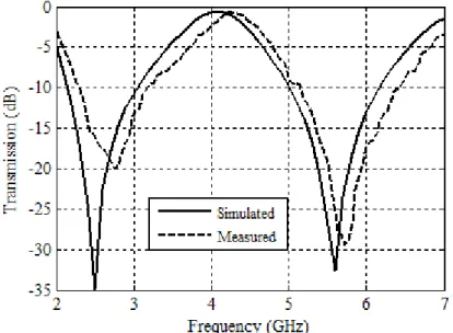
The Fig. 14 presents a good agreement when comparing the simulated and measured results for
normal incidence, presenting a first bandwidth equal to 880 MHz (2.28 3.16 GHz) and a second
bandwidth equal to 1300 MHz (5.14 6.44 GHz), both appropriate to operate in the entire ISM and
Fig. 14. Comparison between measured and simulated results for normal incidence.
Fig. 15 shows the frequency response of our proposed FSS design for different angles of incidence
and vertical polarization. We can note that there is no degradation in resonance frequency and
bandwidth. This fact shows that the designed FSS has angular stability.
Fig. 15. Measured frequency response of our proposed FSS design for different angles of incidence and vertical polarization.
Fig. 16 illustrates the frequency response of our proposed FSS design for different angles of
incidence for horizontal polarization. Again, there is no degradation in bandwidths. This fact shows
that the designed FSS has polarization independence. Different from the simulated results,
Fig. 16. Measured frequency response of designed FSS for different angles of incidence and horizontal polarization.
IV. CONCLUSIONS
In this paper, we used a novel convoluted geometry element to design a FSS with two bands of
resonance, rejecting all ISM and UNII bands. The FSS can be used to limit a radio link or to reduce
interference, allowing systems to continue to operate effectively in the presence of interfering signals.
By building a prototype of a new FSS design and measuring its transmission characteristic, the results
showed that such design provides attenuation levels ranging from 10 to 20 dB at ISM band and from
10 to 30 dB at UNII band. Additionally, our FSS design keeps the simplicity feature in the array, since
it uses only one dielectric layer, that proved to be compact and lightweight, also presenting angular
stability and independence of polarization.
ACKNOWLEDGMENT
The authors express their sincere thanks to the National Council of Research and Development – CNPq for supporting the research work over the project 303693/2014-2.
REFERENCES
[1] Wu, T. K., “Frequency selective surface and grid array”, Jonh Wiley & Sons, New York, E.U.A., 1995. [2] Munk, B. A. Frequency selective surfaces: Theory and design, New York, Wiley, New York, NY, 2000.
[3] Campos, A. L. P. S., Superfícies Seletivas em Frequência – Análise e Projeto (in portuguese), Editora do IFRN, 2010.
[4] Seman, F. C. and Cahill, R., “Frequency Selective Surfaces Based Planar Microwave Absorber”, PIERS Proceedings, Kuala Lumpur, Malaysia, (2012), 906 – 909.
[5] Turpin, J. P., Sieber, P. E., and Werner, D. H., “Absorbing FSS ground plane for reduced-Radar Cross Section of conformal antennas”, Proceedings of Antennas and Propagation Symposium, Orlando, United States, (2013), 464 - 465.
[6] Almeida Filho, V. A. and Campos, A. L. P. S., “Performance optimization of microstrip antenna array using frequency selective
surfaces”, Journal of Microwaves, Optoelectronics and Electromagnetic Applications, Vol. 13, No. 1, (2014), 31 – 46.
[7] Sung, G. H., Sowerby, K. W., Neve, M. J., and Williamson, A. G., “A frequency-selective wall for interference reduction in wireless
indoor environments”, IEEE Antennas and Propagation Magazine, Vol. 48, No. 5, (2006), 29 – 37.
[8] Alkayyali, H. and Qasem, N., “Convoluted Frequency Selective Surface Wallpaper to Block the Industrial, Scientific, and Medical
Radio Bands Inside Buildings”. American Academic & Scholarly Research Journal. Vol. 5, No. 3, (2013).
[9] Kartal, M., Pinar, S. K., Doken, B., and Gungor, I., “A new narrow band frequency selective surface geometry design at unlicensed 2.4
GHz ISM Band”. Microwave and Optical Technology Letters, Vol. 55, No 12, (2013), 2986–2990.
[10] da Silva Segundo, F. C. G. and Campos, A. L. P. S., “Compact Frequency Selective Surface with Dual Band Response for WLAN
Application”. Microwave and Optical Technology Letters, Vol 57, No 2, (2015), 265 - 268.
[11] Rajesh Natarajan, Malathi Kanagasabai, Sanjay Baisakhiya, Ramprabhu Sivasamy, Sandeepkumar Palaniswamy, and Jayaram
Kizhekke Pakkathillam, “A Compact Frequency Selective Surface With Stable Response for WLAN Application”. IEEE Antennas and
[12] Hussain, T., Yang, C., Cao, Q., & Majid, I. “Electromagnetic shielding for WLAN using modified-Hilbert fractals”. In Computational Electromagnetics (ICCEM), 2016 IEEE International Conference on, (2016), (pp. 132-134).
[13] E. A. Parker and A. N. A. El Sheikh, “Convoluted array elements and reduced size unit cells for frequency-selective surfaces,” Proc. Inst. Elect. Eng. Microw., Antennas Propag., vol. 138, pt. H, pp. 19–22, Feb. 1991.
[14] Chuprin, A. D., Parker, E. A. and Batchelor, J. C, “Convoluted double square: single layer FSS with close band spacings,” Electronics Letters, Vol 36, No 22, 1830-1831, 2000.