Abstract— A coplanar waveguide (CPW)-fed patch antenna with triple wideband is presented for simultaneously satisfying Wireless Local Area Network (WLAN) and Worldwide Interoperability for Microwave Access (WiMAX) applications. The proposed antenna mainly consists by three radiating elements: inverted L-shaped Stub1, inverted L-shaped Stub2, and a rectangle Stub3 with a defected ground structure for band broadening. By adjusting the lengths of the three Stubs, three resonant frequencies can be achieved and adjusted separately. The proposed antenna with overall size of only 20×37mm2 explores good triple wideband operation with −10 dB impedance bandwidths of 25.70%, 45.63% and 50.10% at 2.47, 3.20, and 4.92 GHz, respectively, covering the 2.4/5.2/5.8 GHz WLAN and 2.5/3.5/5.5 GHz WiMAX operation bandwidths. This design gives suitable results with a reduction in size and weight and allows integration in handheld devices. Furthermore, nearly omnidirectional radiation patterns over the operating bands have been obtained.
Index Terms— Coplanar waveguide (CPW) feed, Defected ground structure (DGS), Patch antenna, Triple-band antenna, Wideband antenna, WLAN/WiMAX applications.
I. INTRODUCTION
In modern wireless communication systems, multiband antenna plays a very important role for
wireless service requirements [1, 2]. Wireless Local Area Network (WLAN) standards of 2.400-2.484
GHz (IEEE 802.11b / g) / 5.15–5.35 GHz / 5.725–5.825 GHz (IEEE 802.11a) and Worldwide
Interoperability for Microwave Access (WiMAX) standards of 2.5–2.69 GHz / 3.4–3.69 GHz / 5.25–
5.85 GHz are extensively applied in mobile devices such as handheld computers and intelligent
phones (4G smartphones). Many researchers pay lots of attention to designing antennas covering all
frequency bands with characteristics of simple multiband, low-profile, compact size and
omnidirectional pattern for multi-service systems, especially for WLAN and WiMAX applications in
wireless communication systems [3]. Furthermore, it is desirable to be able to control the antenna
bandwidth over different frequency bands individually [4, 5].
There are various reported antenna designs for wireless systems, but the most are single-band or
dual-band [6-18]. A microstrip fed monopole patch antenna with three stubs for dual-band WLAN
Miniaturized Triple Wideband CPW-Fed
Patch Antenna With a Defected Ground
Structure for WLAN/WiMAX Applications
Ahmed Zakaria Manouare1, Saida Ibnyaich2, Abdelaziz EL Idrissi1, Abdelilah Ghammaz1 1
Department of Physics, Laboratory of Electric Systems and Telecommunications (LEST), Faculty of Sciences and Technologies, Cadi Ayyad University, Marrakesh, Morocco.
applications is depicted in [15]. In [19], a simple miniaturized triple-band antenna is realized by using
a defected ground plane for WLAN/WiMAX applications. Double L-slot microstrip patch antenna
array for WiMAX and WLAN applications is proposed in [20]. A coplanar waveguide (CPW)-fed
planar monopole antenna with Y-shaped for PCS / WLAN applications and a compact dual-band
planar antenna for DCS-1900 / PCS / PHS, WCDMA / IMT-2000 and WLAN applications are
presented in [21, 22]. In [23], a compact antenna with a wide square slot in the center, a rectangular
feeding strip and two pairs of planar inverted L strips connecting with the slotted ground for
WLAN / WiMAX applications.
In [24], a triple band monopole antenna for WLAN/WiMAX applications is obtained; the radiator
of the antenna is designed on a 40(W) × 40(L) mm2 substrate and the radiator is composed of three
elements, two branches and a short stub. In [25], a dual-wideband symmetrical G-shaped slotted
monopole antenna is designed for WLAN / WiMAX applications. In [26], a dual wideband coplanar
waveguide-fed notched antenna with two asymmetrical ground planes for multi-band wireless
application has been reported. Further, in [27], a dual wideband printed monopole antenna has been
designed to cover WLAN and WiMAX frequency bands. In [28], the rectangular patch is the main
radiating element of the triple-band antenna combined with split-ring slot enclosed inside of it for
WLAN / WiMAX applications is presented. However, the aforementioned techniques supporting
triple/multi-band operations still suffer from large overall size or a complicated structure [29, 30]. In
[31], a square-slot antenna with symmetrical L-strips is presented for WLAN and WiMAX
applications, but the three resonant frequencies cannot be tuned independently.
In this paper, a simple miniaturized triple wideband patch antenna with a defected ground structure
for WLAN and WiMAX applications is proposed, which is fed by a coplanar waveguide (CPW). The
antenna is created by three Stubs and three resonant frequencies can be obtained and tuned
individually. Simulated results show that the three operation bandwidths of the proposed antenna are
635 MHz, 1460 MHz and 2465 MHz, respectively, which satisfy the required bandwidth of the
2.4 / 5.2 / 5.8 GHz (WLAN) and 2.5 / 3.5 / 5.5 GHz (WiMAX) with an S11 less than -10 dB. Details of
the antenna design and the effects of the key structure parameters on the antenna performances are
neatly examined and discussed.
II. ANTENNADESIGN
The geometry of the proposed triple-band antenna is illustrated in Fig. 1. The antenna substrate is a
Rogers 4350 (thickness H = 0.508 mm, relative permittivity εr = 3.66 and dielectric loss tangent of
0.004). The dimension of the substrate is 20×37 mm2.
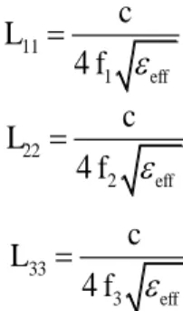
In the geometry, the resonant path length L11 (L1 + W1 + G + Ls1), L22 (L1 + W1 + G + Ls2) and L33 (L1 + G + Ls3) of the three Stubs are set close to quarter-wavelength at their fundamental resonant
(1)
(2)
(3)
The effective permittivity is given approximately by [33]:
1 *
tanh 0.775 ln 1.75 0.04 0.7 0.01 1 0.1 0.25 2
r
eff r
H k g
k k
g H
(4)
where
g W
W k
f f
2
(5)
Where c is the speed of light, Wƒ
is the conductor width,
ε
ris the relative permittivity,
His the
substrate thickness
, εeff is the effective permittivity; ƒ1, ƒ2 and ƒ3 denote the fundamental resonantfrequencies of the Stub1, Stub2 and Stub3 respectively. The planar antenna is fed by a 50Ω
impedance CPW that has a central strip having as width Wƒ = 1.55 mm and the gap between the
central feed line and the ground is fixed at g = 0.3 mm. The proposed antenna was excited by a Wave
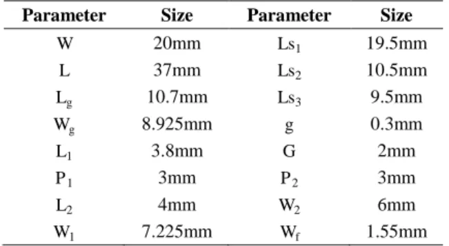
Port with a width WCPW = 10 mm and a height hCPW = 5 mm. For detailed design, all parameters of the
proposed antenna are optimized using the software package High Frequency Structure Simulator
(HFSS) which is based on the Finite Element Method (FEM) and are shown in Table I.
Fig. 1. Geometry of the proposed antenna with defected ground structure (units: mm). 11
1
4
effc
L
f
22 2
4
effc
L
f
33 3
4
effc
L
f
TABLE I.THE SIZE OF PARAMETERS OF THE PROPOSED ANTENNA
Parameter Size Parameter Size
W 20mm Ls1 19.5mm
L 37mm Ls2 10.5mm
Lg 10.7mm Ls3 9.5mm
Wg 8.925mm g 0.3mm
L1 3.8mm G 2mm
P1 3mm P2 3mm
L2 4mm W2 6mm
W1 7.225mm Wf 1.55mm
The simulated reflection coefficient is presented for the optimized set of antenna parameters in Fig. 2.
From the simulated result, it is apparent that a single antenna having three multiple resonant frequencies
with a wide bandwidth is obtained. The simulated impedance bandwidths for S11
−10 dB are about 635MHz for the first band (2.085 GHz to 2.72 GHz), 1460 MHz for the second band (2.89 GHz to 4.35 GHz),
and 2465 MHz for the third band (4.59 to 7.055 GHz). The proposed antenna has a broader bandwidth
covering the required bandwidths of the IEEE 802.11 WLAN standards of 2.4 GHz (2.4 - 2.484 GHz), 5.2
GHz (5.15 - 5.35 GHz), and 5.8 GHz (5.725 - 5.825 GHz); WiMAX standards in the bands at 2.5 GHz
(2.5 - 2.69 GHz), 3.5 GHz (3.4 - 3.69 GHz) and 5.5 GHz (5.25 - 5.85 GHz).
1 2 3 4 5 6 7 8
-50 -45 -40 -35 -30 -25 -20 -15 -10 -5 0
Frequency (GHz)
R
e
fl
e
c
ti
o
n
c
o
e
ff
ic
ie
n
t
(d
B
)
2.72 GHz 2.085 GHz
2.89 GHz
4.35 GHz
4.59 GHz
7.055 GHz
Fig. 2. Simulated result of the reflection coefficient against frequency for the proposed antenna.
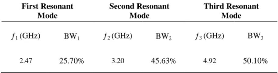
Table II shows the values of resonant frequencies and bandwidths at 10 dB of the three resonant
modes. For the first resonant mode, the resonant frequency is about 2.47 GHz (S11 = 13.25 dB), the
second resonant frequency for the second mode is about 3.20 GHz (S11 = 41.85 dB), and the third
resonant frequency is about 4.92 GHz (S11 = 48.11 dB).
It is worth mentioning that the configuration of the ground plane also affects the characteristics of
impedance performance and broadening the bandwidth especially for the second and the third
operating bands. In fact, ground plane has been useful to design multiband handset antennas [34-36].
TABLE II.SIMULATED IMPEDANCE BANDWIDTHS OF THE PROPOSED ANTENNA
First Resonant Mode
Second Resonant Mode
Third Resonant Mode
ƒ1 (GHz) BW1 ƒ2 (GHz) BW2 ƒ3 (GHz) BW3
2.47 25.70% 3.20 45.63% 4.92 50.10%
III. PARAMETRICSTUDY
A. The Ls1 Variation Effects
The effects of the length of the first stub (Stub1) on the antenna performance are plotted in Fig. 3.
This figure shows the simulated reflection coefficients when the length of Ls1 changes. By adjusting
the length of Ls1, the total length of Stub1 varies. It is seen that the increase in Ls1 decreases the
resonant frequency of the first band and vice versa, while other resonant frequency bands are slightly
affected.
B. The Ls2 Variation Effects
Fig. 4 shows the simulation of the reflection coefficients with variation of Ls2 (Stub2). By tuning
the length of Ls2 from 9.5 mm to 12.5 mm, it is clear that the raise in Ls2 decreases the resonant
frequency of the second band. The third band shifts to higher frequencies as Ls2 is increasing, which is
possibly due to the changing coupling between the two inverted L-shaped. The first band is not
affected.
C. The Ls3 Variation Effects
Varying the length Ls3 of Stub3 to be 8.5, 9.5, 10.5 and 11.5 mm, it can be seen from Fig. 5, Tables
III and IV that with the increasing of length Ls3, the third band shifts towards the lower frequency
1 2 3 4 5 6 7 8 -65 -60 -55 -50 -45 -40 -35 -30 -25 -20 -15 -10 -5 0 Frequency (GHz) R e fl e c ti o n c o e ff ic ie n t (d B )
Fig. 3. Simulated reflection coefficients for different values of Ls1.
1 2 3 4 5 6 7 8
-50 -45 -40 -35 -30 -25 -20 -15 -10 -5 0 Frequency (GHz) R e fl e c ti o n c o e ff ic ie n t (d B )
Fig. 4. Simulated reflection coefficients for different values of Ls2.
1 2 3 4 5 6 7 8
-50 -45 -40 -35 -30 -25 -20 -15 -10 -5 0 Frequency (GHz) R e fl e c ti o n c o e ff ic ie n t (d B )
Fig. 5. Simulated reflection coefficients for different values of Ls3.
TABLE III.THE VALUES OF RESONANT FREQUENCIES OF THE PROPOSED ANTENNA FOR DIFFERENT VALUES OF LS3
Ls3 8.5 mm 9.5 mm 10.5 mm 11.5 mm
ƒ1(GHz) 2.47 2.47 2.47 2.43
ƒ2(GHz) 3.20 3.20 3.20 3.13
ƒ3(GHz) 5.30 4.92 4.53 4.01
TABLE IV.THE VALUES OF BANDWIDTH OF THE THIRD BAND FOR DIFFERENT VALUES OF LS3
Ls3 8.5 mm 9.5 mm 10.5 mm 11.5 mm
Third Band (GHz)
4.87-7.13 (2.260)
4.59-7.055 (2.465)
4.33-7.12 (2.790)
3.93-7.15 (3.220)
D. The Effects of the Defected Ground Structure (DGS) on the Antenna Performance
To demonstrate the effect of the square and rectangular truncation on the ground plane, Fig. 6(a)
and Fig. 6(b) show the different evolution of the geometry of the two ground planes with and without
truncation and its corresponding simulated reflection coefficients. We remark from Table V and Fig.
6(b) that the first truncation (P1, P2) influences on the impedance matching of the second band
(WiMAX) and the reflection coefficient is enhanced from -21.5 dB to -37.24 dB. Furthermore, the
second truncation (W2, L2) affects the upper band; the reflection coefficient is enhanced from -30.68
dB to -39.69 dB. For the proposed antenna, more amelioration of the reflection coefficient and the
bandwidth were registered for second and third resonant band. The change of ground structure has
small effects on the first band.
TABLE V.THE VALUES OF REFLECTION COEFFICIENTS FOR DIFFERENT GEOMETRY OF THE TWO GROUND PLANES
DGS Without Square Rectangular Both S11 (dB)
(Second Band) -21.50 -37.24 -22.62 -41.85 S11 (dB)
(Third Band) -30.68 -28.50 -39.69 -48.11
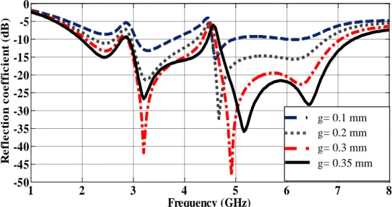
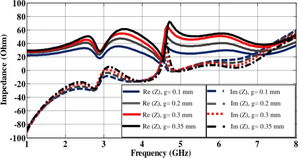
E. The Gap Variation Effects on the Impedance Matching Performance of the Antenna
An important feature of the proposed antenna is the capability of impedance matching at three
operating frequencies using a single CPW feed line. For this, the coupling effect between the feed line
and the two ground planes is investigated. Fig. 7 shows the simulated reflection coefficient for the
proposed antenna with different gap width (g) of 0.1, 0.2, 0.3 and 0.35 mm. As seen in figures 7 and
8, the gap width has a significant effect on the impedance matching performance of the proposed
antenna for the three resonant frequencies.
matching condition for the three operating bands can be optimized with g equal to 0.3 mm.
Without truncation Square truncation Rectangular truncation Proposed antenna (a)
1 2 3 4 5 6 7 8
-50 -45 -40 -35 -30 -25 -20 -15 -10 -5 0 Frequency (GHz) R e fl e c ti o n c o e ff ic ie n t (d B ) (b)
Fig. 6. (a) Design evolution of the geometry of the two ground planes (b) Simulated reflection coefficients for different
geometry of the two ground planes.
1
2
3
4
5
6
7
8
-50
-45
-40
-35
-30
-25
-20
-15
-10
-5
0
Frequency (GHz)
R e fl e c ti o n c o e ff ic ie n t (d B )Fig. 7. Simulated reflection coefficients for the proposed antenna with various gap distance g.
1
2
3
4
5
6
7
8
-100
-80
-60
-40
-20
0
20
40
60
80
100
Frequency (GHz)
Im p e d a n c e ( O h m )Fig. 8. Real part and imaginary part of the impedance of the proposed antenna with various gap distance g.
F. The L1 Variation Effects
As shown in Fig. 9, L1 (the gap between the radiating patch and the two ground planes) could
disturb the performance of the second and the third band antenna but the first band is not affected. It is
evident that the reflection coefficient of the proposed antenna with L1 = 3.8 mm is better than that
L1 = 4.3 mm and L1 = 4.8 mm.
1 2 3 4 5 6 7 8
-50 -45 -40 -35 -30 -25 -20 -15 -10 -5 0 Frequency (GHz) R e fl e c ti o n c o e ff ic ie n t (d B )
Fig. 9. Simulated reflection coefficients for different values of L1.
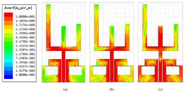
IV. CURRENTDISTRIBUTIONSANDRADIATIONPATTERNS
In order to better understand the antenna behavior, the current distributions of the three-band
antenna at frequencies of 2.47 GHz, 3.20 GHz and 4.92 GHz are simulated and shown respectively in
figures 10 (a), (b) and (c).
L1= 3.8 mm
L1= 4.3 mm
L1= 4.8 mm
Re (Z), g= 0.1 mm
Re (Z), g= 0.2 mm
Re (Z), g= 0.3 mm Re (Z), g= 0.35 mm
Im (Z), g= 0.1 mm
Im (Z), g= 0.2 mmIm (Z), g= 0.3 mm
(a) (b) (c)
Fig. 10. Simulated surface current distributions of the proposed antenna at frequencies (a) 2.47 GHz, (b) 3.20 GHz and
(c) 4.92 GHz.
It can be evidently seen from Fig. 10 that the current distribution at the three resonant frequencies
is different. Concerning the first resonant mode (2.47 GHz), a large surface of the current density is
observed along the inverted L-shaped Stub1. Whereas for the second frequency band (3.20 GHz),
the current distribution is mainly distributed along the inverted L-shaped Stub2, on the other hand
for the third resonant mode (4.92 GHz), the current distribution becomes more concentrated along
the Stub3. Nevertheless, they also have a common characteristic that is a large current is
concentrated along the feed line.
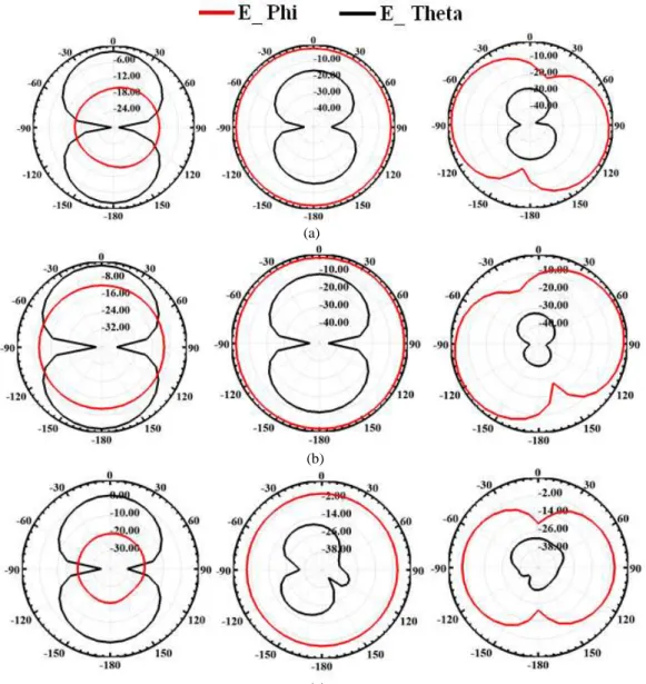
The simulated radiation patterns of the proposed antenna are shown in figures 11(a), (b) and (c) at
2.47, 3.20, and 4.92 GHz, respectively. It can be obviously noticed that the nearly omni-directional
radiation in the H-plane (yz-plane) and like a dipole radiation patterns (bi-directional) in the E-plane
(xz-plane) are obtained at these frequencies.
The simulated antenna gain against frequency for the proposed antenna across the three bands is
shown in Fig. 12. First over the 2.4 GHz operation band (2.085 - 2.72 GHz); the simulated gain is
varied from -2.4 dBi to -0.08 dBi. Then for the medium band (2.89 - 4.35 GHz), the simulated
antenna gain is about -1.27 dBi to 2.62 dBi. Finally at the higher band (4.59 - 7.055 GHz), the
(a)
(b)
(c)
Fig. 11. Simulated radiation pattern of the proposed antenna at different frequencies (a) 2.47 GHz, (b) 3.20 GHz, and (c)
4.92 GHz.
1 2 3 4 5 6 7 8
-5 -4 -3 -2 -1 0 1 2 3 4 5
Frequency (GHz)
A
n
te
n
n
a
G
a
in
(
d
B
i)
V. CONCLUSION
A simple miniaturized triple wideband CPW-fed patch antenna with a defected ground structure
was proposed with its parametric study. The substrate size of the proposed antenna is 20×37mm2 with
a thickness of 0.508 mm. The simulated result shows that the impedance bandwidths are from 2.085
to 2.72 GHz, 2.89 to 4.35 GHz and 4.59 to 7.055 GHz, covering all the 2.4/5.2/5.8 GHz WLAN bands
and 2.5/3.5/5.5 GHz WiMAX bands by using two separate resonant inverted L-shaped Stubs (Stub1
and Stub2) and a rectangle Stub3. The three resonant frequencies of the proposed antenna can be
tuned individually by adjusting the length of the three Stubs. Accordingly, the proposed antenna is
expected to be a good candidate for WLAN/WiMAX wireless communication systems.
ACKNOWLEDGMENT
This work is supported by the National Center for Scientific and Technical Research.
REFERENCES
[1] J. Anguera, A. Andújar, M.C. Huynh, C. Orlenius, C. Picher, and C. Puente, “Advances in Antenna Technology for
Wireless Handheld Devices,” International Journal on Antennas and Propagation, Volume 2013. Article ID 838364.
[2] K.L. Wong, “Planar Antennas for Wireless Communications,” Wiley Inter-Science 2003.
[3] S. S. Huang, J. Li, and J. Z. Zhao, “A Novel Compact Planar Triple-Band Monopole Antenna for WLAN/WiMAX
Applications,” Progress in Electromagnetics Research Letters, Vol. 50, pp. 117–123, 2014.
[4] A. Mehdipour, A.-R. Sebak, C. W. Trueman, and T. A. Denidni, “Compact Multiband Planar Antenna for
2.4/3.5/5.2/5.8-GHz Wireless Applications,” IEEE Antennas Wireless Propag Lett, Vol. 11, pp.144-147, 2012.
[5] L. Xu, Z. Y. Xin, and J. He,“A Compact Triple-Band Fork-Shaped Antenna for WLAN/WiMAX Applications,” Progress in Electromagnetics Research Letters, Vol. 40, pp. 61-69, 2013.
[6] W.-C. Liua, C.-M.Wua, and N.-C.Chub, “A compact low-profile dual-band antenna for WLAN and WAVE
applications,” Int. J. Electron. Commun. (AEÜ), Vol. 66, Issue. 6, pp. 467– 471, 2012.
[7] C. -M. Wu, “Wideband dual-frequency CPW-fed triangular monopole antenna for DCS/WLAN application,”Int. J.
Electron. Commun. (AEÜ), Vol. 61, pp. 563-567, 2007.
[8] M. Naser-Moghadasi, A. Danideh, A. Bakhtiari, and R. Sadeghifakhr, “Compact Slot Antenna for MIMO Applications
in the WLAN Bands,” Microwave and Optical Technology Letters, Vol. 55, pp. 2490-2493, 2013.
[9] W.-C. Liu, C.-M. Wu and N.-C. Chu, “A Compact CPW-Fed Slotted Patch Antenna for Dual-Band Operation,” IEEE
Antennas Wireless Propag Lett, Vol. 9, pp. 110-113, 2010.
[10]T. -L. Zhang, Z. -H. Yan, L. Chen, and Y. Song, “A Compact Dual-Band CPW-fed Planar Monopole Antenna for
WLAN Applications,” J. of Electromagn.Waves and Appl, vol. 22, pp. 2097–2104, 2008.
[11]J. Kaur, R. Khanna, and M.A. Kartikeyan, “Novel Dual-Band Multistrip Monopole Antenna with Defected Ground
Structure for WLAN/IMT/BLUETOOTH/WiMAX Applications,”International Journal of Microwave and Wireless
Technologies, Vol. 6, Special Issue 01, pp. 93-100, Feb. 2014.
[12]Y. Zhuo, L. Yan, X. Zhao, and K. Huang, “A Compact Dual-Band Patch Antenna for WLAN applications,” Progress in
Electromagnetics Research Letters, Vol. 26, pp. 153-160, 2011.
[13] J. H. Yoon, “Fabrication and Measurement of Rectangular Ring with Open-ended CPW-Fed Monopole Antenna for 2.4/5.2-GHz
WLAN Operation,” Microwave and Optical Technology Letters, Vol. 48, no. 8, pp. 1480-1483, Aug. 2006.
[14]S. Gai, Y.-C. Jiao, Y.-B. Yang, C.-Y. Li and J.-G. Gong, “Design of a Novel Microstrip-Fed Dual-Band Slot Antenna
for WLAN Applications,” Progress in Electromagnetics Research Letters, Vol. 13, pp. 75-81, 2010.
[15]L. Peng and C.-L. Ruan, “A Microstrip Fed Monopole Patch Antenna with three Stubs for Dual-band WLAN
Applications,” J. of Electromagn.Waves and Appl, Vol. 21, no. 15, pp. 2359–2369, 2007.
[16]D.Parkash, R. Khanna, “Design of a Dual Band Monopole Antenna for WLAN/WiMAX Applications,” in Proc. 7th
WOCN, Sep. 6–8, 2010.
[17] L. Zhang, Y. -C. Jiao, G. Zhao, Y. Song, and F. -S. Zhang, “Broadband Dual-Band CPW-Fed Closed Rectangular Ring
Monopole Antenna with A Vertical Strip for WLAN Operation,” Microwave and Optical Technology Letters, Vol. 50,
[18]R. Dakir, J. Zbitou, A. Mouhsen, A. Tribak, A. Sanchez and M. Latrach,“New Low-Cost Broadband CPW-Fed Planar
Antenna,” International Journal of Microwave and Wireless Technologies, Research Paper, 6 pages, 11 Dec. 2014.
[19]J. Pei, A. –G. Wang, S. Gao, and W. Leng, “Miniaturized Triple-Band Antenna with a Defected Ground Plane for
WLAN/WiMAX Applications,”IEEE Antennas Wireless Propag Lett, Vol. 10, pp. 298-301, 2011.
[20]R. Jothi Chitra, V. Nagarajan, “Double L-slot Microstrip Patch Antenna Array for WiMAX and WLAN Applications,”
Computers and Electrical Engineering, Vol. 39, pp. 1026–1041, 2013.
[21]W.-C. Liu and C.-F. Hsu, “Dual-Band CPW-Fed Y-Shaped Monopole Antenna for PCS/WLAN Application,”
Electronics Letters, Vol. 41, no. 7, pp. 390-391, Mar. 2005.
[22]G. Augustin, P. C. Bybi, V. P. Sarin, P. Mohanan, C. K. Aanandan, and K. Vasudevan, “A Compact Dual-Band Planar
Antenna for DCS-1900/PCS/PHS, WCDMA/IMT-2000, and WLAN Applications,” IEEE Antennas Wireless Propag
Lett, Vol. 7, pp. 108-111, 2008.
[23]Q. Zhao, S. X. Gong, W. Jiang, B. Yang, and J. Xie, “Compact Wide-Slot Tri-Band Antenna for WLAN/WIMAX
Applications,” Progress In Electromagnetics Research Letters, Vol. 18, pp. 9-18, 2010.
[24] X.L. Sun, J. Zhang, S.W. Cheung, and T.I. Yuk, “A Triple-band Monopole Antenna for WLAN and WiMAX
Applications,” in Proc. IEEE International Symposium (APSURSI), 8-14 Jul. 2012, pp.1-2.
[25]L. Kang, Y.-Z. Yin, H. Li, W.-J. Huang and S.-F. Zheng, “Dual-Wideband Symmetrical G-Shaped Slotted Monopole
Antenna for WLAN/WIMAX Applications,” Progress In Electromagnetics Research Letters, Vol. 17, pp. 55-65, 2010.
[26]W.C. Liu, “Dual Wideband Coplanar Waveguide-Fed Notched Antennas with Asymmetrical Grounds for Multi-Band
Wireless Application,” IET Microw. Antennas Propag, Vol. 1, no. 5, pp. 980-985, Oct. 2007.
[27]C.-Y. Pan, T.-S. Horng, W.-S. Chenand C.-H. Huang, “Dual Wideband Printed Monopole Antenna for
WLAN/WiMAX Applications,”IEEE Antennas Wireless Propag Lett, vol. 6, pp.149-151, 2007.
[28]H. M. El Misilmani, M. Al-Husseini, K. Y. Kabalan, and A. El-Hajj, “A Simple Miniaturized Triple-band Antenna for
WLAN/WiMAX Applications,” in PIERS Proceedings, Moscow, Russia, Aug. 19-23, 2012, pp. 608-612.
[29]Y. Song, Y.-C. Jiao, G. Zhao, and F.-S. Zhang, “Multiband CPW-Fed Triangle-Shaped Monopole Antenna for Wireless
Applications,”Progress in Electromagnetics Research, PIER, Vol. 70, pp. 329-336, 2007.
[30]P. Liu, Y. Zou, B. Xie, X. Liu, and B. Sun, “Compact CPW-Fed Tri-Band Printed Antenna With Meandering
Split-Ring Slot for WLAN/WiMAX Applications,” IEEE Antennas Wireless Propag Lett, Vol. 11, pp.1242-1244, 2012.
[31]W. Hu, Y. -Z. Yin, P. Fei, and X. Yang, “Compact Tri band Square-Slot Antenna with Symmetrical L-Strips for
WLAN/WiMAX Applications,” IEEE Antennas Wireless Propag Lett, vol. 10, pp.462-465, 2011.
[32]Q.-X. Chu and L.-H. Ye, “Design of Compact Dual-Wideband Antenna with Assembled Monopoles,” IEEE
Transactions on Antennas and Propagation, vol. 58, no. 12, pp.4063-4066, Dec. 2010.
[33]Yi Huang; Kevin Boyle.: Antennas from Theory to Practice, 2008 John Wiley & Sons Ltd.
[34]A. Cabedo, J. Anguera, C. Picher, M. Ribó, and C. Puente, “Multi-Band Handset Antenna Combining a PIFA, Slots,
and Ground Plane Modes”, IEEE Transactions on Antennas and Propagation, vol.57, no. 9, pp. 2526-2533, Sep. 2003. [35]M.F. Abedin, and M. Ali, “Modifying the Ground Plane and Its Effects on Planar Inverted-F Antennas (PIFAs) for
Mobile Phone Handsets”, IEEE Antennas and Wireless Propagation Letters, vol.2, pp.226-229, 2003 .
[36]J. Anguera, I. Sanz, J. Mumbrú, and C. Puente, “Multi-Band Handset Antenna with a Parallel Excitation of PIFA and