Abstract
This paper investigates the behaviour of axially loaded stiffened concrete-filled steel composite (CFSC) stub columns using the finite element software LUSAS. Modelling accuracy is established by com-paring results of the nonlinear analysis and the experimental test. The CFSC stub columns are extensively developed using different special arrangements, number, spacing, and diameters of bar stiffen-ers with various steel wall thicknesses, concrete compressive strengths, and steel yield stresses. Their effects on the columns be-haviour are examined. Failure modes of the columns are also illus-trated. It is concluded that the parameters have considerable effects on the behaviour of the columns. An equation is proposed based on the obtained results to predict the ultimate load capacity of the col-umns. Results are compared with predicted values by the design code EC4, suggested equation of other researchers, and proposed equation of this study which is concluded that the proposed equation can give closer predictions than the others.
Keywords
Stub column, concrete, nonlinear analysis, bar stiffener, ultimate load capacity, ductility.
Behaviour of stiffened concrete-filled steel composite (CFSC)
stub columns
1 INTRODUCTION
The strength and stiffness of concrete-filled steel composite (CFSC) columns are optimised by the loca-tion of steel and concrete in their cross-secloca-tions. Steel is situated at the outer perimeter where it acts most efficiently in tension and in withstanding bending moments. Also, the stiffness of CFSC columns is considerably increased since the steel lies farthest from the centroid, where it contributes the greatest to the moment of inertia. Concrete makes an ideal core to resist compressive loads [4]. Inward buckling of the steel wall is prevented by the concrete core which leads to the delay of the local buckling of the steel wall. Whilst spalling of the concrete core is prevented by the steel wall. Also, the steel wall elimi-nates the need for the longitudinal and transverse reinforcements and it behaves as permanent form-work to the concrete core which results in reducing materials and labours costs [10]. The steel con-sumption in CFSC columns is less than the steel columns leading to cost saving. On the other hand, CFSC columns have structural benefits such as high strength, large stiffness, and high ductility. Also, the sur-face of concrete is protected from damage by the steel wall in CFSC columns. Simple connections can be utilised between steel floor beams and CFSC columns and extra work is not required to make the col-umns stiffer in the area of the connection. In CFSC colcol-umns, deformations due to shrinkage are negligi-ble and deformations owing to creep are about one third of their reinforced concrete counterparts. By
Alireza Bahrami*
Wan Hamidon Wan Badaruzzaman Siti Aminah Osman
Department of Civil and Structural Engineer-ing, Universiti Kebangsaan Malaysia, Bangi, Selangor, Malaysia
Received 29 Jun 2012 In revised form 8 Oct 2012
the use of CFSC columns, several floors can be constructed and construction loadings can be supported before the concrete filling during the construction stage which highlights using CFSC columns as a cost effective structural element in multi-storey buildings. The cross-sectional area of CFSC columns can be reduced owing to higher strength of the columns. Steel plate thickness can be decreased which leads to more savings in weight and material. The use of CFSC columns increases the speed of the construction process of a building in the upper stories which is because of the point that steel elements of higher levels can be fabricated even if concrete has not been filled in the lower column [34]. Moreover, CFSC columns have ecological benefits over reinforced concrete columns: reinforcement and formwork are not used in CFSC columns which brings about a clean construction site; high strength concrete in CFSC columns which does not possess reinforcement can be crushed easily and reutilised as aggregates when the building is demolished; and the steel wall that peels from the concrete core can be reused [32]. The aforementioned advantages of CFSC columns have shown their priority over steel and rein-forced concrete columns and have also resulted in their expanding usage in modern construction pro-jects throughout the world.
A high fire resistance can be achieved for CFSC columns compared to hollow steel tubular columns [18]. Although, steel is a highly thermal conductive material, it quickly loses its strength and stiffness under fire exposure [6]. Bailey [3] noted that for steel tubular columns, different fire protection meth-ods may be used to improve the fire resistance which are mostly expensive and do not strengthen the columns. Concrete-infill has been considered as an effective temperature sink which decreases the temperature in the steel wall during fire. Moreover, since the temperature of the concrete core is in-creased much slower than that of the steel wall, the concrete core can afford proper load capacity even when the steel wall has a high temperature. When a CFSC column is subjected to fire, the different thermal properties of steel and concrete, and the steel wall trapping the concrete core can lead to hav-ing higher temperature for the steel wall than the concrete core. The different thermal expansions in the steel wall and the concrete core decrease their interaction. In the initial stage of exposure to fire, the steel wall carries the load [40]. Then, since the steel wall attains critical temperature it yields which is led to the significant decrease of its strength. Therefore, the load is transferred from the steel wall to the concrete core. The concrete core prevents the steel wall from inward buckling. But, after fire expo-sure, outward buckling can be occurred meaning the local separation of the steel wall and the concrete core, and finally the column fails [22]. Since the fire resistance of CFSC columns is higher than that of hollow steel tubular columns, it is not needed to provide external protection in most cases [38]. How-ever, according to Lua et al. [29], there are several methods for further improvement of the fire re-sistance of CFSC columns such as using external fire insulation coating, utilising steel reinforcements in the concrete core and using high performance concrete ([16], [22], [25]). Also, adding fibres to concrete is an effective method in order to obtain high performance concrete to attain higher fire resistance ([23], [31]).
preload on the axial capacity of the columns. Tao et al. [43] conducted experiments on concrete-filled stiffened thin-walled steel tubular columns under axial loading. Tests on concrete-filled double skin columns were carried out under compression by Uenaka et al. [45]. Oliveira et al. [36] experimentally evaluated passive confinement effect of the steel tube in concrete-filled steel tubular columns. An ex-perimental and analytical investigation on concrete-filled tubes with critical lengths ranging from 131 cm to 467 cm was performed by Muciaccia et al. [33]. Uy et al. [47] tested short and slender concrete-filled stainless steel tubular columns to investigate their performance under axial compression and combined action of axial force and bending moment. Nonlinear behaviour of concrete-filled steel com-posite slender columns was studied by Bahrami et al. [1] to evaluate and develop different shapes (V, T, L, Line, & Triangular) and number (1 on side & 2 on side) of longitudinal cold-formed steel sheeting stiffeners and also to assess their effects on the structural behaviour of the columns. However, research works on the behaviour of stiffened CFSC stub columns are limited.
This paper deals with the behaviour of the stiffened concrete-filled steel composite (CFSC) stub col-umns subjected to axial loading. Verification of the proposed three-dimensional (3D) finite element modelling is performed by comparison of the finite element result with the existing experimental result presented by Tao et al. [42]. The verification demonstrates that the proposed finite element modelling of this study can accurately predict the behaviour of the columns. The CFSC stub columns are widely developed using different special arrangements, number, spacing, and diameters of bar stiffeners with various steel wall thicknesses, concrete compressive strengths, and steel yield stresses. Extensive pa-rameters are considered in the nonlinear finite element analyses to investigate the behaviour of the columns. The main parameters are: (1) arrangements of bar stiffeners (C1 and C2); (2) number of bar stiffeners (2, 3, and 4); (3) spacing of bar stiffeners (from 50 mm to 150 mm); (4) diameters of bar stiffeners (from 8 mm to 12 mm); (5) steel wall thicknesses (from 2 mm to 3 mm); (6) concrete com-pressive strengths (from 30 MPa to 50.1 MPa), and (7) steel yield stresses (from 234.3 MPa to 450 MPa). Effects of different number and spacing of the bar stiffeners and also steel wall thicknesses on the ultimate load capacity and ductility of the columns are examined. In addition, effects of various ar-rangements and diameters of the bar stiffeners, concrete compressive strengths, and steel yield stress-es on the ultimate load capacity of the columns are evaluated. Failure modstress-es of the columns are as-sessed. An equation is also proposed based on the obtained results to predict the ultimate load capacity of the columns. The ultimate load capacities achieved from the nonlinear finite element analyses are compared with predicted values by the design code EC4 [11], equation of other researchers, and pro-posed equation of this study.
2 FINITE ELEMENT MODELLING
The nonlinear 3D finite element modelling was conducted by the use of the finite element software LUSAS to simulate the CFSC stub columns. The stub column experiment carried out by Tao et al. [42] has been chosen for the nonlinear finite element modelling in this paper. The steel wall thickness (t) and cross-section of the column were 2.5 mm and 249 mm × 250.4 mm, respectively, as shown in Fig-ure 1. The length of the column was 750 mm.
Steel wall Concrete core
B = 249
H =
250.
4
Figure 1 Cross-section of unstiffened CFSC stub column, (unit: mm)
In order to accurately simulate the actual behaviour of the columns, crucial parameters such as fi-nite element type, mesh, concrete-steel interface, boundary conditions, and load application are needed to be taken into account in the simulation of the columns. Meanwhile, constitutive models of the steel wall, steel bar stiffeners, and concrete are important which should be suitably considered in the model-ling.
2.1 Finite Element Type, Mesh, Concrete-Steel Interface, Boundary Conditions, and Load Application
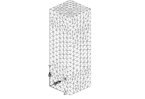
The element library of the finite element software LUSAS (Finite Element Analysis Ltd. [12]) was used to select the type of elements for the steel wall and concrete core of the columns in this study. The 6-noded triangular shell element, TSL6, was used for modelling of the steel wall. This is a thin, doubly curved, isoparametric element which can be utilised to model 3D structures. This element can accom-modate generally curved geometry with varying thickness and anisotropic and composite material properties. The element formulation takes account of both membrane and flexural deformations. The steel bar stiffeners were modelled by the 3-noded bar element type BRS3. This is an isoparametric bar element in 3D which can accommodate varying cross-sectional area. This element is suitable for model-ling stiffening reinforcement with continuum elements. The 10-noded tetrahedral element, TH10, was utilised to model the concrete core. This is a 3D isoparametric solid continuum element capable of modelling curved boundaries. This type of element is a standard volume element of the LUSAS soft-ware.
Figure 2 A typical finite element mesh
Slidelines were employed to represent the contact between the concrete core and steel (comprising steel wall and steel bar stiffeners). The slidelines are attributes which can be utilised to model contact surfaces in the finite element software LUSAS. The slideline contact facility is nonlinear and was used in the nonlinear analyses. Slave and master surfaces needed to be correctly selected to provide the contact between surfaces of steel and concrete. If a smaller surface is in contact with a larger surface, the small-er surface can be best selected as the slave surface. If it is not possible to distinguish this point, the body which possesses higher stiffness should be selected as the master surface. It needs to be highlighted that the stiffness of the structure should be considered not just the material. Although, the steel materi-al is stiffer than the concrete materimateri-al, steel may have less stiffness than the volume of the concrete core herein. As a result, the concrete core and steel surfaces were respectively selected as the master and slave surfaces. This process of choosing master and slave surfaces has been also stated by Dabaon et al.
[5]. The definition of properties such as friction coefficient is allowed in the slidelines. The friction be-tween two surfaces, the concrete core and steel, is considered so that they can be in contact. The Cou-lomb friction coefficient in the slidelines was chosen as 0.25. The slidelines allow the concrete core and steel to separate or slide but not to penetrate each other.
Pin-ended supports of the corresponding experiment have been accurately simulated in the finite element modelling in this study. Accordingly, the rotations of the top and bottom surfaces of the col-umns in the X, Y, and Z directions were considered to be free. Also, the displacements of the top and bottom surfaces in the X and Z directions were restrained. On the other hand, the displacement of the bottom surface in the Y direction was restrained while that of the top surface, in the direction of the applied load and where the load was applied, was set to be free. The axial loading of the experiment has been appropriately simulated using incremental displacement load with an initial increment of 1 mm applied axially to the top surface of the columns in the negative Y direction.
2.2 Constitutive Models
Materials used in the numerical analysis consist of steel wall, steel bar stiffener, and concrete. Constitu-tive models of the materials play a vital role in the behaviour of the columns and are presented in the following:
2.2.1 Steel Wall
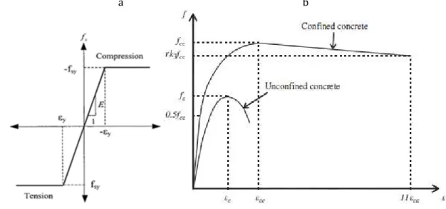
Modelling of the steel wall has been carried out as an elastic-perfectly plastic material in both tension and compression. The stress-strain curve used for the steel wall is shown in Figure 3(a). The yield stress, modulus of elasticity, and Poisson’s ratio of the steel wall have been respectively taken as 234.3 MPa, 208,000 MPa, and 0.247 that are identical to those in the corresponding experiment. Von Mises yield criterion, an associated flow rule, and isotropic hardening have been also utilised in the nonlinear material model.
2.2.2 Steel Bar Stiffener
The uniaxial behaviour of the steel bar stiffener is similar to that of the steel wall. Therefore, it can be simulated by the elastic-perfectly plastic material model (Figure 3(a)). The yield stress and modulus of elasticity of the steel bar stiffener have been considered as 400 MPa and 200,000 MPa, respectively.
The compressive strength and modulus of elasticity of concrete have been respectively adopted as 50.1 MPa and 35,100 MPa which are the same as those in the corresponding experiment. Figure 3(b) shows the equivalent uniaxial stress-strain curves for concrete (Ellobody and Young [7, 8]) which have been used in this study to model concrete. The unconfined concrete cylinder compressive strength fc = 0.8fcu in which fcu is the unconfined concrete cube compressive strength. In accordance with Hu et al. [19], the corresponding unconfined strain εc is usually around the range of 0.002-0.003. They considered εc as 0.002. The same value for εc has been also taken in the analysis herein. When concrete is under laterally confining pressure, the confined compressive strength fcc and the corresponding confined strain εcc are much greater than those of unconfined concrete.
a b
Figure 3 Stress-strain curves: (a) steel, (b) concrete
Equations (1) and (2) have been used to respectively obtain the confined concrete compressive strength fcc and the corresponding confined stain εcc, as presented by Mander et al. [30]:
(1)
(2)
where f1 is the lateral confining pressure of the steel wall on the concrete core. The approximate value of f1 can be interpolated from the values reported by Hu et al. [20]. According to Richart et al. [37], the factors of k1 and k2 have been taken as 4.1 and 20.5, respectively. Since f1, k1 and k2are known fcc and εcc can be calculated by the use of Equations (1) and (2). The equivalent uniaxial stress-strain curve for confined concrete (Figure 3(b)) comprises three parts which are needed to be defined. The first part consists of the initially assumed elastic range to the proportional limit stress. The value of the propor-tional limit stress has been adopted as 0.5fcc, as recommended by Hu et al. [20]. The empirical Equation (3) has been used to determine the initial Young’s modulus of confined concrete Ecc. The Poisson’s ratio υcc of confined concrete has been considered as 0.2.
The second part includes the nonlinear portion which starts from the proportional limit stress 0.5fcc to the confined concrete strength fcc. The common Equation (4) presented by Saenz [39] can be used to determine this part. The values of uniaxial stress f and strain ε are the unknowns of the equation which define this part of the curve. The strain values ε have been considered between the proportional strain (0.5fcc/Ecc), and the confined strain εcc which corresponds to the confined concrete strength. Equation (4) can be used to determine the stress values f by assuming the strain values ε.
(4)
in which RE and R are:
The constants Rε and Rσ have been adopted as 4 in this study, as reported by Hu and Schnobrich [21]. The third part of the curve is the descending part which is between fcc and rk3fcc with the corre-sponding strain of 11εcc. k3 is the reduction factor dependent on the H/t ratio. Empirical equations proposed by Hu et al. [20] can be utilised to determine the approximate value of k3. To consider the effect of different concrete strengths, the reduction factor r was introduced by Ellobody et al. [9] on the basis of the experimental study carried out by Giakoumelis and Lam [13]. According to Tomii [44] and also Mursi and Uy [35], the value of r has been adopted as 1.0 for concrete with cube strength fcu equal to 30 MPa and as 0.5 for concrete with fcu greater than or equal to 100 MPa. The value of r for concrete cube strength between 30 MPa and 100 MPa has been calculated by the use of linear interpolation.
2.3 Modelling Verification
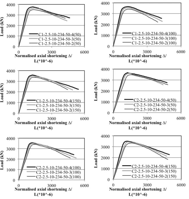
Figure 4 Load versus normalised axial shortening curves for the CFSC stub columns
3 NUMERICAL ANALYSIS
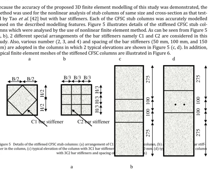
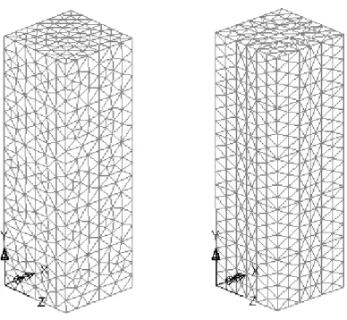
Because the accuracy of the proposed 3D finite element modelling of this study was demonstrated, the method was used for the nonlinear analysis of stub columns of same size and cross-section as that test-ed by Tao et al. [42] but with bar stiffeners. Each of the CFSC stub columns was accurately modelled based on the described modelling features. Figure 5 illustrates details of the stiffened CFSC stub col-umns which were analysed by the use of nonlinear finite element method. As can be seen from Figure 5 (a, b), 2 different special arrangements of the bar stiffeners namely C1 and C2 are considered in this study. Also, various number (2, 3, and 4) and spacing of the bar stiffeners (50 mm, 100 mm, and 150 mm) are adopted in the columns in which 2 typical elevations are shown in Figure 5 (c, d). In addition, typical finite element meshes of the stiffened CFSC columns are illustrated in Figure 6.
a b c d
Figure 5 Details of the stiffened CFSC stub columns: (a) arrangement of C1 bar stiffener in the column, (b) arrangement of C2 bar stiff-ener in the column, (c) typical elevation of the column with 3C1 bar stiffstiff-eners and spacing of 100 mm, (d) typical elevation of the column
with 3C2 bar stiffeners and spacing of 100 mm; (unit: mm)
a b
Experiment
H/ 3 H/ 3 H/ 3B/2 B/2
H/ 2 H/ 2
C1 bar stiffener C2 bar stiffener
2 75 100 1 00 27 5
• •
2 75 100 1 00 27 5
Figure 6 Typical finite element meshes of the stiffened CFSC stub columns: (a) column with 4C1 bar stiffeners and spacing of 150 mm, (c) column with 4C2 bar stiffeners and spacing of 150 mm
4 RESULTS AND DISCUSSION
Table 1 summarises specifications and obtained ultimate load capacities of the analysed CFSC stub col-umns. C1 and C2 in the column labels represent the columns with different special arrangements of the bar stiffeners as illustrated in Figure 5 (a, b). The first four numbers following C1 and C2 respectively denote the steel wall thickness t (mm), diameter of bar stiffener D (mm), steel wall yield stress fy (MPa), and concrete compressive strength fc (MPa). Also, the number before the parentheses is the number of the bar stiffeners and the number in the parentheses represents the centre-to-centre spac-ing (mm) between the bar stiffeners. Moreover, the load eccentricity (e) for those eccentrically loaded columns is added to the columns labels as the last number after the parentheses, i.e. 30 and 60 respec-tively stand for the load eccentricities of 30 mm and 60 mm. Effects of various parameters on the be-haviour of the columns are presented in the following sections.
Table 1 Specifications and ultimate load capacities (Nu) of the columns
No. Column label Steel wall
t (mm)
Bar stiffener D (mm)
Steel wall fy (MPa)
Concrete fc (MPa)
Nu (kN)
1 C1-2.5-10-234-50-4(50) 2.5 10 234.3 50.1 3760
3 C1-2.5-10-234-50-2(50) 2.5 10 234.3 50.1 3517
4 C1-2.5-10-234-50-4(100) 2.5 10 234.3 50.1 3656
5 C1-2.5-10-234-50-3(100) 2.5 10 234.3 50.1 3557
6 C1-2.5-10-234-50-2(100) 2.5 10 234.3 50.1 3424
7 C1-2.5-10-234-50-4(150) 2.5 10 234.3 50.1 3579
8 C1-2.5-10-234-50-3(150) 2.5 10 234.3 50.1 3486
9 C1-2.5-10-234-50-2(150) 2.5 10 234.3 50.1 3359
10 C2-2.5-10-234-50-4(50) 2.5 10 234.3 50.1 3668
11 C2-2.5-10-234-50-3(50) 2.5 10 234.3 50.1 3583
12 C2-2.5-10-234-50-2(50) 2.5 10 234.3 50.1 3473
13 C2-2.5-10-234-50-4(100) 2.5 10 234.3 50.1 3575
14 C2-2.5-10-234-50-3(100) 2.5 10 234.3 50.1 3499
15 C2-2.5-10-234-50-2(100) 2.5 10 234.3 50.1 3398
16 C2-2.5-10-234-50-4(150) 2.5 10 234.3 50.1 3510
17 C2-2.5-10-234-50-3(150) 2.5 10 234.3 50.1 3445
18 C2-2.5-10-234-50-2(150) 2.5 10 234.3 50.1 3348
19 C1-3-10-234-50-4(50) 3 10 234.3 50.1 3905
20 C1-2-10-234-50-4(50) 2 10 234.3 50.1 3596
21 C1-3-10-234-50-3(50) 3 10 234.3 50.1 3793
22 C1-2-10-234-50-3(50) 2 10 234.3 50.1 3525
23 C1-3-10-234-50-2(50) 3 10 234.3 50.1 3665
24 C1-2-10-234-50-2(50) 2 10 234.3 50.1 3368
25 C2-3-10-234-50-4(50) 3 10 234.3 50.1 3825
26 C2-2-10-234-50-4(50) 2 10 234.3 50.1 3516
27 C2-3-10-234-50-3(50) 3 10 234.3 50.1 3732
28 C2-2-10-234-50-3(50) 2 10 234.3 50.1 3437
29 C2-3-10-234-50-2(50) 3 10 234.3 50.1 3622
30 C2-2-10-234-50-2(50) 2 10 234.3 50.1 3320
31 C1-2.5-12-234-50-4(50) 2.5 12 234.3 50.1 3804
32 C1-2.5-8-234-50-4(50) 2.5 8 234.3 50.1 3695
33 C1-2.5-12-234-50-3(50) 2.5 12 234.3 50.1 3721
34 C1-2.5-8-234-50-3(50) 2.5 8 234.3 50.1 3597
Table 1 continued
No. Column label Steel wall
t (mm)
Bar stiffener D (mm)
Steel wall fy (MPa)
Concrete fc (MPa)
Nu (kN)
35 C1-2.5-12-234-50-2(50) 2.5 12 234.3 50.1 3544
37 C2-2.5-12-234-50-4(50) 2.5 12 234.3 50.1 3719
38 C2-2.5-8-234-50-4(50) 2.5 8 234.3 50.1 3622
39 C2-2.5-12-234-50-3(50) 2.5 12 234.3 50.1 3661
40 C2-2.5-8-234-50-3(50) 2.5 8 234.3 50.1 3505
41 C2-2.5-12-234-50-2(50) 2.5 12 234.3 50.1 3506
42 C2-2.5-8-234-50-2(50) 2.5 8 234.3 50.1 3438
43 C1-2.5-10-234-50-4(50)-30 2.5 10 234.3 50.1 3086
44 C1-2.5-10-234-50-4(50)-60 2.5 10 234.3 50.1 2425
45 C1-2.5-10-234-50-4(100)-30 2.5 10 234.3 50.1 2926
46 C1-2.5-10-234-50-4(100)-60 2.5 10 234.3 50.1 2225
47 C1-2.5-10-234-40-4(50) 2.5 10 234.3 40 3138
48 C1-2.5-10-234-30-4(50) 2.5 10 234.3 30 2520
49 C1-2.5-10-234-40-3(50) 2.5 10 234.3 40 3063
50 C1-2.5-10-234-30-3(50) 2.5 10 234.3 30 2449
51 C1-2.5-10-234-40-2(50) 2.5 10 234.3 40 2942
52 C1-2.5-10-234-30-2(50) 2.5 10 234.3 30 2347
53 C2-2.5-10-234-40-4(50) 2.5 10 234.3 40 3077
54 C2-2.5-10-234-30-4(50) 2.5 10 234.3 30 2468
55 C2-2.5-10-234-40-3(50) 2.5 10 234.3 40 3021
56 C2-2.5-10-234-30-3(50) 2.5 10 234.3 30 2446
57 C2-2.5-10-234-40-2(50) 2.5 10 234.3 40 2909
58 C2-2.5-10-234-30-2(50) 2.5 10 234.3 30 2329
59 C1-2.5-10-450-50-4(50) 2.5 10 450 50.1 4375
60 C1-2.5-10-350-50-4(50) 2.5 10 350 50.1 4102
61 C1-2.5-10-450-50-3(50) 2.5 10 450 50.1 4219
62 C1-2.5-10-350-50-3(50) 2.5 10 350 50.1 3976
63 C1-2.5-10-450-50-2(50) 2.5 10 450 50.1 4067
64 C1-2.5-10-350-50-2(50) 2.5 10 350 50.1 3853
65 C2-2.5-10-450-50-4(50) 2.5 10 450 50.1 4257
66 C2-2.5-10-350-50-4(50) 2.5 10 350 50.1 4011
67 C2-2.5-10-450-50-3(50) 2.5 10 450 50.1 4104
68 C2-2.5-10-350-50-3(50) 2.5 10 350 50.1 3906
Table 1 continued
No. Column label Steel wall
t (mm)
Bar stiffener D (mm)
Steel wall fy (MPa)
Concrete fc (MPa)
Nu (kN)
70 C2-2.5-10-350-50-2(50) 2.5 10 350 50.1 3807
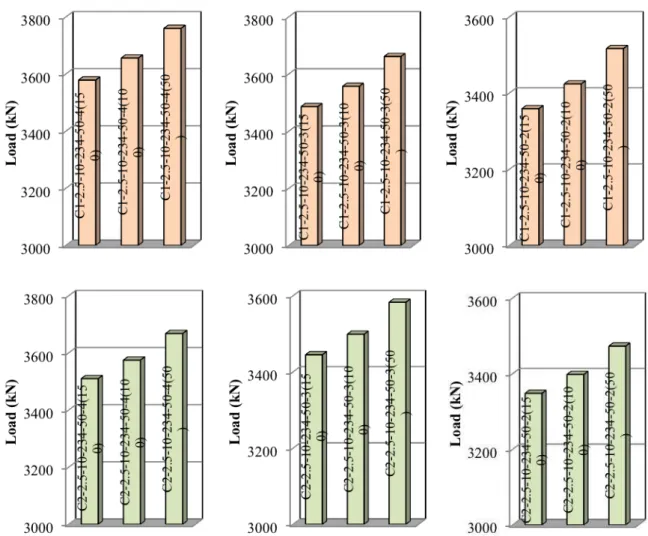
4.1 Effects of Arrangement and Number of Bar Stiffeners on Ultimate Load Capacity
The CFSC stub columns with two different special arrangements of bar stiffeners, C1 and C2, (Figure 5(a, b)) and various number of the bar stiffeners (2, 3, and 4) were analysed to investigate their effects on the behaviour of the columns. These effects on the ultimate load capacity are illustrated in Figure 7. Table 1 also summarises the corresponding ultimate load capacity values of the curves.
As can be seen from the figure and table, the use of the bar stiffeners increases the ultimate load ca-pacity of the unsiffened CFSC stub column. As an example, the ultimate load caca-pacity of the unstiffened column is 3325 kN which increases to 3760 kN by the use of 4C1 bar stiffeners (C1-2.5-10-234-50-4(50)), an improvement of 13.1%. Also, using 4C2 bar stiffeners (C2-2.5-10-234-50-4(50)) leads to the ultimate load capacity of 3668 kN which is 10.3% higher than that of the unstiffened column. Therefore, the use of C1 bar stiffeners uncovered to be more effective on the increase of the ultimate load capacity of the unstiffened CFSC columns than C2 bar stiffeners. Moreover, as the number of the bar stiffeners is enhanced the ultimate load capacity is improved. For instance, the ultimate load capacity of the column with 2C1 bar stiffeners and spacing of 100 mm is 3424 kN (C1-2.5-10-234-50-2(100)) which is en-hanced to 3656 kN (C1-2.5-10-234-50-4(100)) by the use of 4C1 bar stiffeners and the same bar spac-ing, an increase of 6.8%.
4.2 Effect of Spacing of Bar Stiffeners on Ultimate Load Capacity
Figure 8 Effects of spacing of bar stiffeners on ultimate load capacity
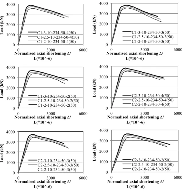
4.3 Effect of Steel Wall Thickness on Ultimate Load Capacity
Figure 9 Effect of steel wall thickness on ultimate load capacity
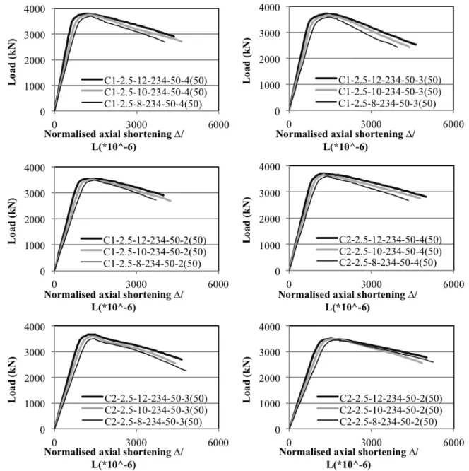
4.4 Effect of Diameter of Bar Stiffeners on Ultimate Load Capacity
Figure 10 Effect of diameter of bar stiffeners on ultimate load capacity
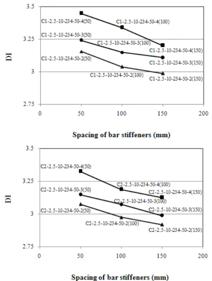
4.5 Effect of Number and Spacing of Bar Stiffeners on Ductility
In order to assess the ductility of the columns, a ductility index (DI) defined by Lin and Tsai [27] has been utilised in this paper. Equation (5) is the ductility index:
(5)
to the loadthatobtains 75% of the ultimate load capacity. The values of ε85% andεy can be taken from Figure 7. Effects of number and spacing of the bar stiffeners on the ductility are demonstrated in Figure
11.
Figure 11 Effects of number and spacing of bar stiffeners on ductility
The ductility of the unstiffened column can be determined as 2.85 from Figure 4 and using Equation (5). The use of 4C1 bar stiffeners (C1-2.5-10-234-50-4(50)) and 4C2 bar stiffeners (C2-2.5-10-234-50-4(50)) in the unstiffened column improves the ductility of the column from 2.85 to 3.447 and 3.325 (Figure 11) respectively, which represent the maximum ductility increases of 20.9% and 16.7%, re-spectively.
On the other hand, as the number of the bar stiffeners increases the ductility of the columns enhances (Figure 11). For example, by the increase of the number of the bar stiffeners from 2 to 4 for the same bar stiffeners spacing of 100 mm, the ductility improves from 2.974 (C2-2.5-10-234-50-2(100)) to 3.187 (C2-2.5-10-234-50-4(100)), an improvement of 7.2%.
3.325 (C2-2.5-10-234-50-4(50)) respectively for the stiffeners spacing of 150 mm and 50 mm, an en-hancement of 6.4%.
4.6 Effects of Thickness of Steel Wall on Ductility
Equation (5) of the section 4.5 has been also used to evaluate the effect of steel wall thickness on the ductility of the columns. Figure 12 indicates this effect on the ductility of the columns. The ductility is improved by the increase of the steel wall thickness (Figure 12). As an example, the enhancement of the steel wall thickness from 2 mm to 3 mm enhances the ductility of the column C2-2-10-234-50-2(50) from 2.979 to 3.225 (C2-3-10-234-50-2(50)), an improvement of 8.3%.
Figure 12 Effect of thickness of steel wall on ductility 4.7 Effect of Load Eccentricity on Ultimate Load Capacity
Figure 13 Effect of load eccentricity on ultimate load capacity
4.8 Effect of Concrete Compressive Strength on Ultimate Load Capacity
Figure 14 Effect of concrete compressive strength on ultimate load capacity
4.9 Effect of Steel Yield Stress on Ultimate Load Capacity
Figure 15 Effect of steel yield stress on ultimate load capacity 4.10 Ultimate load capacity prediction
Typical failure modes of the stiffened CFSC stub columns are illustrated in Figures 16 and 17. As can be seen from the figures, the failure modes of the columns were identified as concrete crushing about their mid-height where local buckling of the steel wall was induced. Also, the in-filled concrete prevented the steel wall from the buckling inward.
con-finement effect delays the local buckling of the steel wall which leads to the increase of the ultimate load capacity and ductility.
a b c
Figure 16 Typical failure modes of the stiffened CFSC stub columns with C1 bar stiffener: (a) 2 bar stiffeners with spacing of 50 mm, (b) 3 bar stiffeners with spacing of 100 mm, (c) 4 bar stiffeners with spacing of 150 mm
Figure 17 Typical failure modes of the stiffened CFSC stub columns with C2 bar stiffener: (a) 2 bar stiffeners with spacing of 50 mm, (b) 3 bar stiffeners with spacing of 100 mm, (c) 4 bar stiffeners with spacing of 150 mm
4.11 Failure Modes of Stiffened CFSC Columns
EC4 [11] is one of the popular international standards in composite construction which is used throughout the world. According to EC4 [11], the ultimate load capacity of a square or rectangular CFSC stub column can be calculated from Equation (6):
Npl,Rd = Aa fyd + Ac fcd (6)
On the other hand, Baig et al. [2] suggested an equation for calculating the ultimate load capacity of the columns as follows:
Pu = 1.10Acfc + Aa fy (7)
in which Ac and Aa are cross-sectional areas of concrete and steel respectively, and also fc and fy are compressive strength of the concrete core and yield stress of the steel wall, respectively. Ultimate load capacities predicted by Equation (7) are summarised in Table 2 and compared with those values achieved from the analyses. As can be seen from the table, a mean ratio (Pu/Nu) of 1.030 is achieved with a COV of 0.039 which indicates that Equation (7) overestimates the ultimate load capacity by 3%.
Based on the obtained results summarised in Table 1 and the equation of the EC4 [11], Equation (6), an equation is also proposed for prediction of the ultimate load capacity of the stiffened CFSC stub col-umns in this study, as following:
NB = Aa fyd +1.05Ac fcd (8)
Predicted ultimate load capacities based on the proposed equation, Equation (8), are listed in Table 2 and compared with the ultimate load capacity values obtained from the analyses. According to the ta-ble, a mean ratio (NB/Nu) of 0.992 is accomplished with a COV of 0.038 which demonstrates that Equa-tion (8) gives the ultimate load capacity by only 0.8% lower than the results obtained from the nonline-ar analyses. Therefore, the proposed equation of this study can give a very close prediction of the ulti-mate load capacity of the columns.
It is worth mentioning that ultimate load capacity predictions for eccentrically loaded columns can be done using Equations (6), (7), and (8) and the interaction curve (Figure 6.19 of EC4 [11]). These predictions based on the above-mentioned procedure for eccentrically loaded columns have been also summarised in Table 2.
Table 2 Comparison of obtained ultimate load capacity values (Nu) with predictions by EC4 [11] (Npl,Rd), equation of Baig et al. [2] (Pu), and proposed equation (NB)
No. Column label Nu
(kN)
Npl,Rd (kN)
Npl,Rd/Nu Pu (kN)
Pu/Nu NB (kN)
NB/Nu
1 C1-2.5-10-234-50-4(50) 3760 3409 0.907 3728 0.991 3584 0.953
2 C1-2.5-10-234-50-3(50) 3661 3409 0.931 3728 1.018 3584 0.979
3 C1-2.5-10-234-50-2(50) 3517 3409 0.969 3728 1.060 3584 1.019
4 C1-2.5-10-234-50-4(100) 3656 3409 0.932 3728 1.020 3584 0.980
5 C1-2.5-10-234-50-3(100) 3557 3409 0.958 3728 1.048 3584 1.008
7 C1-2.5-10-234-50-4(150) 3579 3409 0.953 3728 1.042 3584 1.001
8 C1-2.5-10-234-50-3(150) 3486 3409 0.978 3728 1.069 3584 1.028
9 C1-2.5-10-234-50-2(150) 3359 3409 1.015 3728 1.110 3584 1.067
10 C2-2.5-10-234-50-4(50) 3668 3409 0.929 3728 1.016 3584 0.977
11 C2-2.5-10-234-50-3(50) 3583 3409 0.951 3728 1.040 3584 1.000
12 C2-2.5-10-234-50-2(50) 3473 3409 0.982 3728 1.073 3584 1.032
13 C2-2.5-10-234-50-4(100) 3575 3409 0.954 3728 1.043 3584 1.003
14 C2-2.5-10-234-50-3(100) 3499 3409 0.974 3728 1.065 3584 1.024
15 C2-2.5-10-234-50-2(100) 3398 3409 1.003 3728 1.097 3584 1.055
16 C2-2.5-10-234-50-4(150) 3510 3409 0.971 3728 1.062 3584 1.021
17 C2-2.5-10-234-50-3(150) 3445 3409 0.990 3728 1.082 3584 1.040
18 C2-2.5-10-234-50-2(150) 3348 3409 1.018 3728 1.113 3584 1.071
19 C1-3-10-234-50-4(50) 3905 3499 0.896 3782 0.969 3641 0.932
20 C1-2-10-234-50-4(50) 3596 3380 0.940 3672 1.021 3526 0.981
21 C1-3-10-234-50-3(50) 3793 3499 0.922 3782 0.997 3641 0.960
22 C1-2-10-234-50-3(50) 3525 3380 0.959 3672 1.042 3526 1.000
23 C1-3-10-234-50-2(50) 3665 3499 0.955 3782 1.032 3641 0.993
24 C1-2-10-234-50-2(50) 3368 3380 1.004 3672 1.090 3526 1.047
25 C2-3-10-234-50-4(50) 3825 3499 0.915 3782 0.989 3641 0.952
26 C2-2-10-234-50-4(50) 3516 3380 0.961 3672 1.045 3526 1.003
27 C2-3-10-234-50-3(50) 3732 3499 0.938 3782 1.013 3641 0.975
Table 2 continued
No. Column label Nu
(kN)
Npl,Rd (kN)
Npl,Rd/Nu Pu (kN)
Pu/Nu NB (kN)
NB/Nu
28 C2-2-10-234-50-3(50) 3437 3380 0.983 3672 1.069 3526 1.026
29 C2-3-10-234-50-2(50) 3622 3499 0.966 3782 1.044 3641 1.005
30 C2-2-10-234-50-2(50) 3320 3380 1.018 3672 1.106 3526 1.062
31 C1-2.5-12-234-50-4(50) 3804 3409 0.896 3728 0.980 3584 0.942
32 C1-2.5-8-234-50-4(50) 3695 3409 0.923 3728 1.009 3584 0.970
33 C1-2.5-12-234-50-3(50) 3721 3409 0.916 3728 1.002 3584 0.963
35 C1-2.5-12-234-50-2(50) 3544 3409 0.962 3728 1.052 3584 1.011
36 C1-2.5-8-234-50-2(50) 3486 3409 0.978 3728 1.069 3584 1.028
37 C2-2.5-12-234-50-4(50) 3719 3409 0.917 3728 1.002 3584 0.964
38 C2-2.5-8-234-50-4(50) 3622 3409 0.941 3728 1.029 3584 0.990
39 C2-2.5-12-234-50-3(50) 3661 3409 0.931 3728 1.018 3584 0.979
40 C2-2.5-8-234-50-3(50) 3505 3409 0.973 3728 1.064 3584 1.023
41 C2-2.5-12-234-50-2(50) 3506 3409 0.972 3728 1.063 3584 1.022
42 C2-2.5-8-234-50-2(50) 3438 3409 0.992 3728 1.084 3584 1.042
43 C1-2.5-10-234-50-4(50)-30 3086 2731 0.885 2935 0.951 2834 0.918
44 C1-2.5-10-234-50-4(50)-60 2425 2114 0.872 2262 0.933 2185 0.901
45 C1-2.5-10-234-50-4(100)-30 2926 2671 0.913 2858 0.977 2759 0.943
46 C1-2.5-10-234-50-4(100)-60 2225 1996 0.897 2125 0.955 2053 0.923
47 C1-2.5-10-234-40-4(50) 3138 2860 0.911 3090 0.985 2975 0.948
48 C1-2.5-10-234-30-4(50) 2520 2285 0.907 2458 0.975 2371 0.941
49 C1-2.5-10-234-40-3(50) 3063 2860 0.934 3090 1.009 2975 0.971
50 C1-2.5-10-234-30-3(50) 2449 2285 0.933 2458 1.004 2371 0.968
51 C1-2.5-10-234-40-2(50) 2942 2860 0.972 3090 1.050 2975 1.011
52 C1-2.5-10-234-30-2(50) 2347 2285 0.974 2458 1.047 2371 1.010
53 C2-2.5-10-234-40-4(50) 3077 2860 0.929 3090 1.004 2975 0.967
54 C2-2.5-10-234-30-4(50) 2468 2285 0.926 2458 0.996 2371 0.961
55 C2-2.5-10-234-40-3(50) 3021 2860 0.947 3090 1.023 2975 0.985
56 C2-2.5-10-234-30-3(50) 2446 2285 0.934 2458 1.005 2371 0.970
57 C2-2.5-10-234-40-2(50) 2909 2860 0.983 3090 1.062 2975 1.023
58 C2-2.5-10-234-30-2(50) 2329 2285 0.981 2458 1.055 2371 1.018
Table 2 continued
No. Column label Nu
(kN)
Npl,Rd
(kN)
Npl,Rd/Nu Pu
(kN)
Pu/Nu NB
(kN)
NB/Nu
59 C1-2.5-10-450-50-4(50) 4375 3957 0.904 4245 0.970 4101 0.937
60 C1-2.5-10-350-50-4(50) 4102 3717 0.906 4005 0.976 3861 0.941
61 C1-2.5-10-450-50-3(50) 4219 3957 0.938 4245 1.006 4101 0.972
62 C1-2.5-10-350-50-3(50) 3976 3717 0.935 4005 1.007 3861 0.971
63 C1-2.5-10-450-50-2(50) 4067 3957 0.973 4245 1.044 4101 1.008
64 C1-2.5-10-350-50-2(50) 3853 3717 0.965 4005 1.040 3861 1.002
66 C2-2.5-10-350-50-4(50) 4011 3717 0.927 4005 0.999 3861 0.963
67 C2-2.5-10-450-50-3(50) 4104 3957 0.964 4245 1.034 4101 0.999
68 C2-2.5-10-350-50-3(50) 3906 3717 0.952 4005 1.025 3861 0.989
69 C2-2.5-10-450-50-2(50) 4042 3957 0.979 4245 1.050 4101 1.015
70 C2-2.5-10-350-50-2(50) 3807 3717 0.976 4005 1.052 3861 1.014
Mean 0.949 1.030 0.992
SD 0.033 0.040 0.037
COV 0.035 0.039 0.038
5 CONCLUSIONS
Behaviour of stiffened concrete-filled steel composite (CFSC) stub columns subjected to axial loading has been studied in this paper. The finite element software LUSAS was employed to carry out the non-linear finite element analyses. Accuracy of the proposed 3D finite element modelling was demonstrated by comparison of the modelling result with the corresponding experimental result. It was uncovered that the proposed modelling can predict the behaviour of the columns accurately. The CFSC stub col-umns were extensively developed utilising different special arrangements, number, spacing, and diam-eters of bar stiffeners with various steel wall thicknesses, concrete compressive strengths, and steel yield stresses. It was shown that by the use of C1 and C2 bar stiffeners the ultimate load capacity and ductility of the columns are increased. Increasing number of the bar stiffeners and/or steel wall thick-ness enhances the ultimate load capacity and ductility of the columns. The increase of the diameter of the bar stiffeners increases the ultimate load capacity. As spacing of the bar stiffeners decreases the ultimate load capacity and ductility are improved. The use of the bar stiffeners, increase of the number of the bar stiffeners, decrease of spacing of the bar stiffeners, enhancement of the steel wall thickness, or increase of diameter of the bar stiffeners enhances the confinement effect of the steel wall on the concrete core and delays the local buckling of the steel wall which leads to the increased ultimate load capacity and ductility. Enhancement of the load eccentricity decreases the ultimate load capacity of the columns. Also, if the concrete compressive strength is enhanced, the ultimate load capacity is increased because the use of higher concrete compressive strength significantly increases the bond strength of the columns with the stiffeners. Moreover, the higher steel yield stress results in higher ultimate load capacity. The improved ultimate load capacity of the columns owing to the increase of the concrete compressive strength and/or steel yield stress of the columns leads to utilising smaller column size and enhancing the usable floor space in a structure. The smaller size of CFSC columns results in more sav-ings in weight and material of the structure. Meanwhile, the columns failed due to concrete crushing about their mid-height where the steel wall locally buckled. The inward buckling of the steel wall was prevented by the in-filled concrete. Based on the obtained results, an equation was also proposed to predict the ultimate load capacity of the columns. Furthermore, the ultimate load capacities of the col-umns were predicted based on EC4 [11], the equation of Baig et al. [2] and the proposed equation of this study and also compared with those obtained values from the nonlinear analyses. These compari-sons revealed that the equations of EC4 [11] and Baig et al. [2] could respectively estimate the ultimate load capacities with 5.1% underestimation and 3% overestimation. On the other hand, the comparisons demonstrated that the proposed equation of this study could give a very close prediction of the ultimate load capacities with only 0.8% underestimation.
[1] A. Bahrami, W.H. Wan Badaruzzaman and S.A. Osman. Nonlinear analysis of concrete-filled steel composite col-umns subjected to axial loading. Structural Engineering and Mechanics-An International Journal, 39(3):383-398, 2011.
[2] M.N. Baig, F. Jiansheng and N. Jianguo. Strength of concrete filled steel tubular columns. Tsinghua Science and Technology, 11(6):657-666, 2006.
[3] C.G. Bailey. Fire engineering design of steel structures. Advances in Structural Engineering, 8(3): 185–202, 2005. [4] M.A. Dabaon, M.H. El-Boghdadi and M.F. Hassanein. Experimental investigation on concrete-filled stainless steel
stiffened tubular stub columns. Engineering Structures, 31:300-307, 2009.
[5] M. Dabaon, S. El-Khoriby, M. El-Boghdadi and M.F. Hassanein. Confinement effect of stiffened and unstiffened concrete-filled stainless steel tubular stub columns. Journal of Constructional Steel Research, 65:1846-1854, 2009.
[6] X.H. Dai and D. Lam. Shape effect on the behaviour of axially loaded concrete filled steel tubular stub columns at elevated temperature. Journal of Constructional Steel Research, 73:117–127, 2012.
[7] E. Ellobody and B. Young. Design and behaviour of concrete-filled cold-formed stainless steel tube columns. Engi-neering Structures, 28:716-728, 2006a.
[8] E. Ellobody and B. Young. Nonlinear analysis of concrete-filled steel SHS and RHS columns. Thin-Walled Struc-tures, 44:919–930, 2006b.
[9] E. Ellobody, B. Young and D. Lam. Behaviour of normal and high strength concrete-filled compact steel tube circu-lar stub columns. Journal of Constructional Steel Research, 62(7):706-715, 2006.
[10] A. Elremaily and A. Azizinamini. Behavior and strength of circular concrete-filled tube columns. Journal of Con-structional Steel Research, 58:1567-1591, 2002.
[11] Eurocode 4, BS EN 1994-1-1. Design of composite steel and concrete structures- Part 1-1: General rules and rules for buildings. London: British Standard Institution, 2004.
[12] Finite Element Analysis Ltd., LUSAS User’s Manual, Version 14, Surrey, UK, 2006.
[13] G. Giakoumelis and D. Lam. Axial capacity of circular concrete-filled tube columns. Journal of Constructional Steel Research, 60(7):1049–1068, 2004.
[14] C.D. Goode and D. Lam. Concrete-filled steel tube columns–tests compared with Eurocode 4. Proceedings of the international conference on composite construction VI, Devil's Thumb Ranch, Colorado, USA, July 20-24, 2008. [15] L.H. Han, W. Liu and Y.F. Yang. Behaviour of concrete-filled steel tubular stub columns subjected to axially local
compression. Journal of Constructional Steel Research, 64:377-387, 2008.
[16] L.H. Han, Y.F. Yang and L. Xu. An experimental study and calculation on the fire resistance of concrete-filled SHS and RHS columns. Journal of Constructional Steel Research, 59:427–452, 2003.
[17] L.H. Han, G.H. Yao and X.L. Zhao. Tests and calculations for hollow structural steel (HSS) stub columns filled with self-consolidating concrete (SCC). Journal of Constructional Steel Research, 61:1241-1269, 2005.
[18] L.H. Han, X.L. Zhao, Y.F. Yang and J.B. Feng. Experimental study and calculation of fire resistance of concrete-filled hollow steel columns, Journal of Structural Engineering, ASCE, 129(3):346-356, 2003.
[19] H.T. Hu, C.S. Huang and Z.L. Chen. Finite element analysis of CFT columns subjected to an axial compressive force and bending moment in combination. Journal of Constructional Steel Research, 61:1692–1712, 2005.
[20] H.T. Hu, C.S. Huang, M.H. Wu and Y.M. Wu. Nonlinear analysis of axially loaded concrete-filled tube columns with confinement effect. Journal of Structural Engineering ASCE, 129(10):1322–1329, 2003.
[21] H.T. Hu and W.C. Schnobrich. Constitutive modeling of concrete by using nonassociated plasticity. Journal of Materials in Civil Engineering, 1(4):199–216, 1989.
[22] V.K.R. Kodur. Performance of high strength concrete-filled steel columns exposed to fire. Canadian Journal of Civil Engineering, 25:975-981, 1998.
[23] V.K.R. Kodur, F.P. Cheng, T.C. Wang and M.A. Sultan. Effect of strength and fibre reinforcement on fire resistance of high-strength concrete columns. Journal of Structural Engineering, ASCE, 129(2):253-259, 2003.
[24] D. Lam and L. Gardner. Structural design of stainless steel concrete filled columns. Journal of Constructional Steel Research, 64(11):1275-1282, 2008.
[25] T.T. Lie and V.K.R. Kodur. Fire resistance of steel columns filled bar-reinforced concrete. Journal of Structural Engineering, ASCE, 122(1):30-36, 1996.
[26] J.Y.R. Liew and D.X. Xiong. Effect of preload on the axial capacity of concrete-filled composite columns. Journal of Constructional Steel Research, 65:709-722, 2009.
[27] M.L. Lin and K.C. Tsai. Behaviour of double-skinned composite steel tubular columns subjected to combined axial and flexural loads. Proceedings of the first international conference on the steel & composite structures. Pusan, Korea, 1145-1152, 2001.
[29] H. Lua, X.L. Zhaoa and L.H. Han. Testing of self-consolidating concrete-filled double skin tubular stub columns exposed to fire, Journal of Constructional Steel Research, 66:1069-1080, 2010.
[30] J.B. Mander, M.J.N. Priestley and R. Park. Theoretical stress–strain model for confined concrete. Journal of Struc-tural Engineering ASCE, 114(8):1804-1826, 1988.
[31] M.A. Mansur, M.S. Chin and T.H. Wee. Stress-strain relationship of high-strength fiber concrete in compression. Journal of Materials in Civil Engineering, 11(1):21-29, 1999.
[32] S. Morino and K. Tsuda. Design and construction of concrete-filled steel tube column system in Japan. Earthquake Engineering and Engineering Seismology, 4(1): 51-73, 2003.
[33] G. Muciaccia, F. Giussani, G. Rosati and F. Mola. Response of self-compacting concrete filled tubes under eccentric compression. Journal of Constructional Steel Research, 67:904-916, 2011.
[34] M. Mursi. The behaviour and design of thin walled concrete filled steel box columns. Ph.D. Thesis. School of Civil and Environmental Engineering, The University of New South Wales, Sydney, Australia, 2007.
[35] M. Mursi and B. Uy. Strength of concrete filled steel box columns incorporating interaction buckling. Journal of Structural Engineering ASCE, 129(5): 626–639, 2003.
[36] W.L.A. Oliveira, S. De Nardin, A.L.H.C. El Debs and M.K. El Debs. Evaluation of passive confinement in CFT columns. Journal of Constructional Steel Research, 66:487-495, 2010.
[37] F.E. Richart, A. Brandzaeg and R.L. Brown. A study of the failure of concrete under combined compressive stress-es. Bull. 185, Champaign, IL, USA: University of Illinois Engineering Experimental Station, 1928.
[38] M.L. Romero, V. Moliner, A. Espinos, C. Ibañez and A. Hospitaler. Fire behavior of axially loaded slender high strength concrete-filled tubular columns, Journal of Constructional Steel Research, 67: 1953–1965, 2011. [39] L.P. Saenz. Discussion of "Equation for the stress–strain curve of concrete" by P. Desayi and S. Krishnan, Journal of
the American Concrete Institute, 61(3):1229–1235, 1964.
[40] P. Schaumann, V.K.R. Kodur and O. Bahr. Fire behaviour of hollow structural section steel columns filled with high strength concrete, Journal of Constructional Steel Research, 65:1794-1802, 2009.
[41] Z. Tao, L.H. Han and D.Y. Wang. Experimental behaviour of concrete-filled stiffened thin-walled steel tubular columns. Thin-Walled Structures, 45:517-527, 2007.
[42] Z. Tao, L.H. Han and Z.B. Wang. Experimental behaviour of stiffened concrete-filled thin-walled hollow steel struc-tural (HSS) stub columns. Journal of Constructional Steel Research, 61:962-983, 2005.
[43] Z. Tao, B. Uy, L.H. Han and Z.B. Wang. Analysis and design of concrete-filled stiffened thin-walled steel tubular columns under axial compression. Thin-Walled Structures, 47: 1544-1556, 2009.
[44] M. Tomii. Ductile and strong columns composed of steel tube infilled concrete and longitudinal steel bars. Special volume, Proceedings of the third international conference on steel–concrete composite structures. Fukuoka, Ja-pan: Association of Steel-Concrete Structures, 1991.
[45] K. Uenaka, H. Kitoh and K. Sonoda. Concrete filled double skin circular stub columns under compression. Thin-Walled Structures, 48:19-24, 2010.
[46] B. Uy and S.B. Patil. Concrete-filled high strength steel box columns for tall buildings: behaviour and design. Struc-tural Design of Tall Buildings, 5:75–94, 1996.