Abstract— An alternative method is proposed to characterize the radiation pattern of antennas from an impulse response, based on a moment expansion together with a frequency domain near-to-far-field transformation via a FDTD/CPML solver. The approach introduced in the present work is intended for printed antenna analysis in special cases when the geometries to be modeled require a high degree of discretization in the space-time domain, which directly affects the frequency resolution when using FFT to perform the conventional NF-FF techniques. Results are compared with those obtained by a reference frequency-domain NF-FF technique and the applicability of the proposed method is demonstrated.
Index Terms— Finite-difference time-domain method, time-domain moment expansion, near-to-far-field transformation.
I. INTRODUCTION
The finite-difference time-domain (FDTD) method in addition to absorbing boundary conditions
and perfect matched layers (PML) has been successfully used in the analysis of radiation and
scattering problems [1]. FDTD is very efficient when making near field calculations, while for the far
field it is necessary to use an additional method to perform a near-to-far-field (NF-FF) transformation.
The first technique used to perform the NF-FF transformation could only be applied to a single
frequency analysis [1], [3]. In order to obtain a broader frequency bandwidth response, a broadband
excitation followed by a discrete Fourier transform was performed [1], [4]. Recently, methods
involving a recursive addition of tangential field contribution over a virtual equivalent surface have
been used to perform the same task [5]-[8]. There are basically two different methods to perform a
NF-FF transformation [4]. In the first approach the time-domain near electromagnetic fields over a
virtual surface were obtained, followed by the calculation of the equivalent currents, and the
calculation of the time-domain electromagnetic far fields with a time-domain NF-FF transformation.
This procedure is adopted when broadband results are required. In the second method FFT is applied
to the FDTD electromagnetic near fields. Therefore the equivalent currents are calculated in
frequency-domain and the result is used to compute the far fields via a frequency-domain NF-FF
transformation. This procedure is suited for the analysis of narrowband antennas. Conventional
time-Characterization of the Radiation Pattern of
Antennas via FDTD and Time-Domain
Moment Expansion
Glaucio L. Ramos 1 and Cássio G. Rego 2 1
Federal University of São João del-Rei, Department of Telecommunications and Mechatronics Engineering, Ouro Branco, MG, [email protected] 2
domain NF-FF transformation techniques [1], [4], where time-domain far fields can be directly
obtained, are based on the retarded potential method and as consequence, a new integration over the
near-field is necessary for each observation point [6], [9]. Therefore, when broadband results are
required at a large number of observation angles, as in the case with radiation patterns, these
techniques require a larger amount of computational resources [4].
Here an alternative method is proposed, based on frequency domain NF-FF transformation together
with moment expansion of a Gaussian pulse to characterize the radiation patterns of wideband
antennas. The method is intended for printed antenna analysis, in special cases when the geometries to
be modeled on FDTD Yee cells require a high degree of discretization in the space-time domain,
which directly affects the frequency resolution when using FFT to perform the frequency-domain
NF-FF transformation. The proposed moment expansion allows us to estimate, for a single frequency, the
equivalent near fields on a Huygens surface before being applied to the near-to-far-field
transformation. Therefore, the frequency-domain NF-FF allow us to calculate the radiation pattern of
a broadband antenna for a large frequency band. Also it is an alternative technique to obtain the
frequency-domain radiation pattern for broadband antennas without the need to perform costly
time-domain numerical computation [9], [10].
This paper is organized as follows: Section II gives a brief description of the frequency-domain
near-to-far-field transformation. In Section III, the radiation patterns obtained from two UWB
antennas are presented and compared to results from the time-domain moment expansion technique.
II. FORMULATIONOFTHEFREQUENCYDOMAINNEAR-TO-FAR-FIELD TRANSFORMATION
To perform the frequency-domain near-to-far-field transformation, the field components on a
Huygens surface are replaced by equivalent electric and magnetic dipoles [11], allowing the
calculation of the equivalent surface currents moments by using FDTD near fields. Once the surface
current moments are determined, the vector potentialA
and F
are used to calculate the radiation farfields [11]. Here we suggest an alternative approach to perform the near-to-far-field transformation by
the use of a moment expansion process, which uses a fourth order approximation to estimate the near
fields from its impulse response [12].
When performing antenna analysis via a FDTD it is necessary to minimize numerical dispersion.
The number of chosen points per wavelength for the cell size is dependent on many factors, but a
good rule of thumb is 10 points per wavelength [1]. In order to avoid numerical instability the time
step must also be selected as
t/
c3
, where x y z and cis the speed of light at vacuum [1]. The use of the previous space discretization leads to a FDTD time step of/ (10
3)
t
cis fmax
1
/
2
t
5
c3
/
, and using N time samples, the frequency resolution after the FFT process is fmax/
N. When using FDTD to analyze some special cases of printed antenna geometries it is necessary to perform a degree of space discretization significantly higher than the minimumnecessary to minimize numerical dispersion, in order to make a proper antenna modeling. This leads
to a decrease in the FFT frequency resolution and thus has an impact on the results obtained from the
frequency domain radiation pattern of these kinds of antennas and suggests the use of the moment
expansion technique in order to improve the accuracy of the results.
It was also shown that as a Gaussian pulse is band-limited, the computation of the
frequency-domain near fields in the FDTD solver is less accurate outside a frequency band depending on the
chosen computational parameters [13]. As a consequence, the moment expansion technique with
fourth-order truncation has been shown to improve accuracy and computational efficiency when using
Gaussian pulse excitation as compared with the Fourier transform, especially when the upper
frequency of the impulse response is greater than its upper (10% amplitude) frequency [12]-[14]. The
parameters used for the impulse response retrieval via FDTD and moment expansion deconvolution
technique may be fmaxFDTD 1.5fm, where fmaxFDTD c n
, n may be in the range {8-10}, is the largestFDTD cell size and fm is the highest frequency to be computed. The Gaussian-pulse parameters may also be such that its 10% amplitude upper frequency fG may be in the range of
[1.5
,
maxFDTD]
m
f f [12].
III. MOMENT EXPANSION OF TIME FUNCTIONS AND IMPULSE RESPONSE
The impulse response of an antenna can be obtained by an inverse Fourier transform in a
deconvolution process. It can be also be obtained directly from an arbitrary time response of the
antenna under analysis, by a moment expansion of a signal in the time domain [14]. Considering a
circuit excited at a port i with a signal v ti
( )
and the associated response, v tk( )
, at a port k, the followed relation is valid
0
( ) ( ) ( ) ( ),
t
k ik i ik i
v t
h t
v d h t v t (1)where h tik
( )
is the impulse response between k and i ports written as1
( )
( )
,
( )
k ik
i
V h t
V
(2)with
1 being the inverse Fourier transform, Vi( )
v ti( )
, and Vk( )
v tk( )
. The impulse response h tik( )
can be obtained by FDTD using a Fourier process for the samples v n ti(
)
and v n tk(
)
, or the integral equation as in [14].0 0
1
(
) ,
( )
!
N l l j t l i a jV
e
l
(3) where t0 and the coefficients al are obtained by the moments
m of the time signal v ti( )
:0 0
(
)
(
)
1,
!
!
N N l m l m l m a j j l m
(4)with
( ) ( )
0 0
0
(
)
( )
(
)
(0),
m
m m p p p
m i i
p
m
t t v t dt t j V
p
(5)and ( ) 0
( )
(0)
,
p p i i p d V V d
(6)(1)
0 (2) (1)
(0) /
(0), non-zero average
.
(0) /
(0), zero average
i i i i jV V t jV V
(7)Using the moment expansion, the impulse response as in (2) can be written as:
1 0 0
(
)
(
)
( ) ,
!
N l l ik k l ah t t j V
l
(8)or, for v ti
( )
with non-zero average:0 0 2
( )
(
),
!
l N lik l k
l
a d
h t a v t t
l dt
(9)or, for the zero average case:
0 ( 1)
0 ( 1) 0
2 0
( ) ( ).
!
t t N l l
ik l k
l
a d
h t a d v t t
l dt
(10)In this work the input signal for the antenna under analysis was the gaussian pulse in the form of
2 0 2 0 2 ) ( ) ( T t i t e
v
. (11) Using the FDTD time increment t n t, n0,1, , and for a Gaussian pulse excitation in the
form of (11) we can use a fourth order approximation for the input i and output port k leading to an
impulse response between these ports hik as [14]
4 0 0 4 2 4 0 0 2 4 2 40 2 4 0
2
2
24
1
1
2
6
,
4
ik k k
k k
k
a
h n v n n v n n
t
a a
v n n v n n
t t
a a
a v n n
where the parameters a0, a2, a4 and n0 are
0
0 2 2 0 0
4 4 0 0
0 0
1
,
2
,
3
,
int
,
a
T
a a T
a a T
t n
t
(13)
and the shift parametert0
jV(1)
0 /
V0
, with ( )
0
0
p i p
i p
d V V
d
, is chosen as [14].
The moment expansion technique was applied to the antenna problem analysis in such a manner
that vi
(t
)
is the antenna pulse excitation and vk(t
)
is each near field component on a virtual surfacesurrounding the antenna. The impulse response is then estimated for each near field component and
after the convolution process each near field component is properly replaced as an input to the NF-FF
transformation.
IV. NUMERICAL RESULTS
The moment expansion and frequency-domain near-to-far-field techniques were applied to two
UWB patch antennas in order to obtain their radiation pattern [15], [16].
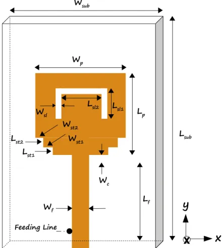
The patch antenna dimensions for the geometry of Figure 2 are Lsub = 35 mm, Wsub = 30 mm,
Lf = 12.5 mm, Wf = 3.2 mm, Lp = 14.5 mm, Wp = 15 mm, Wc = 1 mm, Lst1 = 1 mm, Wst1 = 1.5 mm,
Lst2 = 1.5 mm, Wst2 = 1.5 mm, Lsl1 = 5 mm, Lsl2 = 7 mm and Wsl = 0.5 mm. This UWB antenna also
has a 1.6 mm thick FR4 dielectric substrate, on a z-plane, with a relative permittivity of
r = 4.4. The antenna dimensions correspond to 140 × 120 × 3 FDTD cells, at x, y and z direction, respectively. Toobtain the radiation pattern of the antenna under simulation, a FDTD/CPML reference code was
obtained [3] and the full domain of the FDTD solver has 200 × 180 × 63 cells. It was also performed
2000 FDTD time iterations.
Considering the minimum FDTD discretization to minimize numerical dispersion, 3 mm, and
instability, t5.7735ps, the frequency resolution obtained at FFT procedure should be
approximately 43.3 MHz. However, due to antenna dimensions the parameters used at simulation was
mm 25 . 0
and t 0.385ps - a FDTD time step 15 times lower than the minimum. Thus the frequency resolution due to FFT was 650 MHz and the moment expansion was used to increase the
accuracy of the results for the radiation pattern of the antenna under analysis. From the previously
defined FDTD parameters, fm = 10 GHz is the highest frequency to be computed and 11
max 1.210 FDTD
f Hz, which follows the previously defined set of parameters that enables the use of
To include the moment expansion technique, the antenna was excited with a Gaussian pulse with
T0 = 0.125 ps and
0 = 0.796 ps, where its 10% amplitude upper frequency fG = 27.32 GHz is in therange [15 GHz, 57 GHz]. The proposed technique was performed according to the following steps:
the near field was obtained by the FDTD solver. Once the impulse response of the system was known,
a convolution with a sinusoidal carrier was performed and the near field was updated for the
frequency under analysis. Finally, the frequency-domain near-to-far-field transformation was carried
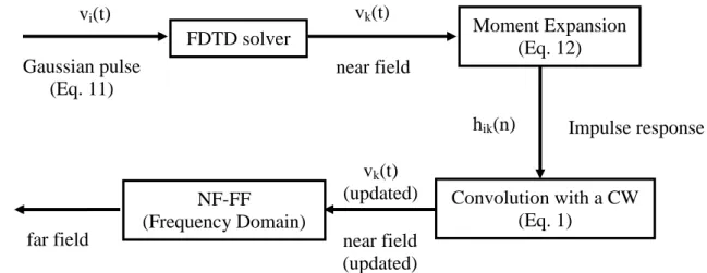
out yielding the radiation pattern. These steps are summarized in Fig. 1.
Fig. 1. Flow chart for the proposed technique.
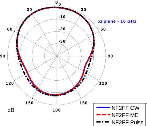
The radiation pattern of the UWB antenna under analysis was obtained by three different methods
applied to the FDTD/CPML code: a sinusoidal carrier at 10 GHz as input signal (NF2FF CW, used as
reference), a Gaussian pulse was used as input signal with the use of the moment expansion technique
(NF2FF ME) and the same Gaussian pulse as input signal with the conventional DFT procedure
(NF2FF Pulse). Figure 3 shows an excellent agreement between the proposed moment expansion
technique and the NF-FF technique with a sinusoidal input signal and this better result can be
explained by the convolution with a sinusoidal input source at the moment expansion process. The use
of the proposed frequency-domain near-to-far-field together with the moment expansion is shown to
be more numerically efficient than the conventional technique, when a Gaussian pulse is used as an
input signal to characterize antenna radiation patterns in the cases when the modeling process of the
antenna on FDTD Yee cells requires a high degree of space discretization.
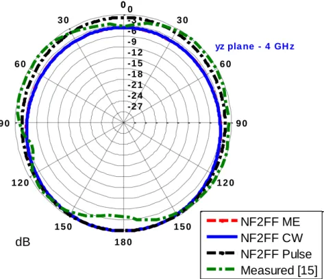
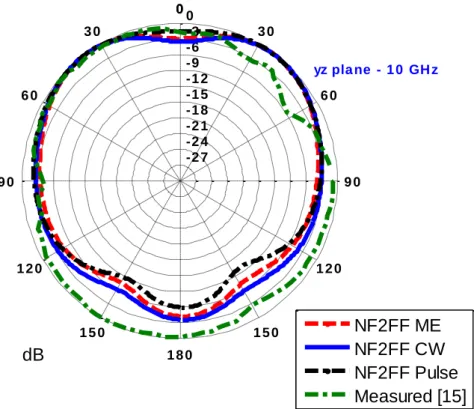
Radiation patterns of the UWB antenna for the x-y, x-z and y-z planes at 4, 7 and 10 GHz were
performed using the proposed moment expansion technique and compared with results obtained by a
carrier input signal for each frequency under analysis, as well as with measuments previously done
[15]. Results are shown in Figs. 3-11. These results show excellent agreement between the proposed
technique and previously obtained results [15]. These results also show that the proposed moment
expansion together with FDTD NF-FF solver, is able to efficiently calculate the radiation patterns in a
wide range of frequencies for these special cases of printed antennas. The results obtained are very
close to results from the reference single carrier excitation. Similar radiation patterns could be
FDTD solver
Moment Expansion
(Eq. 12)
Convolution with a CW
(Eq. 1)
NF-FF
(Frequency Domain)
Gaussian pulse
(Eq. 11)
v
i(t)
v
k(t)
near field
Impulse response
h
ik(n)
v
k(t)
(updated)
obtained by running the FDTD code for each frequency under analysis, but this method is not suitable
for computation. The method proposed here shows that even if there is a need to perform one more
step in characterizing the antenna radiation pattern, which is the convolution of the carrier frequency
with the obtained moment expansion impulse response, the additional step increases the accuracy of
numerical results without considerable increase to the computational effort. The differences between
the results obtained by simulation with the proposed technique and measurements previously done are
similar to the differences obtained when comparing the measurements with simulations obtained by a
commercial software and was explained by the effect of the feeding cables, the feeding connector and
the antenna fixation support [15].
The proposed technique was also applied to the antenna geometry of Figure 12. The antenna
dimensions are L = 33 mm, Wg = 30 mm, L1 = 16.5 mm, W1 = 12 mm, L2 = 4 mm, W2 = 3 mm, Gw1 =
1.5 mm, Lg = 15 mm, Lsc = 2.25 mm, Ls1 = 4 mm, Ws1 = 2.5 mm, Ls = 4 mm, and Ws = 0.3 mm. This
UWB antenna also has a 1.52 mm Taconic FR35 dielectric substrate, on a z-plane, with a relative
permittivity of
r = 3.5. The antenna dimensions correspond to 60 × 66 × 3 FDTD cells, at x, y and z direction, respectively. To obtain the radiation pattern of the antenna under simulation, aFDTD/CPML reference code was obtained [4] and the full domain of the FDTD solver has 100 × 106
× 43 cells. It was also performed 2000 FDTD time iterations.
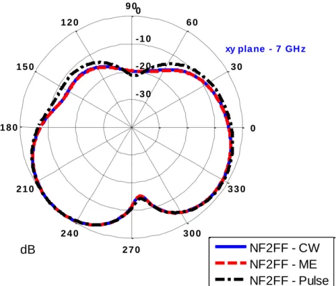
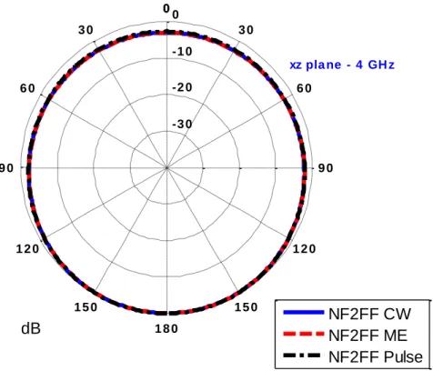
Radiation patterns of this UWB antenna for the x-y, x-z and y-z planes at 4, 7 and 10 GHz were
obtained and results are shown in Figs. 13-21. These results show once more that the proposed
moment expansion together with FDTD NF-FF solver, is able to efficiently calculate the radiation
patterns in a wide range of frequencies for these special cases of printed antennas.
V. CONCLUSION
In this research a moment expansion of time signals was proposed to obtain the impulse response of
some special cases of printed antennas and estimate the values of the near fields on a Huygens
equivalent surface for each frequency where the radiation pattern is to be characterized. These near
field estimated values were used together with a frequency-domain near-to-far-field transformation to
characterize the radiation pattern of an UWB printed antenna at three different frequency bands,
allowing the use of a frequency-domain NF-FF technique for wideband analysis.
The proposed technique is intended to printed antenna analysis for the special cases when the
geometries to be modeled require a high degree of space discretization. Since the conventional NF-FF
transformation are performed in frequency-domain, when using FDTD it is necessary FFT
computation. For these specific antennas, the high discretization makes the frequency resolution
coarser and the use of the moment expansion was used in order to increase the accuracy of the results
of the radiation patterns. The proposed methodology was applied to two different UWB antennas and
precise, thus validating the use of the proposed moment expansion based technique in performing
frequency-domain radiation patterns of antennas excited by a Gaussian pulse, even if there is an
additional step in characterizing the antenna radiation pattern as there is no significant increase in
computational effort.
When compared with conventional formulations, the proposed methodology has be shown to
improve the accuracy of frequency domain radiation pattern analysis, for these special cases of printed
antennas, as it permits a convolution with a sinusoidal input source, before the frequency domain
NF-FF is applied. For time domain NF-NF-FF, the moment expansion methodology has also been shown to
improve accuracy and computational efficiency when compared with conventional Fourier transform,
under the conditions mentioned before.
ACKNOWLEDGMENTS
This work was partially supported by CNPq, under Covenant 573939/2008-0 (INCT-CSF) and
Project 300938/2008-0, and Fapemig, under Projeto do Pesquisador Mineiro.
Wsub
Wf Lf
Lsub
Wp
Lst1
Lst2 Wst1
Wst2
Lsl1 Lsl2
Lp
Wc
Wsl
Feeding Line
x
x
y
-2 7 -2 4 -2 1 -1 8 -1 5 -1 2 -9 -6 -3 0
0 3 0 6 0
9 0 1 2 0
1 5 0
1 8 0
2 1 0
2 4 0
2 7 0
3 0 0
3 3 0
dB
xy pla ne - 4 GH z
NF2FF ME
NF2FF CW
NF2FF Pulse
Measured [15]
Fig. 3. Antenna 1: Radiation pattern in the x-y plane at 4 GHz.
-2 7 -2 4 -2 1 -1 8 -1 5 -1 2 -9 -6 -3 0
0 3 0 6 0
9 0 1 2 0
1 5 0
1 8 0
2 1 0
2 4 0
2 7 0
3 0 0
3 3 0
dB
xy pla ne - 7 GH z
NF2FF ME
NF2FF CW
NF2FF Pulse
Measured [15]
-2 7 -2 4 -2 1 -1 8 -1 5 -1 2 -9 -6 -3 0
0 3 0 6 0
9 0 1 2 0
1 5 0
1 8 0
2 1 0
2 4 0
2 7 0
3 0 0
3 3 0
dB
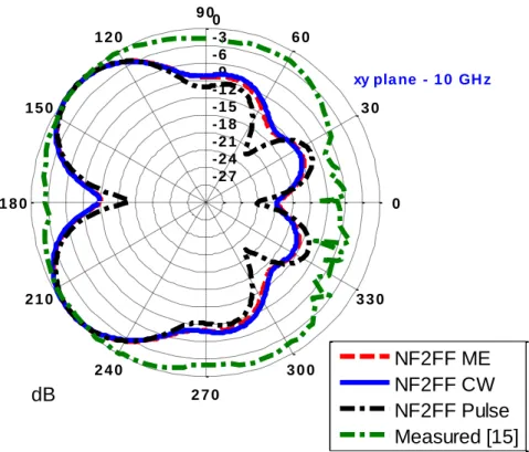
xy pla ne - 1 0 GH z
NF2FF ME
NF2FF CW
NF2FF Pulse
Measured [15]
Fig. 5. Antenna 1: Radiation pattern in the x-y plane at 10 GHz.
-2 7 -2 4 -2 1 -1 8 -1 5 -1 2 -9 -6 -3 0 0 0
3 0 3 0
6 0 6 0
9 0 9 0
1 2 0 1 2 0
1 5 0 1 5 0 1 8 0
dB
xz pla ne - 4 GH z
NF2FF ME
NF2FF CW
NF2FF Pulse
Measured [15]
-2 7 -2 4 -2 1 -1 8 -1 5 -1 2 -9 -6 -3 0 0 0
3 0 3 0
6 0 6 0
9 0 9 0
1 2 0 1 2 0
1 5 0 1 5 0 1 8 0
dB
x
xz pla ne - 7 GH z
NF2FF ME
NF2FF CW
NF2FF Pulse
Measured [15]
Fig. 7. Antenna 1: Radiation pattern in the x-z plane at 7 GHz.
-2 7 -2 4 -2 1 -1 8 -1 5 -1 2 -9 -6 -3 0 0 0
3 0 3 0
6 0 6 0
9 0 9 0
1 2 0 1 2 0
1 5 0 1 5 0 1 8 0
dB
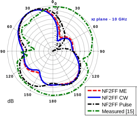
xz pla ne - 1 0 GH z
NF2FF ME
NF2FF CW
NF2FF Pulse
Measured [15]
-2 7 -2 4 -2 1 -1 8 -1 5 -1 2 -9 -6 -3 0 0 0
3 0 3 0
6 0 6 0
9 0 9 0
1 2 0 1 2 0
1 5 0 1 5 0 1 8 0
dB
yz pla ne - 4 GH z
NF2FF ME
NF2FF CW
NF2FF Pulse
Measured [15]
Fig. 9. Antenna 1: Radiation pattern in the y-z plane at 4 GHz.
-2 7 -2 4 -2 1 -1 8 -1 5 -1 2 -9 -6 -3 0 0 0
3 0 3 0
6 0 6 0
9 0 9 0
1 2 0 1 2 0
1 5 0 1 5 0 1 8 0
dB
yz pla ne - 7 GH z
NF2FF ME
NF2FF CW
NF2FF Pulse
Measured [15]
-2 7 -2 4 -2 1 -1 8 -1 5 -1 2 -9 -6 -3 0 0 0
3 0 3 0
6 0 6 0
9 0 9 0
1 2 0 1 2 0
1 5 0 1 5 0 1 8 0
dB
yz pla ne - 1 0 GH z
NF2FF ME
NF2FF CW
NF2FF Pulse
Measured [15]
Fig. 11. Antenna 1: Radiation pattern in the y-z plane at 10 GHz.
Fig. 12. UWB patch antenna: geometry 2.
x
x
-3 0 -2 0 -1 0 0
0 3 0 6 0
9 0 1 2 0
1 5 0
1 8 0
2 1 0
2 4 0
2 7 0
3 0 0
3 3 0
dB
xy pla ne - 4 GH z
NF2FF - CW
NF2FF - ME
NF2FF - Pulse
Fig. 13. Antenna 2: Radiation pattern in the x-y plane at 4 GHz.
-3 0 -2 0 -1 0 0
0 3 0 6 0
9 0 1 2 0
1 5 0
1 8 0
2 1 0
2 4 0
2 7 0
3 0 0
3 3 0
dB
xy pla ne - 7 GH z
NF2FF - CW
NF2FF - ME
NF2FF - Pulse
-3 0 -2 0 -1 0 0
0 3 0 6 0
9 0 1 2 0
1 5 0
1 8 0
2 1 0
2 4 0
2 7 0
3 0 0
3 3 0
dB
xy pla ne - 1 0 GH z
NF2FF - CW
NF2FF - ME
NF2FF - Pulse
Fig. 15. Antenna 2: Radiation pattern in the x-y plane at 10 GHz.
-3 0 -2 0 -1 0 0 0 0
3 0 3 0
6 0 6 0
9 0 9 0
1 2 0 1 2 0
1 5 0 1 5 0 1 8 0
dB
xz pla ne - 4 GH z
NF2FF CW
NF2FF ME
NF2FF Pulse
-3 0 -2 0 -1 0 0 0 0
3 0 3 0
6 0 6 0
9 0 9 0
1 2 0 1 2 0
1 5 0 1 5 0 1 8 0
dB
xz pla ne - 7 GH z
NF2FF CW
NF2FF ME
NF2FF Pulse
Fig. 17. Antenna 2: Radiation pattern in the x-z plane at 7 GHz.
-3 0 -2 0 -1 0 0 0 0
3 0 3 0
6 0 6 0
9 0 9 0
1 2 0 1 2 0
1 5 0 1 5 0 1 8 0
dB
xz pla ne - 1 0 GH z
NF2FF CW
NF2FF ME
NF2FF Pulse
-3 0 -2 0 -1 0 0 0 0
3 0 3 0
6 0 6 0
9 0 9 0
1 2 0 1 2 0
1 5 0 1 5 0 1 8 0
dB
yz pla ne - 4 GH z
NF2FF CW
NF2FF ME
NF2FF Pulse
Fig. 19. Antenna 2: Radiation pattern in the y-z plane at 4 GHz.
-3 0 -2 0 -1 0 0 0 0
3 0 3 0
6 0 6 0
9 0 9 0
1 2 0 1 2 0
1 5 0 1 5 0 1 8 0
dB
yz pla ne - 7 GH z
NF2FF CW
NF2FF ME
NF2FF Pulse
-3 0 -2 0 -1 0 0 0 0
3 0 3 0
6 0 6 0
9 0 9 0
1 2 0 1 2 0
1 5 0 1 5 0 1 8 0
dB
yz pla ne - 1 0 GH z
NF2FF CW
NF2FF ME
NF2FF Pulse
Fig. 21. Antenna 2: Radiation pattern in the y-z plane at 10 GHz.
.
REFERENCES
[1] A. Taflove and S. C. Hagness, Computation Electrodynamics: The Finite-Difference Time-Domain Method, Artech House, Boston, MA, 1995.
[2] Roden and S. Gedney, "Convolution PML (CPML): an efficient FDTD implementation of the CFS-PML for arbitrary media," Microwave and Optical Technology Letters, vol. 27, no. 5, pp. 334-339, December 2000.
[3] A. Taflove, “Application of the finite-difference time-domain method to sinusoidal steady state electromagnetic
penetration problems,” IEEE Transactions on Electromagnetic Compability, vol. 22, no. 3, pp. 191–202, August 1980. [4] A. Elsherbeni and V. Demir, The Finite-Difference Time-Domain Method for Electromagnetics with MATLAB
Simulations, Scitech Publishing, Raleigh, NC, 2009.
[5] K. Yee, D. Inghmam and K. Shlager, “Time Domain extrapolation to the far field based on FDTD calculations,” IEEE Transactions on Antennas and Propagation, vol. 39, no. 3, pp. 410–413, March 1991.
[6] R. Luebbers, K. Kunz, M. Schneider and F. Hunsberger, “A finite-difference time-domain near zone to far zone
transformation,” IEEE Transactions on Antennas and Propagation, vol. 39, no. 3, pp. 429–433, March 1991.
[7] M. Barth, R. McLeod and R. Ziolkowski, “A near and far field projection algorithm for finite-difference time-domain
codes,” Journal of Electromagnetic Waves and Applications, vol. 6, no. 1–6, pp. 5–18, March 1992.
[8] D. Sullivan and J. L. Young, “Far-field time-domain calculation from aperture radiators using the FDTD method,” IEEE Transactions on Antennas and Propagation, vol. 4, no. 3, pp. 464–469, March 2001.
[9] C. Oetting and L. Klinkenbusch, “Near-to-Far-Field Transformation by a Time-Domain Spherical-Multipole Analysis,” IEEE Transactions on Antennas and Propagation, vol. 53, no. 6, pp. 2054–2063, June 2005.
[10]J. Adam and L. Klinkenbusch, “Efficient evaluation of antenna fields by a time-domain multipole analysis,” Advances in Radio Science, vol. 7, pp. 43–48, May 2009.
[11]C. A. Balanis, Antenna Theory: Analysis and Desing, Wiley-Interscience, 2nd ed., 2005.
[12]G. Marroco and F. Bardati, “Time-domain macromodel of planar microwave devices by FDTD and moment
expansion,” IEEE Transactions on Microwave Theory and Techniques, vol. 49, pp. 1321–1328, July 2001.
[13]G. Marroco and F. Bardati, “FDTD computation of microwave device impulse response,” Electronics Letters, vol. 35, no. 3, pp. 223–224, February 1999.
[14]G. Talenti, “Recovering a function from a finite number of moments,” Inverse Problems, vol. 3, pp. 501–517, 1987. [15]T. Vuong, A. Ghiotto, Y. Duroc and S. Tedjini, “Design and characteristics of a small u-slotted planar antenna for
IR-UWB,” Microwave and Optical Technology Letters , vol. 49, no. 7, pp. 1727–1731, July 2007.