Brazilian Microwave and Optoelectronics Society-SBMO received 28 Dec 2013; for review 08 Jan 2014; accepted 16 July 2014
Brazilian Society of Electromagnetism-SBMag © 2014 SBMO/SBMag ISSN 2179-1074
Abstract— Self-affine property of a modified multifractal Cantor geometry is exploited to design frequency selective surfaces (FSS) with multiband response. The main advantage of the proposed structure is to design multiband FSS with multiple frequency ratios between the adjacent bands and easily-built structures. In addition, the proposed structure increases the degree of freedom in design of multiband FSS response according to the number of fractal iterations. The validation of the proposed structure was initially verified through simulations in Ansoft Designer 3.5 and then a prototype was built with a validation purpose.
Index Terms— FSS, Multifractal, Cantor Geometry, Multiband Response. I. INTRODUCTION
Frequency selective surfaces (FSS) enhanced several applications, contributing significantly to
improve the performance of modern communication systems. There are several applications that use
FSS, such as, ultra wide band antennas [1], infrared filters [2], radomes [3], reflectarrays and
inflatable antennas [4], etc. Besides, it was also observed that the FSS can be used in different bands
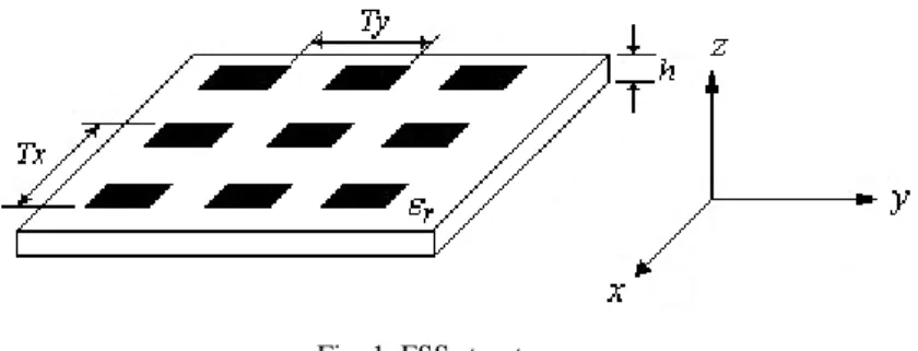
of the electromagnetic spectrum such as microwave and millimeter wave [5]. Figure 1 illustrates some
FSS composed of conducting patch elements spaced with periodicities Tx and Ty in x and y directions, respectively. These patches are printed on a dielectric layer with permittivity r and thickness h.
Fig. 1. FSS structure.
Several researchers have focused studies on FSS with multiband response recently. This is because
Multiband Frequency Selective Surfaces with
a Modified Multifractal Cantor Geometry
Érico Cadineli Braz
Federal Institute of Education, Science and Technology of Rio Grande do Norte (IFRN) Campus Natal – Zona Norte
Academic Department
Rua Brusque, 2926, Conjunto Santa Catarina, Potengi, Natal-RN, CEP: 59112-490 Telephone: + 55-21-84-4006-9500, e-mail: [email protected]
Antonio Luiz Pereira de Siqueira Campos Federal University of Rio Grande do Norte (UFRN)
Communication Engineering Department
Brazilian Microwave and Optoelectronics Society-SBMO received 28 Dec 2013; for review 08 Jan 2014; accepted 16 July 2014
Brazilian Society of Electromagnetism-SBMag © 2014 SBMO/SBMag ISSN 2179-1074
several applications, such as mobile communications and wireless computer networks need multiband
operation with close resonance frequencies. Fractal geometry is a very good solution for this problem.
These structures are recognized by their self-similarity properties and fractional dimension [6].
Fractal curves are based on a mathematical concept of geometry [7]. The geometrical shape of
fractal FSS has a large effective length and it can be designed in several forms. Fractal shapes have
some interesting properties such as the possibility to obtain an arbitrarily big electrical length
confined in a finite volume. This property is effective to reduce the spacing between resonant
elements in FSS. These structures cannot be used in design of multiband FSS with adjustment of the
ratio between the resonance frequencies, because it has a single fractal dimension.
The use of FSS with fractal elements enables the development of compact spatial filters with better
performances when compared with conventional structures [8]. Several fractal iterations can be used
to design FSS with multiband frequency response associated to the self-similarity contained in the
structure [9]. Various self-similar fractal geometries, such as Sierpinski, Minkowski, and Dürer’s
pentagon were previously used to design dual band FSS [10] – [12].
The aim of this paper is to design multiband FSS with close resonance frequencies. For this reason,
a multifractal Cantor curve is chosen. This geometry can be used to design multiband FSS because it
allows the construction of structures with multiple ratios between adjacent resonance frequencies, i.e.,
multiple fractal dimensions. So, we proposed the use of multifractal Cantor patch elements to design
multiband FSS that can be applied in C-band (4 – 6 GHz) and X-band (8 – 12 GHz).
II. MULTIFRACTAL CANTOR GENERATION PROCESS
The main attraction of fractal geometry derives from its ability to describe an irregular shape, as
well as other objects of complex shapes whose traditional Euclidean geometry cannot parse. This
phenomenon is often expressed in the spatial domain or the time domain based on statistical laws of
scale and is mainly characterized by a behavior based on the power law.
Moreover, another fundamental characteristic of fractal objects is that their metric properties, such
as length or area, are a function of the measuring scale. Recently, the work presented in [13] has
defined a fractal set as a set for which Hausdorff dimension is greater than its topological dimension
(integer which defines the geometry of the Euclidean object). However, studies of the FSS with fractal
elements were performed by analyzing only monofractal geometry structures, whose share of adjacent
resonance frequencies is approximately equal to fractal dimension, but with fixed ratios between
adjacent resonance frequencies, due to the single fractal dimension.
The FSS proposal is based on the multifractal Cantor geometry. A multifractal geometry is a
combination of two or more fractals each with its own fractal dimension [13]. The multifractal Cantor
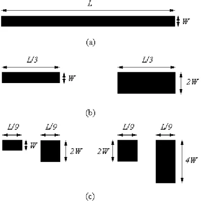
geometry is formed by an iterative process starting with initiator (K0) of length L and width W. First, the initiator is partitioned into three non overlapping segments and with the middle segments
Brazilian Microwave and Optoelectronics Society-SBMO received 28 Dec 2013; for review 08 Jan 2014; accepted 16 July 2014
Brazilian Society of Electromagnetism-SBMag © 2014 SBMO/SBMag ISSN 2179-1074
[14]. In addition, we can allocate a probability to each subinterval at each division. The generation of
a set fractal Cantor geometry is shown in Figure 2.
Fig. 2. Fractal Cantor geometry: (a) Level zero, (b) level one and (c) level two.
In this example, we allocated an existing probability of 2/3 in an interval being divided to the
right-hand subinterval, and 1/3 to the left. The existence of probabilities to non-uniform growth of a
multifractal Cantor geometry has the advantage of compressing multibands to a smaller spectral
interval.
0 n n
(1)
Thus, the segment of the left of
1 is attributed to mass p1 and p2 mass right segment. Divide the mass of each segment
1 between the two segments of
2 in proportion p1:p2. The process continues so that the mass of each segment
n is divided between the two segments of
n1 the ratio p1:p2. Therefore, the nth level is the set of
n with 2n intervals and length 3-n. Hence, μn be the probability measure of the nth fractal level.So, if I is an interval of
n we obtain:1 2 ( ) k n k n I p p
(2)Brazilian Microwave and Optoelectronics Society-SBMO received 28 Dec 2013; for review 08 Jan 2014; accepted 16 July 2014
Brazilian Society of Electromagnetism-SBMag © 2014 SBMO/SBMag ISSN 2179-1074
Now, generalizing the above definition for all the subintervals, it has been
n(y) as the setcontaining the subintervals of width n, such that I x
n(y), then define the local dimension or Hölder exponent y as:log( ( )) log( ) n n I y
(3) Also, let nN the number of subintervals of width n contained in
n(y):!
!( )!
n
n N
k n k
(4)
where, n= 1,2,... iteration is analyzed and k= 0,1,2,... represents the range analyzed.
Then, by analyzing figure 2 when n=2, it follows that the local dimension for the first interval is given by: 2 2
log(3 )
1
log(3 )
y
Similarly, one gets to the last interval:
2
2
log( )
3
0,3691
log(3 )
y
And for the penultimate interval we:
2
1 2
log(
)
3 3
0, 6846
log(3 )
y
The number of subintervals of width 3-n is N2(1)= 1, N2(0,3691)= 1 and N2(0,6846)= 2. This means that the number of boxes width 3-2 needed to cover, for example, N2(0,6846) are two.
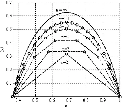
If we consider only the y values greater than zero, defined for y > 0 a function f(y) as:
log(
)
( )
log(
)
n n n Nf y
(5)The function fn(y) when n
is known as multifractal spectrum and represented by lim( ) n
f y
n . In Figure 3 is shown a spectral diagram for the multifractal Cantor
n = 2, 3, 5, 10, 20
and n
. Moreover, it appears that the multifractal spectrum has a maximum value of the fractaldimension of monofractal Cantor and the graph shows a symmetry that is characteristic of a
Brazilian Microwave and Optoelectronics Society-SBMO received 28 Dec 2013; for review 08 Jan 2014; accepted 16 July 2014
Brazilian Society of Electromagnetism-SBMag © 2014 SBMO/SBMag ISSN 2179-1074
Fig. 3. Spectral diagram for multifractal Cantor.
This process is described using an iteration function system (IFS) represented by a self-affine
transformation which is represented in a matrix form as:
0 0
0 0
i i i
i
i i i i
x a b x e
x w
y c p d y f
y
(6)
with,
1 2 n
1
p
p p0
1 2
i
p
, i
, ,...,Nwhere pi is the probability associated with the measure of multifractal curve in spatial direction. The variables x and y represent the coordinates of the transformed layer. The variables x0 and y0 represent the coordinates of the initiator. The variables ai, bi , ci , di , ei and fi are the transformation coefficients. Table I lists the IFS coefficients for the set of multifractal Cantor geometry shown in Figure 2.
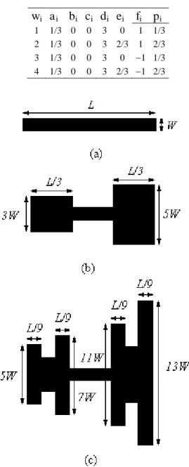
TABLE I.IFS COEFFICIENTS FOR THE SET OF MULTIFRACTAL CANTOR GEOMETRY
wi ai bi ci di ei fi pi
1 1/3 0 0 1 0 0 1/3 2 1/3 0 0 1 2/3 0 2/3
The proposed geometry is based on the multifractal Cantor geometry. Initially, the design of FSS is
Brazilian Microwave and Optoelectronics Society-SBMO received 28 Dec 2013; for review 08 Jan 2014; accepted 16 July 2014
Brazilian Society of Electromagnetism-SBMag © 2014 SBMO/SBMag ISSN 2179-1074
investigated in this article and it is shown in Figure 4. As we can see, the mid segment is not removed.
Due to this fact, we put the name as a modified multifractal Cantor geometry.
TABLE II.SET OF LINEAR TRANSFORMATIONS APPLIED TO A MULTIFRACTAL CANTOR GEOMETRY
wi ai bi ci di ei fi pi
1 1/3 0 0 3 0 1 1/3 2 1/3 0 0 3 2/3 1 2/3 3 1/3 0 0 3 0 1 1/3 4 1/3 0 0 3 2/3 1 2/3
Fig. 4. Multifractal Cantor geometry: (a) Level zero, (b) level one and (c) level two.
III. RESULTS AND DISCUSSIONS
This section presents numerical and experimental results that illustrate the analysis of the geometry
discussed above in the calculation of the scattering parameters of FSS structures. The numerical
analysis was performed with the Ansoft Designer software.
The first analysis was about the effect of the dielectric relative permittivity on the FSS response.
Figure 5 shows numerical results of the transmission coefficient of FSS using a modified multifractal
Cantor curve for a dielectric permittivity of 2.2. The initiator has dimensions W = 15 mm and L = 1.8 mm. We simulate FSS with modified multifractal Cantor geometry levels 1 and 2. As we can observe,
Brazilian Microwave and Optoelectronics Society-SBMO received 28 Dec 2013; for review 08 Jan 2014; accepted 16 July 2014
Brazilian Society of Electromagnetism-SBMag © 2014 SBMO/SBMag ISSN 2179-1074
frequency used in simulation, while the multifractal geometry level 2 presents two resonant
frequencies at 5.46 GHz and 10.64 GHz.
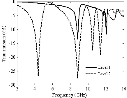
Figure 6 shows numerical results for the transmission coefficient of FSS using a modified Cantor
multifractal curve for a dielectric permittivity of 4.4. The initiator was the same used in the previous
case. As we can observe, the level 1 geometry presents two resonant frequencies at 8.83 GHz and
12.02 GHz while the level 2 geometry presents four resonant frequencies at 4.42 GHz, 8.83 GHz,
10.48 GHz, and 11.36 GHz.
Fig. 5. Frequency response for a modified multifractal Cantor curve for a dielectric permittivity of 2.2.
Fig. 6. Frequency response for a modified multifractal Cantor curve for a dielectric permittivity of 4.4.
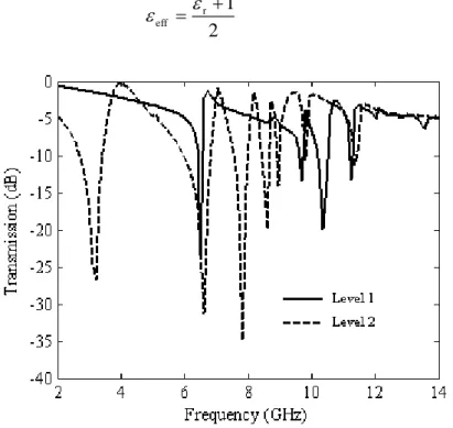
Figure 7 shows numerical results of the transmission coefficient of FSS using a multifractal Cantor
curve for a dielectric permittivity of 10.2. As we can observe, the level 1 geometry presents two
resonant frequencies at 6.51 GHz and 9.71 GHz, while the level 2 geometry presents four resonant
Brazilian Microwave and Optoelectronics Society-SBMO received 28 Dec 2013; for review 08 Jan 2014; accepted 16 July 2014
Brazilian Society of Electromagnetism-SBMag © 2014 SBMO/SBMag ISSN 2179-1074
We simulated these results for several values of dielectric permittivity and after these simulations
an expression for prediction of resonant frequencies was obtained. The expression is shown in (7):
1 1
2
n n
eff c f
D h
(7)
where c is the speed of light in vacuum, D is the fractal dimension, h is the largest height of the structure, i.e., h = 13W, for level 2 geometry, W is the width of the initiator element, n = 2k + 1 for level 1, n = k for level 2, and k = 0, 1 for Cantor level 1 and k = 0,1, 2, and 3, for Cantor level 2.
Initially, we used the electrical permittivity as:
1 2 r eff
(8)Fig. 7. Frequency response for a modified multifractal Cantor curve for a dielectric permittivity of 10.2.
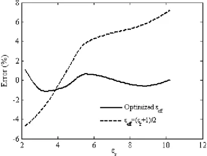
For this expression, we get an error that grows when the electrical permittivity grows and the error
was higher than 8 % for r > 10. So, as we can find in literature that the resonant frequencies are
inversely proportional to the square root of r, we performed a curve fitting based on the simulation
data, to obtain an expression for eff We performed the curve fitting using the least square method.
Figure 8 presents the average percent errors between the frequencies of resonances calculated using
(4) and simulated for the proposed structure. It is noted that for eff calculated with (5), the average
error increases and reaches close to 8% when the er grows, when using the eff obtained by the least squares method the maximum error was 1.5%. Although there is error in adjusted form, this error is
less than 2% being acceptable in many engineering applications.
In Tables III, IV and V, we listed the results of the resonance frequencies obtained with Ansoft
Designer and frequencies predicted with (4) for r = 2.2, r = 4.4 and r = 10.2, respectively.
Brazilian Microwave and Optoelectronics Society-SBMO received 28 Dec 2013; for review 08 Jan 2014; accepted 16 July 2014
Brazilian Society of Electromagnetism-SBMag © 2014 SBMO/SBMag ISSN 2179-1074
geometry on a FR4 substrate ( r = 4.4) with thickness of 1.6 mm and loss tangent delta= 0.02. Initially,
the FSS design is started with an initiator of dimensions L = 15 mm and W = 1.8 mm.
Fig. 8. Percent errors for different effective permittivities.
TABLE III. RESULTS OF THE RESONANCE FREQUENCIES OBTAINED WITH ANSOFT DESIGNER AND FREQUENCIES PREDICTED WITH (4) FORR=2.2
n Level 1 Level 2
fn (GHz) Simulated
fn (GHz) Predicted
fn (GHz) Simulated
fn (GHz) Predicted
0 10.73 10.60 5.46 5.50
1 10.64 10.60
2
3
TABLE IV. RESULTS OF THE RESONANCE FREQUENCIES OBTAINED WITH ANSOFT DESIGNER AND FREQUENCIES PREDICTED WITH (4) FORR=4.4
n Level 1 Level 2
fn (GHz) Simulated
fn (GHz) Predicted
fn (GHz) Simulated
fn (GHz) Predicted
0 8.83 8.54 4.42 4.61
1 12.02 11.49 8.83 8.54
2 10.48 10.51
3 11.36 11.49
TABLE V.RESULTS OF THE RESONANCE FREQUENCIES OBTAINED WITH ANSOFT DESIGNER AND FREQUENCIES PREDICTED WITH (4) FORR=10.2
n Level 1 Level 2
fn (GHz) Simulated
fn (GHz) Predicted
fn (GHz) Simulated
fn (GHz) Predicted
0 6.51 6.30 3.21 3.39
1 9.71 8.48 6.62 6.30
2 7.84 7.76
Brazilian Microwave and Optoelectronics Society-SBMO received 28 Dec 2013; for review 08 Jan 2014; accepted 16 July 2014
Brazilian Society of Electromagnetism-SBMag © 2014 SBMO/SBMag ISSN 2179-1074
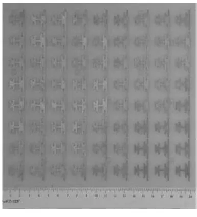
The periodicity of the array elements printed on dielectric substrate with dimensions of 200 mm x
200 mm is 24 mm and 22 mm, in x and y directions, respectively. The built prototype is shown in Figure 9 and numerical and experimental results for this FSS prototype are shown in Figure 10. A
good agreement among the results was obtained.
Fig. 9. Photograph of the built FSS.
Fig. 10. Comparison between numerical and measured results for the built FSS prototype.
Brazilian Microwave and Optoelectronics Society-SBMO received 28 Dec 2013; for review 08 Jan 2014; accepted 16 July 2014
Brazilian Society of Electromagnetism-SBMag © 2014 SBMO/SBMag ISSN 2179-1074
IV. CONCLUSIONS
In this paper, we presented a new proposal for FSS design using a modified multifractal Cantor
geometry as patch elements. The main advantage of the proposed structure is to design multiband FSS
with multiple frequency ratios between the adjacent bands and easily-built structures. In addition, the
proposed structure increases the degree of freedom in design of multiband structure according to the
number of fractal iterations and can be applied in C-band (4 – 6 GHz) and X-band (8 – 12 GHz), as
passive RFID tag applications, for example. An approximated formula was provided to resonance
frequency prediction. Although there were some differences between predicted and simulated values
this error is less than 2% being acceptable in many engineering applications. The validation of the
proposed structure was initially verified through simulations in Ansoft Designer 3.5 and then with
measurements. A good agreement between simulated and measured results was obtained. A prediction
equation for resonance frequencies was modeled and a low error between measured and predicted
frequencies was observed. The biggest differences between these results may come from the
manufacturing process. Because these errors are greater in smaller dimensions, differences appear in
the higher frequencies. A better manufacturing process is necessary, in this case.
REFERENCES
[1] Ranga, Y. et al., ‘Design and Analysis of Frequency-Selective Surfaces for Ultrawideband Applications’, Proceedings of International Conference on Computer as a Tool, Lisbon, Portugal, April 2011.
[2] Bozzi, M. et al., ‘Efficient Analysis of Quase-Optical Filters by a Hybrid MoM/BI-RME Method’, IEEE Transactions on Antennas and Propagation, 2001, 49, (7), pp. 1054 – 1064.
[3] Chen, H., Hou, X., and Deng, L., ‘Design of Frequency-Selective Surfaces Radome for a Planar Slotted Waveguide Antenna’, IEEE Antennas and Wireless Propagation Letters, 2009, 8, pp. 1231 – 1233.
[4] Huang, J., ‘The Development of Inflatable Array Antennas’, IEEE Antennas and Propagation Magazine, 2001, 43, (4), pp. 44 – 50.
[5] Munk, B. A., ‘Frequency Selective Surfaces –Theory and Design’ (John Willey and Sons, Inc., New York, 2000). [6] Falconer, K., ‘Fractal Geometry Mathematical Foundations and Applications’ (John Willey and Sons, New York,
1990).
[7] Kaur, J., Singh, S. and Kansal, A., ‘Multiband Behavior of Sierpinski Fractal Antenna’, IEEE Transactions on Power Electronics, 1994, 9, (3), pp.263 – 268.
[8] Romeu, J. and Rahmat-Samii, Y., ‘Fractal FSS: A novel dual-band frequency selective surface’, IEEE Transaction on Antennas and Propagation, 2000, 48, (7), pp. 1097 – 1105.
[9] Oliveira, E. E. C., Campos, A. L. P. S., and Silva, P. H. F., ‘Miniaturization of frequency selective surfaces using fractal Koch curves’, Microwave and Optical Technology Letters, 2009, 51, (8), pp. 1983 – 1986.
[10]Campos, A. L. P. S., Oliveira, E. E. C., and Silva, P. H. F., ‘Design of miniaturized frequency selective surfaces using Minkowski island fractal’, Journal of Microwaves, Optoelectronics and Electromagnetic Applied, 2010, 9, (1), pp. 43 – 49.
[11]Gianvittorio, J. P. et al., ‘Self-similar prefractal frequency selective surfaces for multiband and dual-polarized applications’, IEEE Transaction on Antennas and Propagation, 2003, 51, (11), pp. 3088 – 3096.
[12]Trindade, J. I. A., Silva, P. H. F., Campos, A. L. P. S., and d’Assunção, A. G., ‘Analysis of stop-band frequency selective surfaces with Dürer’s pentagon pre-fractals patch elements’, IEEE Transactions on Magnetics, 2011, 47, (5), pp. 1518 – 1521.
[13]Harte, D., ‘Multifractals: Theory and Applications’ (Chapman Hall/CRC Press, Washington, D.C., 2001).