Abstract—An accurate mathematical model of radial suspension forces for a bearingless permanent magnet slice motor (BPMSM) is of great significance to levitate the rotor stably and to improve the control accuracy of radial suspension force. In this paper, after a brief introduction on the suspension principle of the BPMSM, the accurate inductance model of two sets of stator windings (torque windings and bearing windings) is deduced. Based on the accurate inductance model and taking rotor eccentricity into account, a complete and precise mathematical model of radial suspension forces of the BPMSM is obtained. In order to confirm the validity and feasibility of this mathematical model, the experiments are carried out on a 4kW prototype of the BPMSM. The experimental results show that the control system designed by using this method has high control accuracy of radial suspension force, strong capability of resisting disturbance, and good static and dynamic performance.
Index Terms—bearingless permanent magnet slice motor (BPMSM), radial suspension force, inductance, mathematical model
I. INTRODUCTION
BPMSM (bearingless permanent magnet slice motor) is a new type of bearingless motors, whose axial length of
rotor is small compared with the diameter, in this case, the stabilization of slice rotor for the axial and two tilt
deflections (left-right tilt and forth-back tilt) can be achieved by passive suspension forces and the active stabilization
degrees are reduced to the two radial deflections only [1-2]. The BPMSM not only has all the advantages of magnetic
bearing such as mechanical contact-free, no mechanical noise, no wear, no lubrication, long operating life, high speed
and precision, but also has the superiority of small structure, high power density and high stability. The absolute
stabilization of slice rotor makes high sealing available, therefore, the BPMSM has a wide range of applications in
the fields of special electric drives such as high-speed-precision mechanical processing, aeronautics and astronautics,
life science, canned pumps, semiconductor and biotechnology industries [1]-[5].
It’s indispensable for a bearingless motor’s high-precision operation to establish an accurate model of radial
suspension forces. Over the past decades, some typical models of radial suspension forces have been put forward. In
literature [6], the model of radial suspension forces for the single-windings BPMSM is proposed on the basis of
equivalent circuit method, however, the coupling is serious because the magnetic field of torque windings and
Study on Radial Suspension Forces of Bearingless
Permanent Magnet Slice Motor Based on Accurate
Inductance Model
Huangqiu Zhu, Suming Zhu
magnetic field of bearing windings are generated by the currents of a single windings. In literature [7], segmentation
method for a consequent-pole permanent magnet bearingless motor is applied to establish the mathematical model of
radial suspension forces. But in the model, there exist air-gap width lg and thickness lm of permanent magnet that
affect the ripple of radial suspension forces, and it’s not good for the accurate and stable control of the motor. In
literature [8], a relatively accurate model of radial suspension forces, which takes eccentricity and the coupling
relationship of windings into account, is derived, but it does not consider the difference between the inductance
model in the 2-phase stator coordinate system and that in the 2-phase rotor synchronous coordinate system, therefore,
the mathematical model of radial suspension forces is still not accurate enough.
In this paper, after a brief introduction on the suspension principle of the BPMSM, the accurate inductance model
of the two sets of stator windings are deduced. Then based on the accurate inductance model and taking rotor
eccentricity into account, a complete and precise mathematical model of radial suspension forces of the BPMSM is
established. Eventually, the corresponding control system is designed and the experiments are carried out on a 4kW
prototype of the BPMSM. The experimental results show that the control system based on the proposed model of
radial suspension forces has high control accuracy of radial suspension force, fine anti-disturbance, and good static
and dynamic performance.
II. SUSPENSION PRINCIPLE OF BPMSM
According to the similarity between motor and magnetic bearings, a bearingless motor can be got when the bearing
windings are added in the stator of motor itself. In this paper, the torque windings and bearing windings of the
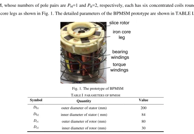
BPMSM, whose numbers of pole pairs are PM=1 and PB=2, respectively, each has six concentrated coils rounded on
six iron core legs as shown in Fig. 1. The detailed parameters of the BPMSM prototype are shown in TABLE I.
slice rotor iron core
leg
bearing windings torque windings
Fig. 1. The prototype of BPMSM
TABLE I PARAMETERS OF BPMSM
Symbol Quantity Value
DS1 outer diameter of stator (mm) 200
DS2 inner diameter of stator ( mm) 84
Dr1 outer diameter of rotor (mm) 80
DB1 outer diameter of bottom iron core yoke (mm) 164
DB2 inner diameter of bottom iron core yoke ( mm) 114
Lg length of air-gap (mm) 2
l axial length of rotor (mm) 20
P rated power (kW) 4
material of stator Steel_10
material of permanent magnet rotor NFeB35
magnetization of permanent magnet rotor parallel magnetization
m quality of slice rotor (kg) 1
PM pole pairs of torque windings 1
PB pole pairs of bearing windings 2
PPM pole pairs of slice rotor 1
W1 turns of torque windings 100
W2 turns of bearing windings 100
J rotary inertial of rotor (kg·m2
) 0.000 59
The currents in torque windings and bearing windings generate magnetic fields of torque windings and bearing
windings, respectively. As a function of the two magnetic fields with different numbers of pole pairs, the original
balanced air-gap magnetic field is broken and in this case a radial suspension force can be generated to realize the
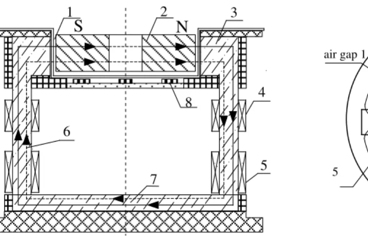
stabilization of rotor. Fig. 2 shows the magnetic circuits and active suspension force generation principle of the
BPMSM. The axial and radial sectional views of magnetic circuits are shown in Fig. 2(a) and Fig. (b), respectively. As
shown in Fig. 2(a), the magnetic force lines of torque windings pass through two spatial opposite iron core legs, bottom
magnetic yoke, air gap and permanent magnet slice rotor (The magnetic force lines of bearing windings are similar and
they pass through two adjacent iron core legs, bottom magnetic yoke, air gap and permanent magnet slice rotor. In Fig.
2(a), the magnetic force lines of bearing windings are not shown). The bottom magnetic yoke is ring-shaped and its ring
width is equal to the radial width of the bottom part of six iron core legs. Its inner and outer diameter are 114 mm and
164 mm, respectively.
In fact, when two windings are wound around columns parallel to the z direction (Fig. 2(a)) or wound around
columns parallel to x-y plane (Fig. 2(b)), the generated magnetic fields are same. On basis of that, when the phases of
magnetic fields of torque windings and bearing windings are both 0°, that is, the A-phase currents of torque and bearing windings both reach the maximum value, the equivalent paths of magnetic force lines in radial direction can be
regarded as the ones in Fig. 2(b). In Fig. 2(b), the air-gap flux density in air gap 1 is weakened and by contrast, that in
air gap 2 is strengthened, thus the motor generates the suspension force component Fx in x-direction. By changing the
phases of two magnetic fields, active suspension force in any direction can be achieved. In Fig. 2(b), B- and C-phase of
torque and bearing windings are not shown, x-y coordinate system is the 2-phase stator coordinates and x-axis coincides
2
4 8
5 7
N S
1 3
6
4
5
6 air gap 1
9
3
x y
Fx
air gap 2
(a) the axial sectional view of magnetic circuits. (b) radial sectional view of magnetic circuits. Fig. 2. Active suspension force generation of BPMSM.
1- air gap; 2- permanent magnetic slice rotor; 3- iron core leg; 4-bearing windings; 5- motor windings; 6- the flux linkage of motor windings; 7-bottom iron core yoke;
8- hall sensor; 9- the flux linkage of bearing windings
BPMSM needs to stabilize 5 degrees of freedom, besides two radial degrees of freedom, the axial and two tilt
deflections also need to control. The passive suspension principle of the BPMSM is shown in Fig. 3. Fig. 3(a) shows an
axial displacement of slice rotor, and two tilt deflections are shown in Fig. 3(b) and Fig. 3(c), respectively. The
relationship between three passive degrees of freedom and three-dimensional cartesion coordinates is shown in Fig. 3(d).
The origin O(0,0,0) is oriented in the space center of slice rotor. As the axial length of slice rotor is small compared with
the diameter, these three degrees of freedom can be stabilized passively according to the property of magnetic resistance
force [1]. That is, when the rotor has axial or two tilt deflections, it can return to the balanced position under the reverse
effect of magnetic resistance forces. In Fig. 3, Fp represents the magnetic resistance forces acting on the rotor, Fp1 and
Fp2 stand for the magnetic resistance force components in radial direction and axial direction, respectively.
Fp1 Fp1
slice rotor
stator stator
(a) axial displacement
Fp1
slice rotor
stator stator
Fp1
(b) left-right tilt
Fp1
slice rotor
stator stator
Fp1
(c) forth-back tilt Fp2
Fp
Fp2 Fp
Fp2 Fp
Fp2 Fp
Fp2
Fp Fp2 Fp
x(forth direction) z(axial direction)
y(right direction)
O(0,0,0)
(d) the relationship between three passive degrees of freedom and three-dimensional cartesion coordinates
III. THE MATRIX MODEL OF BPMSM
A. Inductance model of BPMSM in the 2-phase stator coordinate system
According to the theories of motor control and coordinate transformation, both phase torque windings and
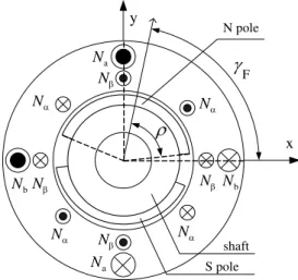
3-phase bearing windings can be transformed to 2-3-phase windings. The distribution of the two 2-3-phase windings of the
BPMSM is shown in Fig. 4, in which γF represents the mechanical angular position of slice rotor, 2ρ is the pole
arc-width of permanent magnet, Na, Nb and Nα, Nβ stand for torque windings and bearing windings, respectively.
Assuming the effective air-gap range of permanent magnet surfaced on the rotor is Ω, then it can be expressed as
(F , F ),( F ,F )
(1)
F
x
y
N N
N N
N
N
N N
a
N
a
N
b
N
b
N
N pole
S pole shaft
Fig. 4.The distribution of the two 2-phase windings of the BPMSM
In Fig. 5, O(0,0) is the center coordinates of slice rotor without eccentricity and O'(x,y) is the one with eccentricity.
θis the spatial mechanical angle, x and y represent the eccentric components in the 2-phase stator coordinate system. Supposing that the unilateral average air-gap length between slice rotor and stator is δ0, the unilateral air-gap length
is δ(θ), and the change of unilateral air-gap length caused by eccentricity is ∆δ, then the unilateral air-gap length δ(θ)
can be written as
0 0
( ) ( cosx ysin )
(2)
θ
O(0,0) x
y
O(0,0)
O'(x,y)
θ
xcosθ ysinθ
x y
y
x
stator slice rotor
O'(x,y)
0
Fig. 5.The rotor eccentricity definition
The reciprocal of equation (2) can be written as
0
2 2 2 2 2
0
1 cos sin
( ) cos sin sin 2
x y
x y xy
In the running of the BPMSM, the eccentric components (x and y) are relatively small compared to the unilateral
average air-gap length δ0, omitting the squared terms and product terms, then equation (3) can be written as
0 2 0
1 1
( cos sin )
( ) x y
(4)
The air-gap permeance per unit area along dimensional angle on the rotor surface can be expressed as
0 0
0 2 0
( ) ( cos sin )
( )
ds lr
d x y d
(5)
where l is the axial length of slice rotor, r is the radius of slice rotor and μ0 is permeability of vacuum.
In the model of the BPMSM shown in Fig. 4, the a-phase of torque windings and α-phase of bearing windings
coincide with the x-axis of 2-phase stator coordinate system. As the concentrated distribution of the two sets of
windings, the distribution of windings along the circumferential air-gap is the periodic and rectangular wave form.
Applying the Fourier series expansion to the windings and taking the fundamental windings into consideration only,
the exact distribution formulations of the two sets of windings along the circumferential air-gap can be got as [9]
2
2
4
4 a
b
cos
sin cos 2
sin 2
A Kw
A Kw
A Kw
A Kw
(6)
where K is the amplitude of fundamental windings and K =4/π, w2 and w4 are the effective turns per phase of torque
windings and bearing windings, respectively.
In the operation of the motor, magnetic energy storage is reflected as the energy storage of inductance, therefore, in
the calculation of the inductive parameters, the flux change caused by rotor eccentricity must be considered.
Supposing that the current in the a-phase of torque windings is ia, if the flux drop in the iron core magnetic circuit is
ignored, according to magnetic ohm’s law, the air-gap flux per unit area along mechanical angle in the
circumferential air-gap can be expressed as
a a
a
( )
( ) ( )
2
A i
d F d
(7)
where Fa is a-phase magnetomotive force of rotor. According to the Gauss’s law, the integration of the air-gap flux
along the circumferential air-gap is zero, in this case, substituting equation (5) and equation (6) into equation (7), the
a-phase magnetomotive force of rotor can be got as
2 a a
0 4
Kw i
F x
(8)
Similarly, b-, α- and β-phase magnetomotive force of rotor can be got as, respectively
2 b b
0 4
0, 0
Kw i
F y
F F
Substituting equation (8) and equation (9) into equation (7), the distribution formulations of flux per unit
dimensional mechanical angle on the rotor surface in the range of Ω can be expressed as
2 a
a 2 a
0
2 b
b 2 b
0
4
4 1
( cos ) ( )
2 4
1
( sin ) ( )
2 4
1
cos 2 ( ) 2
1
sin 2 ( ) 2
Kw i
d Kw i x d
Kw i
d Kw i y d
d Kw i d
d Kw i d
(10)
On the basis of the relationship between the motor flux and current, the inductance model of the two sets of
windings in the effective air-gap range of permanent magnet Ω can be written as
a a a b
a b
M
b a b b
a b B a a MB 1 1 ( ) ( ) ( ) ( ) 2 2 1 1 ( ) ( ) ( ) ( ) 2 2 1 1 ( ) ( ) ( ) ( ) 2 2 1 1 ( ) ( ) ( ) ( ) 2 2 1 1 ( ) ( ) ( ) ( 2 2
A d A d
i i
A d A d
i i
A d A d
i i
A d A d
i i
A d A d
i i
L L L b b ) 1 1 ( ) ( ) ( ) ( )2i A d 2i A d
(11)where LM and LB are the self-inductances of torque windings and bearing windings, respectively. LMB is the mutual inductance of the two sets of windings, ib, iα and iβ are the currents in b-phase, α-phase and β-phase, respectively.
Substituting equation (6) and equation (10) into equation (11), the inductance model of the two sets of windings can
be finally written as
2 2 2 0 0 2 2 2 2 0 0
4 0 F 4 F
B
4 F 4 0 F
MB 0 1
F F 2 F F 1 2 2 1 2 2
cos 4 sin 4
sin 4 cos 4
cos 2 sin 2 cos 2 sin 2
x xy
L
xy y
L L M
M L L
A B x y
M M
C D y x
0 0
0 0
0 0
0
F F
F F F
F
2 2 2 2
2 4
2 4
0 0
2 2 2 2
4 4
0 4
0 0
2 2
2 4 2 4
0 2 1 2
0 0
2 2 4 2
cos 4 sin 4
4 2
sin 4 , cos 4 sin 4
4 4 4
cos 4 sin 4
4 4
,
sin 4 , sin 4
4 4
sin 4 ,
4 4
4
F
x y
A
x y x
B C
x y
D
K lrw K lrw
L L
K lrw K lrw
L M
K lrw w K lrw w
M M
K lrw w M 2 0
sin 2 (13)
B. Inductance model of BPMSM in the 2-phase rotor synchronous coordinate system
For a simple deduction of radial suspension force model, transforming the above expression of the inductance
matrixes into the one in the 2-phase rotor synchronous coordinate system by applying the theory of coordinate
transformation. The inductance matrixes in the 2-phase rotor synchronous coordinates can be calculated with
T
Mr 2 M 2
T
Br 4 B 4
T
MBr 2 MB 4
L C L C
L C L C
L C L C
(14)
where LMr, LBr and LMBr are the self-inductances and mutual inductance of the two sets of windings in the 2-phase rotor synchronous coordinate system, respectively.
The transforming matrixes C2 and C4 can be written as
F F 2 F F F F 4 F F cos sin sin cos
cos 2 sin 2
sin 2 cos 2
C C (15)
According to the parameters of the prototype in TABLE I, the pole arc-width of permanent magnet 2ρ is π. In this
case, substituting equation (12) and equation (15) into equation (14), the inductance model in the 2-phase rotor
Mr 2 0 4 4 Br 0 4 4 MBr 1 1 0 0 1 0 2 0 2 L L M L L M L d q M q d L L L (16)
where d and q are the eccentric displacement components in the 2-phase rotor synchronous coordinate system. The
relationship between d,q and x, y can be written as follows.
F F F F cos sin sin cos x y d
q x y
(17)
IV. SUSPENSION FORCE MODEL AND CONTROL SYSTEM DESIGN
The radial suspension forces acting on the rotor in the bearingless motor consist of three parts: 1) the Maxwell
forces acting on the rotor in air-gap magnetic field. 2) the reaction forces of the Lorenz forces acting on the
current-carrying torque windings and bearing windings. 3) the radial forces generated by the unbalanced air-gap magnetic
field because of rotor eccentricity [10].
According to the principle of virtual displacement, the first and second parts of radial suspension forces can be
obtained by the partial derivative of the magnetic field storage on the radial displacements. Therefore, they can be
written as [11]
T
md m m
mq
F W W
F d q
(18)
Since the magnetic energy storage of the motor is reflected as the energy storage of winding inductances excited
by the currents, if ignoring the motor magnetic saturation and the magnetomotive force drop in iron core, then the
air-gap magnetic storage of the BPMSM can be expressed as
Mr MBr
T
m T
MBr Br
F 2d 2q 4d 4q
1 2
L L
W i i
L L
i I i i i i
(19)
where IF is the equivalent excitation current of permanent magnet, i2d, i2q and i4d, i4q are the current components of
torque windings and bearing windings in the 2-phase rotor synchronous coordinate system, respectively.
Substituting equation (16) and equation (19) into equation (18), these two parts of radial suspension forces can be
got as
F 2d 2q
md 4d
1
mq 2q F 2d 4q
I i i
F i
M
F i I i i
The third part of radial suspension forces increase with the rotor eccentric displacement and they remain the
proportional relationship. As the sinusoidal and symmetry of the air-gap magnetic field, this proportional relationship
is equivalent in the d-direction and q-direction (d-q coordinate system is 2-phase rotor synchronous coordinate
system), therefore, this part of radial suspension forces can be expressed as [12]
sd 2 2
s F 2d 2q
sq
( ) ( )
F d
k I i i
F q
(21)
where 2 0 2 s 2 0 9 4 lrw k .
According to equation (20) to equation (21), the complete and precise formulation of radial suspension forces can
be expressed as
d md sd
q mq sq
F 2d 2q 4d
1
4q
2q F 2d
2 2
s[( F 2d) (2q) ]
F F F
F F F
I i i i
M
i
i I i
d
k I i i
q (22)
Then in the 2-phase rotor synchronous coordinate system the current commands of bearing windings can be got as
* *
F 2d 2q
4d d
2 2
* *
2q F 2d
1 2d f 2q
4q q
F 2d 2q
s
2q F 2d
1
1
[( ) ]
I i i
i F
i I i
M i i i
i F
I i i d
k
i I i q
M (23)
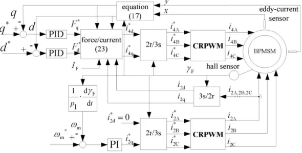
Based on the above force/current transformation (equation (23)), the control system for the BPMSM can be
designed and the corresponding block diagram is shown in Fig. 6. The torque control is realized by the method of
rotor field oriented. The displacements x and y in the 2-phase stator coordinate system are detected by eddy-current
sensors. Then by use of equation (17), the eccentric displacements d and q in the 2-phase rotor synchronous
coordinate system can be obtained. d and q are compared with the given displacements d* and q* (d*=q*=0), then the differences are regulated by two Proportional-Integral-Derivative (PID) controllers to acquire radial suspension force
commands *
d
F and *
q
F in the 2-phase rotor synchronous coordinate system. On the base of force/current
transformation (equation (23)), the current commands of bearing windings * 4d
i and * 4q
i can be acquired and are further
transformed into three phase current commands * 4A
i , * 4B
i and * 4C
i . Lastly the three phase current commands are modulated by current regulation pulse width modulation (CRPWM) and three practical currents are generated to
Fig. 6. Control system block diagram
V. ANALYSIS OF EXPERIMENTAL RESULTS
An experimental platform is constructed on the basis of the above control system block diagram. TMS320F2812
DSP is used as the digital controller of the experimental platform.
Fig. 7 shows the experiment results. Fig. 7(a) is the waveforms of radial displacements in the x- and y-direction
when the motor runs at 1 000 r/min. Fig. 7(b) shows the waveform of radial displacement in the x-direction when the
rotor speed is changed from 1 000 r/min to 2 000 r/min (the displacement in the y-direction is similar with the one in
the x-direction). As can be seen in Fig. 7(b), the vibration amplitude in the x-direction is less than 150 μm, which is
very small compared to the unilateral average air-gap length (2 mm), this indicates that the slice rotor is still in a
stable suspension state. When the speed remains at 1 000 r/min, a disturbance force in radial direction is acted on the
rotor, Fig. 7(c) shows the waveforms of the displacements in the x- and y-direction. As shown in Fig. 7(c), the slice
rotor can be suspended stably again after a short time of unstable suspension. In Fig. 7(d), the accuracy of radial
suspension force based on the inductance model is verified by the test values and the finite element analysis (the
parameters of the finite element model are based on the BPMSM prototype), and it can be seen that the errors among
the three are very small and the control system has high control accuracy of radial suspension force. In the test, the
rotor speed can be regulated from 0 r/min to 2 000 r/min continuously with the steady error less than 2 r/min, the
system has good speed regulation performance.
From above analysis, the control system for the BPMSM based on the proposed mathematical model of radial
suspension forces has high control accuracy of radial suspension force and strong capability of resisting disturbance,
(a) The displacements when the motor runs at 1000 r/min (b) The displacement in the α-axis during the speed increase
(c) The displacements under a disturbance force (d) The verification for the control accuracy of radial suspension force
Fig. 7. Experiment results
VI. CONCLUSIONS
In 2-phase stator coordinate system, the inductance model of the two sets of windings in the BPMSM is relatively
complex. Transformed to that in the 2-phase rotor synchronous coordinate system, the model can be simplified
greatly, in which the self-inductances of two sets of windings are both consents and the mutual inductance is only
related to the displacements in the 2-phase rotor synchronous coordinate system. The control system for the BPMSM
based on the proposed mathematical model of radial suspension forces has high control accuracy of radial suspension
force, strong capability of resisting disturbance, and good static and dynamic performance.
ACKNOWLEDGMENT
This work is sponsored by National Natural Science Foundation of China (60974053), Jiangsu Province University
Achievements in Scientific Research Industrial Production Advancement Project (JHB2012-39), and the Priority
Academic Program Development of Jiangsu Higher Education Institutions ([2011]6).
REFERENCES
[1] H. Mitterhofer, W. Amrhein, “Design aspects and test results of a high speed bearingless drive,” in Int. Conf. Power Electronics and Drive
[2] M.T. Bartholet, T. Nussbaumer, S. Silber, J.W. Kolar, “Comparative Evaluation of Polyphase Bearingless Slice Motors for
Fluid-Handling Applications,”IEEE Trans. Ind. Appl., vol. 45, no. 5, pp. 1821-1830, Sept./oct. 2009.
[3] X. Sun, L. Chen, and Z. Yang, “Overview of bearingless permanent-magnet synchronous motor,” IEEE Trans. Ind. Electron., vol. 60, no.
12, pp. 5528-5538, Dec. 2013.
[4] Q. Li, P. Boesch, M. Haefliger, J. W. Kolar, et al, “Basic characteristics of a 4 kW permanent-magnet type bearingless slice motor for
centrifugal pump system,” in Int.Electrical Machines and Systems, 2008, pp. 3037-3042.
[5] J. Asama, D. Kanehara, T. Oiwa, et al, “Development of a compact centrifugal pump with a two-axis actively positioned consequent-pole
bearingless motor,”IEEE Trans. Ind. Appl., vol. 50, no. 1, pp. 288-295, Jan/Feb. 2014.
[6] J. Zhu, Z. Deng, X. Wang, “Principle and implementation of the single winding bearingless permanent magnetic slice motor,” Proc.
CSEE., vol. 28, no. 33, pp. 68-74, Nov. 2008.
[7] Q. Liao, X. Wang, Z. Deng, “Theory and Realization of 3 Pole Pairs Consequent-pole Bearingless Slice Motor,” Proc. CSEE., vol. 28, no.
36, pp. 68-72, Dec. 2008.
[8] X. Sun, L. Chen, and Z. Yang, et al, “Modeling of a bearingless permanent magnet synchronous motor considering rotor eccentricity and
coupling relationship of windings,”Transactions of China Electrotechnical Society, vol. 28, no. 3, pp. 63-70, Mar 2013,
[9] T. Tera, Y. Yamauchi, A. Chiba, “Performances of bearingless and sensorless induction motor drive based on mutual inductances and
rotor displacements estimation,” IEEE Trans. Ind. Electron., vol. 53, no. 1, pp. 187-194, Feb. 2006.
[10]M. Ooshima, T. Kurokawa, M. Sakagami, et al, “An identification method of suspension force and magnetic unbalance pull force
parameters in buried-type IPM bearingless motors,”IEEE Power Engineering Society General Meeting, 2004, pp. 1276-1279.
[11]Z. Li, Y. Luo, “New method of magnetic force density computation for turbo-generator based on finite element method and virtual work
principle,” Proc. CSEE., vol. 29, no. 3, pp. 71-77, Jan. 2009.
[12]W. Zuo, Y. Lv, X. Fu, et al, “Accurate mathematical modeling of radial suspension force on bearingless permanent magnet slice motors,”
Proc. CSEE, vol. 32, no. 3, pp. 103-110, Jan. 2012.
Huangqiu Zhu received the B. S. degree in Department of Automation from School of Electrical and Information Engineering, Jiangsu University, Zhenjiang, in 1987, received the M. S. degree in Management from Jiangsu University, Zhenjiang, in 1993, and received Ph. D.
degree from Nanjing University of Aeronautics and Astronautics, Nanjing, in 2000.
He was a visiting scholar in Swiss Federal Institute of Technology (ETH), Zurich, Switzerland, from November 2002 to November 2003. He is
currently a Professor in the Department of Electrical Engineering, Jiangsu University, Zhenjiang. His research interests include magnetic
bearings, magnetic suspension (bearingless) motors, motors and movement control, etc.
Since 2008, she has been with School of Electrical and Information Engineering, Jiangsu University, Zhenjiang, where he is currently an