Brazilian Journal of Physics, vol. 35, no. 3B, September, 2005 775
Thermal Neutron Computed Tomography at the Argonauta Reactor
Maria Ines Silvani, Gevaldo L. de Almeida, Rosanne C. A. A. Furieri, Instituto de Engenharia Nuclear - CNEN - C.P. 68550,
Ilha do Fund˜ao, 21945-970 Rio de Janeiro, RJ, Brazil
Ricardo Tadeu Lopes, and Marcelo J. Gonc¸alves
Universidade Federal do RIo de Janeiro - COPPE - Bloco 6. 21945-970, Rio de Janeiro, RJ, Brazil
Received on 6 July, 2005
Since 1985 the Argonauta Reactor at theInstituto de Engenharia Nuclear - IEN/CNENhas been used as a source of thermal neutrons to acquire transmission-generated radiographic images. From that time until the end of the last century, some Universities and Research Institutions have as well used the irradiation facilities of this reactor for that purpose and for technical and scientific training of personnel. Quite recently, a joint work program with theLaborat´orio de Instrumentac¸˜ao Nuclear - LIN/COPPE-UFRJhas been initiated addressing the research in the field of radiographic images using thermal neutrons, with special emphasis on Computer Aided Tomography. Within this frame, different tomographic systems each one with their intrinsic features -have been developed aiming at their use in the industry field which requires the inspection of objects exhibiting different sizes and compositions. This work focuses the developed tomographs presenting their constraints and performances such as Spatial Resolution, Modulation Transfer Function and Density Resolution. The acquired images of some objects and test-bodies are as well presented for the sake of qualitative evaluation. They show a fair agreement with the performance of the tomographic system as expected from the measured quantitative parameters.
I. INTRODUCTION
A tomographic system is constituted by a source, radia-tion detectors, ancillary electronics and mechanical devices to move the object under inspection or the source-detector set. Besides these pieces of equipment, special softwares are re-quired to control the movements and to acquire the data and reconstruct the images. Several types of systems have been developed along the last 30 years aiming mainly at a reduc-tion of the scan time, specially for medical applicareduc-tions where the image artifacts caused by certain unavoidable movements such as the patient respiration can be then minimized. The tomographs can be classified according to the their design. The systems of 1stgeneration employ a narrow radiation beam emitted by a source which moves together with the detector. This set executes a rotation-translation movement, scanning thus the object under inspection. A complete beam translation along the object length furnishes data to obtain a projection of the slice being analyzed. Additional successive projections are gathered by rotating the set source-detector at a certain an-gle and translating it again, making thus the beam to scan the object under another angle. In the 2ndgeneration systems the single detector is replaced by a set of 3 to 50 detectors redu-cing in this way the number of required translations, for a gre-ater amount of data is collected at each translation. In the 3rd generation tomographs the number of detectors is still higher, reaching 200 to 1,000 of them arranged along an arc. Under this configuration the set source-detectors performs only a ro-tation around the object. The 4th generation contains about 300 to 2,400 detectors disposed along a complete stationary ring. The collimated source emitting a fan-like beam rotates inside and along the circle of detectors. Beyond the medical area, where the object no longer has a well knownanatomy, the acquiring time and the image resolution could eventually
be non-decisive parameters. Therefore, depending on the spe-cific application, it is necessary to select the more suitable tomograph generation. Furthermore, the employed radiation should be chosen taking into account the size and composition of the object, since the interaction of the radiation with the matter depends upon its nature and energy. The thermal neu-tron (E=0.025eV), is a powerful tool for the non-destructive assay in several fields, thanks to its capability to pass through heavy materials otherwise opaque to X-rays, and due to its strong attenuation for hydrogen. These features allow the de-tection of hydrogen-bering materials such as drugs and ex-plosives encapsulated within metallic hulls. Other inspections where the neutrons have a stronger potential application than X-rays include metal corrosion, positioning of rubber gasket within metallic components and nuclear reactor fuels. Within the mentioned work program, two tomographic systems have been developed and a third one is under development, all of them using the Argonauta Reactor as source of thermal neu-trons. Their features and some acquired images of test-objects are shown in the next sections. The arrangement used at the main channel to collimate and moderate the neutrons coming from the reactor core is shown in Fig.1. The tomographs have been installed at the outlet of this channel where the thermal neutron flux is 4.46×10
5n
·cm−2·s−1.
II. 1stGENERATION TOMOGRAPHS
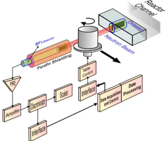
This system outlined in Fig.2 was the first one to be deve-loped and uses aBF3neutron detector [1].
776 Maria Ines Silvani et al.
FIG. 1: Collimation and moderation arrangement installed inside the main reactor channel used as source of thermal neutrons for all to-mographs.
FIG. 2: First Generation Tomographic System.
shielded with a cadmium layer and surrounded by a 20 cm-diameter cylindrical paraffin block, except at its front face. In this system, source and detector are kept static while the ob-ject is fixed at the tomographic table which executes rotation and translation movements controlled by a microcomputer. In order to achieve a narrow and parallel beam as required by this type of tomograph, small aperture slit-collimators have been utilized; one close to the source and another at the detector front face, both with the same aperture. To characterize the system and compare the acquired images with those expec-ted from the quantitative parameters, the spatial [2] and den-sity resolutions [3] have been measured by using a homogene-ous aluminum cylinder. The tomographies have been carried out with different pair of collimators, with different apertures. The performance of the system has been assessed by using the image of an aluminum cylinder. An average macroscopic cross-section of 0.096cm−1has been found which is in good agreement with the literature (Σt=0,099cm−1) [4]. The Fig.3 shows the impact of the collimator aperture on the spatial and density resolutions, while Fig.4 shows images of a test-object and a small electrical motor acquired with this system.
An aluminum cylinder provided with orifices containing rods of different materials has been used as a test-object. Af-ter a scale where the darker gray tonalities are related to the lower macroscopic cross-sections, it can be observed that the system reproduces consistently these parameters. Although tomographs belonging to this generation demand longer ac-quisition time lapses, they have the capability to handle larger
FIG. 3: Density and spatial resolution obtained under several col-limator apertures for the neutron tomographic system using a BF3
detector.
FIG. 4: (a) Test-object. Σ= macroscopic cross-section. (b) Cross-sections of an electric motor. The tri-pole rotor and the set collector-brushes are clearly visible.
objects than the detector dimensions, which is an advantage-ous option for application in the industry.
III. 3rdGENERATION TOMOGRAPHS
Brazilian Journal of Physics, vol. 35, no. 3B, September, 2005 777
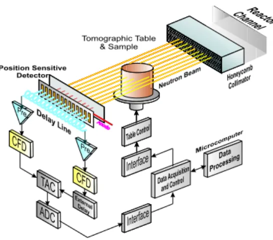
the stopping power. The filling-gas pressure was kept below 3 atm. In the second approach the gas pressure has been in-creased to 10 atm. To withstand this higher value, the detector window has been replaced by a thicker one, an engineering constraint which degraded the detector resolution.
FIG. 5: Third Generation Tomographic System.
The spatial resolution for the system was evaluated th-rough its Modulation Transfer Function-MTF, determined using double-slit collimators with different spatial frequen-cies, i.e., having different gaps between the slits. This reso-lution reaches values around 900µm. Although systems of this kind limit the maximal size of the object under inspection to the detector window length, it requires a shorter acquiring time lapse than the 1st generation ones, since a sample trans-lation is no longer required. On the other hand, nothing can be done to improve its resolution, for it is tied to the intrinsic resolution of the detector. In the 1stgeneration systems howe-ver, the system resolution can be enhanced by narrowing the collimator apertures. Some images acquired with this system are shown in the figures 6,7, 8 and 9.
FIG. 6: Images of test-objects acquired with the third generation sys-tem. (90 projections, acq. time=90min).
Aluminum and lead are not visible in the teflon matrix for their cross-sections are very close to that of teflon. The brass is readily visible due to its copper contents. The capability of the neutron to pass through heavy metallic materials such as lead and stainless steel allows for instance the detection of explosives encapsulated in metal jackets (used in the air-space industry) and the visualization of its inner structure. This is
FIG. 7: Images of teflon and aluminum cylinders containing acrylic and metallic inserts.
FIG. 8: Image of a lead gasket containing explosive.
important for the non-destructive quality control of the final product where features such as density, voids, alien materials, etc., can be determined.
IV. 5thGENERATION TOMOGRAPHS
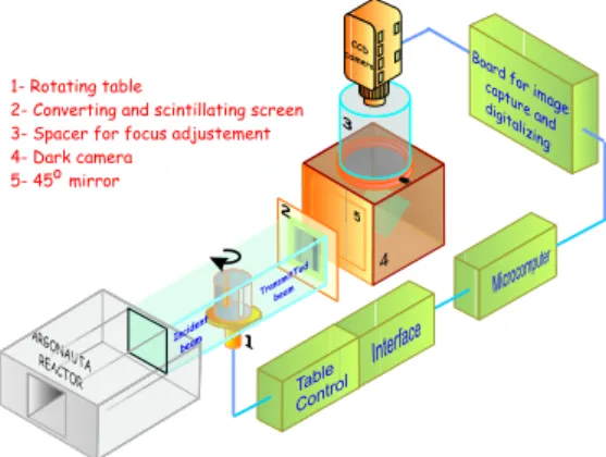
Aiming at the acquisition of 3-D tomographic images in real-time or close to it, a system using a CCD-camera ran-ked as a 5th generation system, is currently being developed according to the layout presented in Fig. 10.
It is constituted by a scintillation screen - containing mate-rials capable to convert neutrons into charged particles which loose their energy yielding visible light - and an optical sys-tem coupled to a CCD camera. As the neutron beam inter-cepted by the object hits that screen, a light-shadow pattern is drawn, furnishing a neutron attenuation image of the object cross-section. This image is then reflected by the mirror to the optical system placed outside the neutron beam and perpen-dicular to it, avoiding thus direct neutron radiation damages to the CCD camera. All components are enclosed within an aluminum box lined with a cadmium sheet acting as neutron shielding eliminating thus the scattered neutrons. The CCD camera is coupled to a computer by means of a proper
778 Maria Ines Silvani et al.
FIG. 10: Tomographic system using a converter-scintillating screen and a CCD-camera.
face and its analogic image is converted to a digital format
using a developed software. Currently, this system is being utilized to acquire radiographic images caught by a conventi-onal photographic camera, in order to gather experience and optimize parameters. The Figure 11 shows some qualitative results obtained with this system which is yet under develop-ment.
FIG. 11: Thermal neutron radiographic images cast on the converter-scintillating screen and caught by a conventional 50 mm / f 1.8 pho-tographic camera using an ASA 400 film and an exposition time of 30 seconds.
[1] M. I. Silvani, R. T. Lopes, and R. C. A. Furieri, Tomografia Com-putadorizada 2D com Nˆeutrons T´ermicos e Detector Puntual, V ENAN (2000).
[2] W. A. Kalender, Computer Tomography, 1 ed., MCD Velag, (2000).
[3] P. Reimers, et al, Nuclear Instruments and Methods in Physics Research,221, 201 (1984).
[4] D. J. Rugles and J. A. Harvey.Neutron Cross Sections, Brookha-ven National Laboratory, Upton, New York, (1955).
[5] M. I. Silvani, “Computed Tomography with thermal neutrons and a Position Sensitive Detector,” DSc. Thesis, COPPE/UFRJ-Brazil 2001 (In Portuguese).
[6] M. I. Silvani, et al, Nuclear Instruments and Methods in Physics Research B,13, 294 (2004).