ABSTRACT: Modern electronic support (ES) systems are descended from systems intended for the detection of small numbers of high-power radar systems, and are thus not suitable for the low-power transmitters and dense signal environments typical of commercial communication networks. A new ES-system architecture is proposed to allow the detection of large numbers of low-power emitters and the estimation of their angle of arrival. The proposed architecture has a number of beneits including versatility, suitability for deployment on airborne platforms, and modularity.
KEYWORDS: Radio receivers, Electronic warfare, Surveillance, Radio communication, Wireless communication.
Architecture for ES Receiver Systems
Targeted at Commercial Wireless
Communications
Warren Paul du Plessis1INTRODUCTION
Commercial wireless communication systems, especially cellular networks, are increasingly being used by criminal, paramilitary and military operators. Examples of such use include rhino poaching (Beaudufe, 2012), guiding illegal immigrants (Lacey, 2011), and insurgent attacks (Strother, 2007). he use of commercial cellular phones to co-ordinate complex operations is motivated by the low cost and wide availability of reliable cellular communications. Even the United States’ military is evaluating the use of smartphones by its soldiers (Milian, 2012). he location and tracking of cellular systems is thus becoming increasingly important, as shown by the passage of legislation such as the Regulation of Interception of Communications and Provision of Communication-related Information Act (RICA) in South Africa (RSA, 2002).
While the natural approach to achieve the detection and tracking of cellular phones would appear to be the use of the cellular network itself, this is generally not feasible. Firstly, a legal framework must exist to ensure that cellular network operators are required to provide the necessary information to security forces. However, privacy concerns in modern democracies mean that such a framework is diicult and time-consuming to establish — if it is possible at all. But even then, such a framework would only apply to network operators in one country, and many of the activities described above are perpetrated across the borders between nations. Nations are justiiably hesitant to grant other nations even limited access to information about and control over their industries (cellular network operators, in this case) and citizens, especially before criminal activities have been proved. It is thus unlikely that the required level of access to cellular
1.University of Pretoria – Pretoria/Gauteng – South Africa
Author for correspondence: Warren Paul du Plessis | Department of Electrical, Electronic and Computer Engineering, University of Pretoria | Pretoria/Gauteng – South Africa | E-mail: [email protected]
networks will be achieved within a reasonable time frame, if it can be achieved at all.
his reality leads directly to a requirement for communications intelligence (COMINT) electronic support (ES) receivers which can detect and locate cellular phones. However, this simple-sounding task is noticeably more challenging than it might appear. he success of cellular systems means that these systems have a large number of users, many of whom will be actively accessing the network at any given time. Separating individual users — let alone identifying criminal or paramilitary users — in such a dense signal environment is extremely challenging. Furthermore, cellular networks are designed to make sure that base transceiver stations (BTSs) and mobile devices transmit only the minimum power necessary to maintain a reliable connection. his means that all transmitters of interest will be operating at low power, further complicating their detection. Finally, cellular transmissions tend to be very short, and slow frequency hopping (in which BTS and mobile devices gradually change their operating frequency) is sometimes implemented to reduce the efects of fading. he probability of intercept (POI) of a receiver is thus reduced unless all frequencies of interest are monitored continuously. Furthermore, integration times are limited by the duration of the transmitted signal rather than by the receiver system requirements.
Modern ES systems are descended from systems developed to detect and locate a relatively limited number of high-power radar transmitters. As described above, commercial cellular systems comply with neither of these assumptions, suggesting that traditional ES systems will not be efective in this role. here is a requirement for ES receivers speciically developed for COMINT of cellular communication systems. his paper describes the architecture of an ES system that is targeted at the detection and location of cellular phones. his architecture is based on the use of large numbers of relatively simple receiver elements.
CHALLENGES ASSOCIATED WITH ES FOR CELLULAR COMMUNICATIONS
Challenges associated with ES for commercial cellular systems are considered below with the emphasis on the Global System for Mobile Communications (GSM) standard due to its widespread adoption.
Low Signal Power
he power transmitted by a mobile device is extremely low both as a result of device limitations and of power control. Mobile devices are small and are powered by batteries, limiting the power
available. For GSM systems operating in the E-GSM 900 and DCS 1800 bands, mobile devices are required to have a maximum transmit power of 33 dBm (2 W) and 30 dBm (1 W), respectively (3GPP, 2005). However, these speciications have a tolerance of ±2 dB under normal conditions and ±2.5 dB under extreme conditions (3GPP, 2005), so these values could be as low as 30.5 dBm (1.1 W) and 27.5 dBm (0.56 W) in the E-GSM 900 and DCS 1800 bands respectively, while still complying with relevant speciications.
However, a far greater concern for a cellular network is the interference caused by mobile devices and BTSs which transmit more power than required for reliable communications. Modern cellular systems thus implement power control whereby the power transmitted by a device can be reduced to minimise interference. he GSM standard allows power to be reduced in 15 steps of 2 dB each, therefore enabling power reduction of 30 dB (3GPP, 2005). However, these values are subject to a tolerance of ±5 dB under normal conditions and ±6 dB under extreme conditions (3GPP, 2005), so power levels in the E-GSM 900 and DCS 1800 bands can be as low as -1 dBm (0.79 mW) and -6 dBm (0.25 mW), respectively.
Dense Signal Environment
In 2011, there were an estimated 5.6 billion mobile connections worldwide (Gartner, 2011) with a global population of 7 billion people (PRB, 2011). Africa had an estimated 649 million subscribers by the end of 2011, so roughly two out of three people in the continent have some sort of mobile connectivity (BBC News, 2011). his extremely large number of users of commercial cellular systems coupled with the limited bandwidth available for such systems (Lazarus, 2010) leads to very dense signal environments.
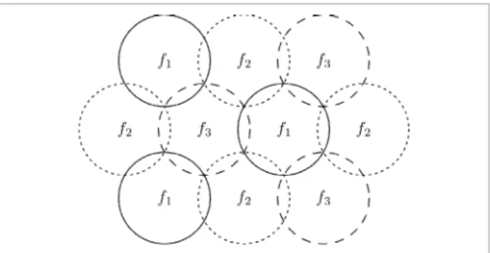
Maximal use is made of the narrow bandwidths available for commercial communication systems by using a cellular approach whereby frequencies are reused at distances which are suicient to minimise interference. Figure 1 shows how frequencies could
be reused in a highly idealised cellular structure, and while the reality will not be this neat, the same basic principles apply. Since ES systems will be expected to have ranges much greater than BTSs to minimise the number of systems required, it is clear that any ES system will detect a large number of signals which overlap in both time and frequency. To further complicate matters, newer systems like the Universal Mobile Telecommunications System (UMTS) and Long-Term Evolution (LTE), which are based on techniques such as carrier-division multiple access (CDMA) and orthogonal frequency division multiplexing (OFDM), are speciically designed to have users overlap in both time and frequency. he traditional means for deinterleaving radar signals are inadequate in such dense signal environments.
Short Signals With Changing Frequencies
Communication signals tend to be very short mainly as a result of the use of time-division multiple access (TDMA) to support multiple users or time-division duplex (TDD) to separate uplink from downlink. Furthermore, mobile devices only transmit when data are available both to reduce interference and to improve battery life.
GSM uses a combination of frequency-division multiple access (FDMA) and TDMA to support multiple users (Eberspächer et al., 1999; Redl et al., 1995). FDMA is achieved by using a 200-kHz channel spacing over the available bands. TDMA is implemented by allowing each frequency channel to support eight logical channels with timeslots lasting 577 μs, and a frame of eight timeslots lasting 4.615 ms. However, a GSM burst is shorter than a full timeslot at 547 μs to ensure some robustness to timing diferences caused by range. An ES system thus cannot use the long averaging typical of many ES systems.
GSM implements slow frequency hopping whereby the channel frequency changes from burst to burst (Eberspächer et al., 1999; Redl et al., 1995). GSM also allows discontinuous transmission to reduce interference and improve battery life (Eberspächer et al., 1999; Redl et al., 1995). his approach can be particularly efective as normal speech has pauses accounting for approximately 50% of the total conversation. Together, these two characteristics mean that the POI of a GSM signal can be extremely low.
Scenario Geometry
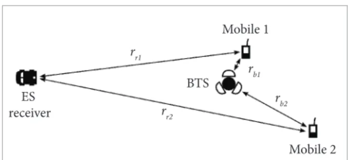
he relative positioning of a mobile phone, BTS and ES receiver has a major efect on the ES receiver requirements. Two important scenarios are shown in Fig. 2.
Mobile 1 in Fig. 2 is extremely close to the BTS (r
b1 is small) and uplink power control will ensure that this device transmits the minimum allowable power. he ES receiver is thus tasked with detecting the mobile’s extremely weak signal at long range (r
r1). his type of scenario can arise both in urban and rural environments. Cells tend to be small in urban environments to accommodate high user densities (Eberspächer, J. et al., 1999), so mobile devices will always be near a BTS. In a rural environment, a spotter on a hilltop could be underneath a BTS positioned on the same hilltop.
Mobile 2 in Fig. 2 is at the extreme edge of the BTS’s coverage area (r
b2 is at its largest value). he uplink power control problem associated with mobile 1 is thus avoided, but the range from the mobile to the receiver (r
r2) is extremely large. he ES receiver is thus required to detect the mobile at extremely long range, and importantly, the ES receiver is required to detect the mobile at a greater range than the BTS (r
r2>rb2). his scenario will arise most frequently in rural environments, where cell sizes are maximised due to low user densities (Redl et al., 1995).
A further more subtle problem related to scenario geometry occurs when two mobile devices operating at the same frequency at the same time are positioned at substantially diferent ranges to the ES receiver. In this case, the signal from the more distant mobile device tends to be masked by the signal from the nearer mobile device.
Large Unused Frequency Bands
GSM channels have a bandwidth of less than 271 kHz and have a mere 200 kHz spacing from 880 to 915 MHz and 925 to 960 MHz for the uplink and downlink of the E-GSM 900 band, respectively, and from 1710 to 1785 MHz and 1805 to 1880 MHz for the DCS 1800 band uplink and downlink, respectively (3GPP, 2005). Even the wideband code-division multiple access (W-CDMA) technology used by the universal mobile telecommunications system (UMTS) — the successor to GSM — only uses a bandwidth of 5 MHz (3GPP, 2012). However, even these igures do not show
ES receiver
Mobile 1
Mobile 2 BTS
r r1
r r2
r b2 r
b1
the whole picture because not all allocated frequencies will be used within a speciic area.
Cellular communications are thus characterised by the use of relatively small frequency bands separated by larger frequency bands, which contain no commercial cellular signals.
DEVELOPMENT OF AN ES ARCHITECTURE FOR CELLULAR COMMUNICATIONS
Starting from the challenges previously described, an ES system architecture targeted at commercial communications systems is developed.
Implications of Challenges
he irst major challenge associated with detecting commercial communication systems is the very low signal levels at a COMINT receiver. For a ixed signal level at a receiver, the detection of a signal is determined by the parameters listed below:
• he receiver noise igure (NF). his parameter is largely dependent on the NF of the irst receiver ampliier and the losses before this ampliier (Gonzalez, 1997). Reducing these values will decrease the noise loor of the receiver.
• he antenna gain. Higher antenna gain means that a greater signal is received at the antenna output for a speciic ield strength at the receiver. However, high antenna gain inherently entails a narrow beamwidth, which will reduce the POI of short-duration signals due to the need to scan the antenna beam.
• he signal-to-noise ratio (SNR) required for detection. his SNR value will vary depending on the required detection probability and the maximum allowable false-alarm rate. For example, a detection probability of 99% with a false alarm probability of 10-6 will require a higher SNR than a detection probability of 90% with a false alarm rate of 10-3. Simple detection algorithms will require higher SNR, while more advanced algorithms can achieve acceptable detection and false-alarm rates with SNR values below 0 dB (i.e., the signal is weaker than the receiver noise). However, these advanced algorithms are computationally expensive and require powerful signal-processing hardware.
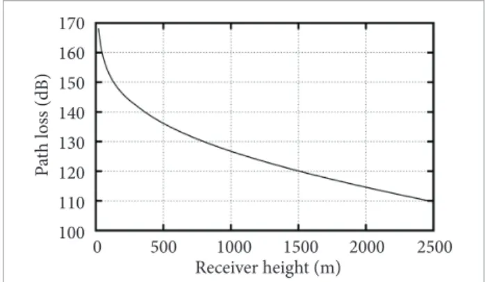
• he path loss from the transmitter to the receiver. While most of the factors that determine the path loss — such as mobile height, operating frequency and environment — are ixed, the height of the receiver can be controlled. Figure 3 shows
how the path loss reduces as the receiver height increases for a transmitter at a height of 1.5 m in an open rural area at a frequency of 900 MHz at a range of 50 km using the Hata-Davidson propagation model (TIA, 1997).
he second signiicant challenge associated with commercial communications is the large number of simultaneous signals which will be intercepted by an ES receiver. he received signals need to be separated in some way in order to allow individual signals to be detected. As mentioned before, time and frequency are insuicient to isolate received signals, so another parameter (e.g., position or angle) is required to separate commercial communication signals. Furthermore, the position of a transmitter, or at least the angle to the transmitter, is useful information in its own right. However, the number of signals that can be independently located by many algorithms — e.g., MUSIC (Schmidt, 1986) and ESPRIT (Roy and Kailath, 1989) — is limited by the number of independent receiver channels.
Related to both these challenges is the efect of stronger signals masking simultaneously-received weaker signals. he dynamic range of a receiver is one of the main factors contributing to the possibility of simultaneously detecting both strong and weak signals.
Proposed ES System Architecture
he proposed ES architecture is described next and considers the points highlighted previously. However, the proposed architecture also has a number of other advantages.
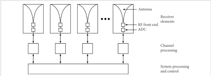
he underlying concept of the proposed system is to integrate the antenna and the complete receiver front end into single unit, and is summarised in Fig. 4. A large number of
170
160 150
140 130
120 110
100
500
0 1000 1500 2000 2500
Receiver height (m)
P
at
h los
s (dB)
such integrated receiver systems will then be combined into an ES system to achieve good system-level performance.
While this system resembles a channelized receiver (Adamy, 2001; Adamy, 2009), it difers in two important respects. Firstly, each receiver element contains a complete receiver which can be controlled independently. For example, this means that the narrowband receiver elements can be dynamically assigned to known frequencies of interest, while ignoring the bands between these frequencies — an arrangement that would be impossible with a channelized receiver in which the frequency of each channel is ixed in relation to the other channels. Secondly, the signals received by multiple receiver elements operating at the same frequency can be processed coherently in the proposed system. Coherent processing allows the achievement of antenna gain and that accurate phase-based direction inding (DF) can be performed. While the majority of spectrum-sensing algorithms are based on the use of a single sensor (e.g. Yücek et al., 2009), the coherent use of multiple sensors has been shown to be feasible (e.g. Haykin et al., 2009).
A system based on the proposed architecture in Fig. 4 will have a number of beneits, including the following.
• Large numbers of elements mean that large antenna arrays with high antenna gain can be constructed. he fact that the signal at each receiver is sampled means that multiple narrow, high-gain antenna beams can be formed simultaneously through signal processing, thereby overcoming the usual trade-of between high antenna gain and wide-area coverage.
• he narrow, high-gain antenna beams which can be formed also have the beneit of reducing the number of signals that need to be considered simultaneously by restricting the received signals to a smaller angular sector.
• he large number of elements also ofers the potential to obtain more independent samples of the environment, thereby allowing better deinterleaving of signals.
• he integration of the antenna and the radio-frequency (RF) front end will help to reduce the receiver noise igure by allowing these two elements to be designed together for optimal performance and by reducing the loss between them.
• While cost considerations will inevitably limit each receiver to the use of analogue-to-digital converters (ADCs) with lower sampling rates, it ofers the opportunity to use devices with higher dynamic range (more bits), therefore improving the system dynamic range.
• Each receiver element produces a digital output, removing the need for low-loss, phase-matched RF cables. A power-supply line, a low-frequency local oscillator signal, digital control lines and a digital output are all that each receiver element requires to function.
• he use of a large number of low data-rate streams of data is ideally suited to modern, highly parallel signal-processing technologies.
• he concept is inherently scalable depending on the number of receiver elements used to construct a system.
• he large number of elements makes the system extremely versatile as outlined below.
• he large number of elements also leads to redundancy, which will improve system reliability. Furthermore, the modular nature of the system will simplify repairs, improving the system’s availability.
his architecture is a natural match to modern digital signal processing (DSP) hardware technologies (including
Antenna
Receiver elements
Channel processing
System processing and control RF front end
ADC
ield-programmable gate arrays – FPGAs – and graphics processing units – GPUs). DSP devices are increasingly achieving high performance through the use of large numbers of relatively low-performance processors operating in parallel. Such parallel processing is ideally suited to the proposed architecture, in which large numbers of relatively low-rate data streams are generated. It might even be possible to integrate a low-cost DSP device into each receiver element to perform channel-speciic processing like calibration.
However, the greatest beneit of the natural match between the proposed architecture and modern DSP hardware is that it will be possible to better exploit the full processing power of existing DSP technologies. his creates the opportunity to allow the development and implementation of complex detection algorithms, which will lower the SNR required for a mobile device to be detected.
he fact that the system produces digital signals makes it a good match for deployment on an aerostat. Aerostats are tethered lighter-than air (LTA) systems which have a number of advantages for persistent wide-area surveillance (TCOM, 2012; Raven, 2012), and here allow the receiver height requirement previously expressed to be addressed. It will be possible to transfer the digital signals produced by the proposed system to the ground for further processing using a single digital ibre. his allows powerful DSP technologies to be used for processing while maintaining a low-weight airborne system and tether.
It is unlikely that a single aerostat system would be suicient for large-scale surveillance, so it is possible that unmanned aerial vehicles (UAVs), manned aircrat and ground-based systems will also be required. he modular nature of the architecture shown in Fig. 4 means that the same basic building blocks can be used for all these systems. For example, an aerostat would have many airborne elements with extensive ground-based signal processing, while UAV might have only a handful of elements with simpler processing, but both systems would use the same basic elements and DSP technologies. Such system
reconigurability allows the development of a family of systems which enable the unique requirements of each platform to be accommodated.
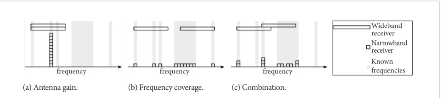
Over and above the beneits already highlighted, the versatility of the proposed architecture is one of its main attractions. A number of examples of this versatility are shown in Fig. 5 along with comparisons to a wideband ES system. For example, an ES system with an instantaneous bandwidth of 800 MHz has been developed based on the digital RF memory (DRFM) technology described by Olivier et al. (2011).
Figure 5(a) shows how high antenna gain can be achieved by allocating all receiver elements to the same frequency and performing coherent processing. he gain is determined mainly by the number of receiver elements (Lo, 1964), so a system comprising a smaller number of wideband receiver elements is unable to achieve comparable antenna gain.
Figure 5(b) shows how a wide range of frequencies can be covered by a number of independent receivers. he key point is that commercial communication systems are allocated to relatively narrow bands, which are separated by wide frequency ranges. Having the ability to monitor a large number of narrowband channels can help improve the system POI by allowing all channels in use to be simultaneously monitored. Attempting to use wideband receivers to cover commercial frequency bands is ineicient as the majority of covered frequencies have no signals of interest.
Figure 5(c) shows how a combination of these two approaches is also possible whereby high antenna gain can be achieved at certain frequencies while still allowing other frequencies to be monitored. A wideband system is simply too restricted to achieve similar performance.
Cost Estimate
hey key to the success of such a system is that the cost of each receiver element should be as low as possible to ensure
(a) Antenna gain. (b) Frequency coverage. (c) Combination.
frequency frequency frequency
Wideband receiver Narrowband receiver Known frequencies
that systems can consist of large numbers of receiver elements. Cost estimates for a single receiver element is given in Table 1, in which the low cost of each receiver element is ensured in the following ways:
• he system is limited to operation in the range of frequencies most desirable for mobile communications (below 3.5 GHz (Lazarus, 2010)). Current microwave monolithic integrated circuit (MMIC) technology means that the cost of system components in this range of frequencies is low.
• he bandwidth of each ADC is relatively low, allowing cheaper devices to be used.
• Mass production techniques including the automated assembly of receiver elements will further reduce the element cost.
It should also be noted that the cost estimate in Table 1 is conservative for the following reasons:
• It might be possible to use a cheaper substrate.
• Further cost reductions might be possible if all the RF components could be integrated into a single chip.
• It might be possible to use two mixing stages instead of three.
• he use of etched ilters rather than separate components could be viable.
• he synthesisers speciied include mixers, thereby removing the need for separate mixers.
he goal of realising low-cost receiver elements appears to be achievable. For example, Ettus Research manufactures a number of Sotware-Deined Radio (SDR) systems out of which the most expensive is the USRP N210, which sells for USD 2195 when combined with an Ettus WBX RF daughterboard and an antenna. his system comprises a 100 MS/s ADC, a 400 MS/s digital-to-analogue converter (DAC), a 50 MHz to 2.2 GHz RF front end including a receiver and a transmitter, and an FPGA capable of 32 billion multiply-accumulate (MAC) operations per second. his Ettus system is far more capable, and thus expensive, than the receiver elements proposed here, as it contains a transmitter and a receiver.
CONCLUSION
Commercial wireless communication systems are becoming increasingly important due to their adoption by criminal, paramilitary and even military users. he use of information gleaned from cellular network operators to monitor and track mobile devices faces a host of legal and political challenges which are unlikely to be overcome in the near term, if ever. here is thus a requirement for ES systems designed to perform COMINT for commercial communication systems.
Commercial wireless communications present major challenges to ES systems due to the low power transmitted and extremely dense signal environments. Furthermore, short transmission times, slow frequency hopping and discontinuous transmission can lead to an extremely low POI. Finally, isolating a single user among the millions of users of commercial communication services is a daunting task.
A new system architecture which overcomes these diiculties is proposed. his architecture is based on the use of large numbers of simple, low-cost receiver elements to achieve high system performance. his approach has the potential to achieve high antenna gain, low receiver noise igure and is well-matched to modern signal-processing technologies allowing computationally-expensive algorithms to be implemented. he fact that digital signals are generated at each receiver means that the proposed architecture is well-matched to aerostat-based deployment. he modular Table 1.Estimated cost of an individual receiver element.
Component Type Cost (USD)
Substrate Rogers RO4003C
substrate, 64 mil, 18"x24" 200
Low-noise ampliier (LNA)
Minicircuits PSA-5453+ and RFMD SGC4563Z
5
Limiter Minicircuits RLM-33+ 10
Variable attenuator Minicircuits DAT-15R5-SP+
5
Synthesiser 3x RFMD RFFC5072 30
Mixers 3x Minicircuits
LAVI-362VH+
75
Filters Minicircuits
HFTC-16+, HFCN-740D+, RHP-180+
20
ADC Analog Devices
AD9446-100
70
Additional components Capacitors, resistors, regulators, etc.
125
Etching and assembly 625
nature of the proposed system enables a family of similar systems to be developed from the same basic building blocks. Finally, this new architecture is extremely versatile, allowing combinations of high antenna gain and wide spectral coverage to be achieved as required.
ACKNOWLEDGEMENTS
he author wishes to express his sincere thanks to the anonymous reviewers for their many comments and suggestions which greatly improved this paper.
REFERENCES
3rd Generation Partnership Project (3GPP), 2005, “Technical speciication group GSM/EDGE radio access network; Radio transmission and reception (Release 1999)”, Std. 05.05, Rev. 8.20.0.
3rd Generation Partnership Project (3GPP), 2012, “Technical speciication group radio access network; User Equipment (UE) radio transmission and reception (FDD) (Release 11)”, Std. 25.101, Rev. 11.3.0.
Adamy, D.L., 2001, “EW 101: A irst course in electronic warfare”, Chapter 4, Artech House.
Adamy, D.L., 2009,” EW 103: Tactical battleield communications electronic warfare”, Chapter 4, Artech House.
BBC News, 2011, “Africa’s mobile phone industry ‘booming’” [Internet]. Available from: http://www.bbc.co.uk/news/world-africa-15659983. Accessed October 24, 2012.
Beaudufe, C., 2012, “South African success story under threat” [Internet]. Available from: http://www.sowetanlive.co.za/news/2012/05/07/ south-african-success-story-under-threat. Accessed October 24, 2012.
Eberspächer, J., Vögel, H.J. and Bettstetter, C., 1999, “GSM switching, services and protocols”, 2nd ed., John Wiley & Sons, Ltd.
Ettus, 2012, “Ettus Research” [Internet]. Available from: http://ettus. com/. Accessed October 24, 2012.
Gartner, 2011, “Gartner says worldwide mobile connections will reach 5.6 billion in 2011 as mobile data services revenue totals $314.7 billion” [Internet]. Available from: http://www.gartner.com/it/page. jsp?id=1759714. Accessed October 24, 2012.
Gonzalez, G., 1997, “Microwave transistor ampliiers”, Chapter 4, 2nd ed. Prentice Hall.
Lacey, M., 2011, “Smugglers guide illegal immigrants with cues via cellphone” [Internet]. Available from: www.nytimes.com/2011/05/09/ us/09coyotes.html. Accessed October 24, 2012.
Lazarus, M., 2010, “The great radio spectrum famine”, IEEE Spectrum, Vol. 40, No. 10, pp. 26-31.
Lo, Y.T., 1964, “A mathematical theory of antenna arrays with randomly spaced elements”, IEEE Transactions on Antennas and Propagation, Vol. 12, No. 3, pp. 257-268.
Milian, M., 2012, “U.S. government, military to get secure Android phones”, Cable News Network (CNN)” [Internet]. Available from:
http://edition.cnn.com/2012/02/03/tech/mobile/government-android-phones/index.html. Accessed October 24, 2012.
Olivier, K., Cilliers, J.E. and du Plessis, M., 2011, “Design and performance of wideband DRFM for radar test and evaluation”, Electronics Letters, Vol. 47, No. 14, pp. 824-825.
Population Reference Bureau (PRB), 2011, “2011 World Population Data Sheet” [Internet]. Available from: http://www.prb.org/Publications/ Datasheets/2011/world-population-data-sheet.aspx. Accessed October 24, 2012.
Raven Aerostar, 2012, “TIF-25K | Tethered aerostats | Raven Aerostar” [Internet]. Available from: http://ravenaerostar.com/products/ aerostats/tif-25k. Accessed October 24, 2012.
Redl, S.M., Weber, M.K. and Oliphant, M.K., 1995, “An introduction to GSM”, Artech House.
Republic of South Africa (RSA), 2002, “Regulation of Interception of Communications and Provision of Communication-Related Information Act”, Government Gazette, Vol. 451, No. 24286, pp. 2-96, Act 70 of 2002.
Roy, R. and Kailath, T., 1989, “ESPRIT – Estimation of signal parameters via rotational invariance techniques”, IEEE Transactions on Acoustics, Speech and Signal Processing, Vol. 37, No. 7, pp. 984-995.
Schmidt, R.O., 1986, “Multiple emitter location and signal parameter estimation”, IEEE Transactions on Antennas and Propagation, Vol. 34, No. 3, pp. 276-280.
Strother, T., 2007, “Cell phone use by insurgents in Iraq”, Urban Warfare Analysis Center [Internet]. Available from: http://www. babylonscover twar.com/Terrorist%20Groups/Weapon%20 Systems/Cell%20Phone%20Use%20by%20Insurgents%20in%20 Iraq.pdf. Accessed October 24, 2012.
TCOM, 2012, “TCOM aerostats – over 30 years of reliable performance” [Internet]. Available from: http://www.tcomlp.com/aerostats.html. Accessed October 24, 2012.
Telecommunications Industry Association (TIA), 1997, “A report on technology independent methodology for the modeling, simulation and empirical veriication of wireless communications system performance in noise and interference limited systems operating on frequencies between 30 and 150 MHz”, version 20.