THE COMPLEX CONTROLLER FOR THREE-PHASE INDUCTION
MOTOR DIRECT TORQUE CONTROL
Alfeu J. Sguarezi Filho
∗E. Ruppert Filho
∗∗Universidade Estadual de Campinas, FEEC-DSCE
Av. Albert Einstein, 400
Cidade Universit´aria Zeferino Vaz, Campinas, SP
ABSTRACT
This paper proposes a design and tuning method for a complex gain controller, based on the three-phase induc-tion motor mathematical model complex transfer func-tion to be used in the direct torque control at low speed which is a problem so far. The design and tuning of the complex gain is done by using the closed loop sys-tem frequency-response function. Experimental results are presented to validate the controller and operation at low speed is also explored.
KEYWORDS: Complex gain controller, Complex transfer function, Induction motor, Direct torque control.
RESUMO
Este trabalho prop˜oe um m´etodo de projeto para um controlador de ganho complexo baseado na fun¸c˜ao de transferˆencia complexa do motor de indu¸c˜ao trif´asico para uso no controle direto de torque em que a opera-¸c˜ao do motor em baixas velocidades ´e um problema. O projeto e a sintonia do ganho complexo ´e realizado com o emprego da resposta em frequˆencia do sistema em ma-lha fechada. Resultados experimentais s˜ao apresentados para a valida¸c˜ao da proposta do controlador.
PALAVRAS-CHAVE: Controlador de ganho complexo,
Artigo submetido em 22/11/2008 (Id.: 00924) Revisado em 26/02/2009
Aceito sob recomenda¸c˜ao do Editor Associado Prof. Darizon Alves de An-drade
Fun¸c˜ao de Transferˆencia Complexa, Motor de Indu¸c˜ao, Controle direto de torque.
1
INTRODUCTION
The dynamics of the three-phase induction motor is traditionally described by differential equations. The space-vector concept (Kov´acs e R´acz, 1984) is used in the mathematical representation of the motor state vari-ables such as voltage, current, and flux.
The concept of complex transfer function derives from the application of the Laplace transform to differen-tial equations where the complex coefficients are in ac-cordance with the spiral vector theory by Yamamura (1992).
Holtz (1995) proposed a three-phase induction motor mathematical model using the complex transfer function and presented the induction motor root locus. Other procedures for modeling and simulating the three-phase induction motor dynamics using the complex transfer function concept are also presented by Cad (2000).
cross-coupling in the induction machine transients and low-speed tests had not been shown.
To solve the cross-coupling between induction machine
dq transient stator currents Holtz et al. (2004) de-signed a stator-current controller using complex nota-tion. From this, the current controller structure em-ploying single-complex zeros is synthesized. Experimen-tal results demonstrate that high dynamic performance and zero cross-coupling are achieved even at very low switching frequency although the speed control had not be presented.
An alternative for induction motor drives is the direct torque control (DTC), which consists of the direct con-trol of the statorλ1 and the electromagnetic torqueTe.
DTC controllers generate a stator-voltage vector that allows quick torque response with the smallest varia-tion of the stator flux. The principles of the DTC using histereses controllers and variable switching frequency were presented by Takahashi e Noguchi (1986) and De-penbrock (1988).
Xue et al. (1990) proposed a DTC strategy using PI con-trollers and space-vector modulation to generate a sta-tor voltage based on sta-torque and stasta-tor-flux errors. This strategy has presented good torque response although low-speed tests had not been shown so far.
The literature shows the application of the control the-ory to some DTC strategies, as that one presented by Buja e Kazmierkowski (2004) and other presented by Stojic e Vukosavic (2005). Each strategy aims to the torque and to the rotor or stator flux control although the complex transfer function of induction motor is not used.
This paper proposes a design and tuning method for a complex gain controller which is designed by using the induction motor complex transfer function to control the motor. The controller is adjusted by the frequency-response function of the closed loop system. Experimen-tal results are presented for validation of the proposed controller including low speed operation.
2
THE
COMPLEX
MATHEMATICAL
MODEL
OF
THE
THREE-PHASE
INDUCTION MACHINE
The three-phase induction machine mathematical model is written with the variables referred to the dq syn-chronous reference frame and the complex state vari-ables are the stator current~i1dqand the stator flux~λ1dq.
~v1dq=R1~i1dq+λ~˙1dq+jω1~λ1dq (1)
0 =R2~i2dq+~λ˙2dq+j(ω1−P ωmec)~λ2dq (2)
The relationship between currents and fluxes are given by
"
~λ1dq
~λ2dq #
=
L1 Lm
Lm L2
~i1dq
~i2dq
(3)
The electromagnetic torque and mechanical speed are given by
Te=
3
2P Im[~i1dqconj(~λ1dq)] (4) and
Jωmec
dt =Te−TL (5)
The subscripts1, 2 and m represent the stator, rotor and magnetization parameters respectively, ω1 is the
synchronous speed,ωmec is the machine speed,R1 and
R2 are the estator and rotor windings per phase
elec-trical resistance, L1 , L2 and Lm are the proper and
mutual inductances of the stator and rotor windings,~v
is the voltage vector ,Pis the machine number of pair of poles,J is the load and rotor inertia moment andTL
is the load torque.
By combining equations (1), (2) and (3), after some al-gebraic manipulations, one can write the complex space state equations as:
˙
~λ1dq
˙
~i1dq =
a1 a2
a3 a4
~λ1dq
~i1dq +
~v1dq
~v1dq
σL1
(6)
where
a1=−jω1 (7)
a2=−R1 (8)
a3=
R
2
σL1l2
−jP ωmec
σL1
(9)
a4=−
R1
σL1
+ R2
σL2
+j(ω1−P ωmec)
Figure 1: IM block diagram.
whereσ= 1− L2m
L1L2 is the leakage coefficient.
In order to obtain the induction motor complex trans-fer function the Laplace transform is applied to (6) in accordance with the complex transfer function concept, it is assumed that the mechanical time constant of the motor is much larger than the transient electromag-netic time constants and the saturation effects is ne-glected. Thus, ωmec = constant is a valid
approxima-tion (Yamamura, 1992; Holtz et al., 2004). The induc-tion motor block diagram originated by use of (4), (5) and (6) is shown in Figure 1.
When designing the DTC control system,~v1dqis
consid-ered as the input and the~i1dq is considered as the
out-put. Therefore the induction machine complex transfer function is given by
H(s) = I1dq
V1dq
=
s+jω1
σL1
+a3
(s+jω1) (s+a4) +R1a3
(11)
whereI1dq=L n
~i1dq o
andV1dq=L {~v1dq}.
3
DIRECT TORQUE CONTROL
The direct torque control strategy allows a quick torque response and consists of the direct control of the sta-tor flux λ1 and the torque Te. The flux and torque
controllers generate a stator-voltage vector that allows quick torque response with the smallest variation of the stator flux.
This work is based in Xue’s strategy as shown in (Xue et al., 1990) which uses conventional PI controllers and space-vector modulation to generate a stator voltage based on torque and stator-flux errors.
In this present work, by using stator-field orientation, the torque and stator flux must become parts of a com-plex number, where the magnitude of the stator fluxλ1
is the real component and the torque Te is the
imagi-nary component. Hence, the reference signals and the error become a complex number and the proposed con-troller is a complex gain (a+jb). This gain has the function to generate a voltage reference vector using the stator flux-torque vector error (ελ+jεT). This way the
stator-voltage vector in this control strategy is given by
~
v1dq= (ελ+jεT) (a+jb) (12)
which means
v1d= (−εT b+ελa) (13)
v1q= (εT a+ελb) (14)
where a is the real part of the complex gain, b is the imaginary part of the complex gain, ελis the flux error
and εT is the torque error.
The block diagram of the mathematical model of the control system proposed with the complex gain con-troller is presented in Figure 2.
It can be observed in equation (12) that the complex gain changes the amplitude and phase of the vector volt-age due to the cross-coupling between the complex gain and the error vector.
The reference stator-voltage vector~v1dq is transformed
by using stator-flux positionδsto obtain the stator
Figure 2: DTC strategy with complex controller.
3.1
ESTIMATION BLOCK
The estimation of the stator flux is calculated by using the stator currents and voltages, given by
~ λ1αβ=
Z
(f emαβ)dt= Z
(~v1αβ−R1~i1αβ)dt (15)
where the subscriptαβ is used to designate the stator stationary reference frame which is being used.
The stator-flux angle is estimated by using the trigono-metric transfer function
δs=tg−
1
λ1β
λ1α
(16)
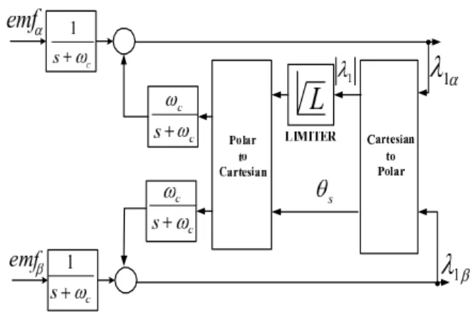
In order to achieve the stator-flux estimation for a wide speed range in drives using (15) an integration method (Xu et al., 1988; Lins, 2001) given by (17) can be used.
y = 1
s+ωc
x+ ωc
s+ωc
z (17)
where,xis the input of the integrator,z is the compen-sation signal andωc is the cut-off frequency.
Another way to obtain a better integrator performance for low speed, as shown in (17), it can be used a lim-iter (Hu e Wu, 1998). This implementation is shown in the block diagram of Figure 3.
3.2
DESIGN OF THE COMPLEX GAIN
The tuning operation of the complex gain controller re-quires the transfer function of the closed loop system, to obtain its frequency-response function.
Figure 3: Integrator block diagram.
The frequency is chosen in accordance with the the in-duction motor desired speed operation to design the complex gain.
In accordance with the DTC control strategy the induc-tion motor output has to be the stator flux magnitudeλ1
and the torqueTe. Therefore the H(s) in equation (11)
outputs have to become the stator flux magnitude λ1
and the torqueTe. The expression to obtain the stator
flux by using the stator currenti1d is given by
λ1=λ1d ∼=σ L1i1d (18)
and to obtain the electromagnetic torque through Equa-tion (4) in the dq reference frame one may use the ex-pression:
Te=
3
2P λ1i1q (19)
As the stator flux magnitude λ1 is assumed to be
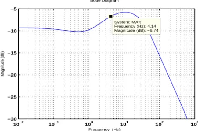
es-sentially constant through of the equations (11), (18) and (19) the new transfer function is achieved with torque and flux as output and it is given by
XλT
V1dq
=H(s)
σL1+jP
3 2λ1
(20)
where XλT = L {λ1+jTe}. The frequency-response
function of Equation (20) is presented in Figure 4.
Then, from Equations (12) and (20) one obtain the con-trol system block diagram wich is presented in Figure 5.
Bode Diagram
Frequency (Hz)
10−2 10−1 100 101 102 103 −30
−25 −20 −15 −10 −5
Magnitude (dB)
System: MAft Frequency (Hz): 4.14 Magnitude (dB): −6.74
Figure 4: Equation (20) frequency-response function.
Figure 5: System to design the complex gain
XλT
XλTref
=
(a+jb)H(s)
σL1+jP
3 2λ1
1 + (a+jb)H(s)
σL1+jP
3 2λ1
(21)
where XλTref = L
λ1ref +jTeref . At the frequency
of 4.16Hz the complex gain is chosen by using simula-tions, considering slip approximately null and the Bode criterion. The complex gain found was 125−j25. The frequency-response function of Equation (21) is shown in Figure 6 and its magnitude is near 0 dB.
Bode Diagram
Frequency (Hz)
10−1 100 101 102 103 104 −0.45
−0.4 −0.35 −0.3 −0.25 −0.2 −0.15 −0.1 −0.05
Magnitude (dB)
System: MF_gcomp Frequency (Hz): 4.17 Magnitude (dB): −0.108
Figure 6: Equation (21) frequency-response function
4
EXPERIMENTAL RESULTS
The DTC strategy was implemented using a Texas Instruments DSP TMS320F2812 platform. The sys-tem consists of a three-phase voltage source inverter with insulated-gate bipolar transistors (IGBTs) and the three-phase induction motor shown in the appendix. The stator voltage commands are modulated by us-ing symmetrical space vector PWM, with switchus-ing fre-quency equal to 2.5 kHz. The DC bus voltage of the inverter is 226 V. The stator voltages and currents are sampled in the frequency of 2.5 kHz. A conventional PI controller generates a torque reference by using the speed error. The flux and torque estimation, and the flux-torque complex regulator and speed controller have the same sampling frequency of 2.5 kHz. The encoder resolution is 1500 pulses per revolution.
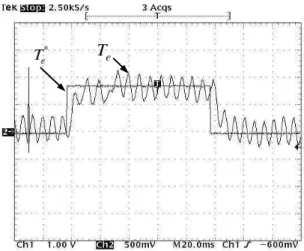
Three no-load induction motor tests were made. The first one was the response to a torque step of 12.2 Nm which is shown in Figure 7. The response of the DTC with complex controller presented a slightly better per-formance in transient and steady state when such re-sponse is compared with the rere-sponse of DTC with PI controller. It can be observed that the response time is 25 ms and the reference is followed with a small oscilla-tion. This oscillation occurs due to the natural lack of accuracy in the measurements of currents and voltages.
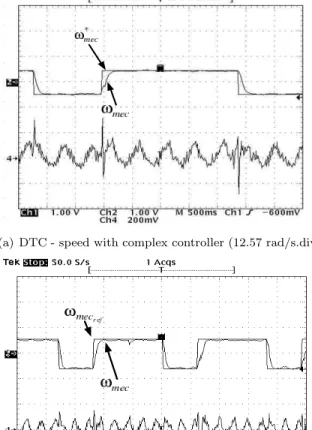
In the second test the speed varies in forward and re-versal operation and the result is presented in Figure 8. The speed changes from 13 rad/s to -13 rad/s in 1 s and the complex gain is not changed during the test. This result confirms the satisfactory performance and the ro-bustness of the controller due to the fact that the the speed reaches the reference in several conditions. The responses of the DTC with complex controller and of the DTC with PI controller have the same performance in transient and steady state. The small error occurs due the natural lack of accuracy in the measurement of the speed.
(a) DTC - Teref step input function with complex con-troller (9 Nm/div).
(b) DTC -Teref step input function with PI controller (9 Nm/div).
Figure 7: Responses to step torque operation.
5
CONCLUSION
The concept of complex vector notation associated with the complex gain controller allows the design and tuning the complex controller by using the closed loop system frequency response function.
The experimental results presented shows the satisfac-tory performance and the robustness of the controller due to the fact that the speed reaches the reference in many different conditions although the complex gain is designed for induction motor operation at 4.16 Hz. Thus, the design of complex gain has an acceptable robustness although a detailed analysis considering pa-rameters variations and other several speed operations have to be done. Due to the variable speed operation it
(a) DTC - speed with complex controller (13 rad/s.div).
(b) DTC - speed with PI controller (13 rad/s.div).
Figure 8: Speed forwad and reversal operation and cur-rent of phasea(10 A/div).
could be necessary to prepare a table with several com-plex gains designed for each speed desired or to specif-ically speed range. Thus, the complex vector notation and the complex controller can become an interesting tool for the implementation of three-phase induction motor direct control drives. Operation at low speed was explored but it requires a more complete study in the future.
ACKNOWLEDGEMENT
(a) DTC - speed with complex controller (12.57 rad/s.div)
(b) DTC - speed with PI controller (12.57 rad/s.div)
Figure 9: Speed response to step operation and current of phasea(6 A/div).
APPENDIX
Three-phase induction motor variables and parameters:
P N = 2.3kW;VN = 220 V; P oles = 4 R1 = 2.229
Ω; R2 = 1.522 Ω; Lm = 0.238485H; L1 = 0.2470H;
L2= 0.2497H;J = 0.0067Kgm 2
.
REFERENCES
Briz, F., degener, M. W. e Lorenz, R. D. (2000). Anal-ysis and design of current regulators usin complex vectors,IEEE Trans. Ind. Applicat.36: 817–825.
Buja, G. S. e Kazmierkowski, M. P. (2004). Direct torque control of pwm inverter-fed ac motors - a survey, IEEE Trans. Ind. Electronics 51(4): 744–
757.
Cad, M. M. (2000). Estrat´egias de modelagem dinˆamica
e simula¸c˜ao computacional do motor de indu¸c˜ao trif´asico, Disserta¸c˜ao de mestrado, Escola de En-genharia de S˜ao Carlos, USP - Universidade de S˜ao Paulo.
Depenbrock, M. (1988). Direct self-control(dsc) of inverter-fed induction machine, IEEE Trans.
Power Electronics3(4): 420–429.
Holtz, J. (1995). The representation of ac machine dy-namics by complex signal flow graphs,IEEE Trans.
Ind. Electron.42: 263–271.
Holtz, J., Quan, J., Pontt, J., Rodr´ıguez, J., newman, P. e Miranda, H. (2004). Design of fast and robust current regulators for high-power drives based on complex state variables, IEEE Trans. Ind.
Appli-cations40: 1388–1397.
Hu, J. e Wu, B. (1998). New integration algorithms for estimating motor flux over wide speed range,IEEE
Trans. on Power Electronics13(5): 969–977.
Kov´acs, P. K. e R´acz, E. (1984). Transient Phenomena
in Electrical Machines, Amsterdam, The
Nether-lands: Elsevier.
Lins, Z. D. (2001). Controle direto de torque para mo-tores de indu¸c˜ao - estudo e implementa¸c˜ao, Tese
doutorado, Faculdade de Engenharia El´etrica e
Computa¸c˜ao, Unicamp - Universidade Estadual de Campinas.
Stojic, D. M. e Vukosavic, S. N. (2005). A new induction motor drive based on the flux vector acceleration method,IEEE Trans. Ind. Applications20(1): 173–
180.
Takahashi, I. e Noguchi, T. (1986). A new quick-response and high-efficiency control strategy of an induction motor, IEEE Trans. Ind. Applications IA-22(5): 820–827.
Xu, X., Donker, R. D. e Novotny, D. W. (1988). A stator flux oriented induction machine drive, PESC´88
Conference Recordpp. 870–876.
Xue, Y., Xu, X., Halbetler, T. G. e Divan, D. M. (1990). A low cost stator flux oriented voltage source vari-able speed drive, Conference Record of the 1990 IEEE Industrial Aplications Society Annual Meet-ting1: 410–415.
Yamamura, S. (1992). Spiral Vector Theory of AC