http://dx.doi.org/10.1590/S1982-21702014000200021
DYNAMIC MODELING OF TUNNEL SURVEY
SPATIOTEMPORAL DATA
Modelamento dinâmico de túneis com dados espaço-temporais
i
XIAOLONG LI1 ii
JIANSI YANG2 BINGXUAN GUO1
HUA LIU2 JUN HUA3
1
State Key Laboratory of Information Engineering in Surveying, Mapping and Remote Sensing, Wuhan University, 129 Luoyu Road,
Wuhan 430079, China 2
School of Urban Design, Wuhan University, 8 South Donghu Road, Wuhan 430072, China
3
College of Mining Technology, Taiyuan University of Technology, 18 New Kuangyuan Road, Taiyuan 030024, China
xiaolong.li@whu.edu.cn; jsyang@whu.edu.cn
ABSTRACT
Currently, for tunnels, the design centerline and design cross-section with time stamps are used for dynamic three-dimensional (3D) modeling. However, this approach cannot correctly reflect some qualities of tunneling or some special cases, such as landslips. Therefore, a dynamic 3D model of a tunnel based on spatiotemporal data from survey cross-sections is proposed in this paper. This model can not only playback the excavation process but also reflect qualities of a project typically missed. In this paper, a new conceptual model for dynamic 3D modeling of tunneling survey data is introduced. Some specific solutions are proposed using key corresponding technologies for coordinate transformation of
i
Xiaolong Li, PhD candidate, Major in GIS – E-mail: xiaolong.li@whu.edu.cn ii
cross-sections from linear engineering coordinates to global projection coordinates, data structure of files and database, and dynamic 3D modeling. A 3D tunnel TIN model was proposed using the optimized minimum direction angle algorithm. The last section implements the construction of a survey data collection, acquisition, and dynamic simulation system, which verifies the feasibility and practicality of this modeling method.
Keywords: Tunnel; Survey Cross-Section; Dynamic; Three-Dimensional Modeling.
RESUMO
Normalmente, para túneis, o projeto do alinhamento e das seções transversais e a marcação do tempo são usadas para a modelagem tridimensional. No entanto, esse procedimento pode não refletir algumas qualidades do processo ou em alguns casos especiais, como deslizamento de terra. Portanto, neste artigo, propõe-se um modelo dinâmico de um túnel baseado em dados espaço-temporais a partir de levantamentos de seções transversais. Esse modelo pode não só reproduzir o processo de escavação, mas também refletir qualidades que um projeto normalmente não atende. Assim, introduz-se um novo modelo conceitual para a modelagem dinâmica 3D da topografia de túneis. São propostas algumas soluções específicas: o uso da tecnologia de chave de correspondência para transformar coordenadas de uma seção transversal de coordenadas lineares locais para coordenadas de uma projeção global; estrutura de dados de arquivos e banco de dados, e modelamento 3D dinâmico. Um modelo de túnel TIN 3D foi proposto usando o algoritmo do ângulo de mínima direção otimizado. A última seção implementa a construção da coleta e aquisição de dados de campo e de sistemas de simulação dinâmica, que verificam a viabilidade e praticidade desse método de modelamento.
Palavras-chave: Túnel; Seções Transversais; Dinâmica; Modelagem Tridimensional.
1. INTRODUCTION
Sometimes during the construction of hydropower stations or transportation systems, scores of tunnels must be excavated. Tunnel excavation positioned underground or inside mountains, is often concealed engineering. Project managers cannot see the complete picture of a project, especially in the case of long tunnels, with many branches and different shapes. Thus, it is difficult to control construction progress and quality. A dynamic 3D tunnel model supports construction progress and quality by allowing a project manager to grasp the overall project progress, and thus to optimize the allocation of resources, and to support decision-making, and command.
(ZHONG et al., 2007) can be attached to a 3D tunnel model to dynamically show the progress of a project, and even optimized ventilation time data (WANG, 2009). Although these methods represent tunneling processes intuitively, they cannot express real tunneling information. In recent years, laser scanning data are have been used to build 3D tunnel models (SEO et al., 2008; GIKAS, 2012), some management systems have been developed to manage data in the form of cross-sections. These data and models are able to accurately describe the quality of tunnel excavation, however, these systems do not manage excavation time data, so dynamic construction processes cannot be represented or visualized. Although laser scanning data can show more details about the shape of the tunnel, total station survey data is still used for most tunnel construction surveys because of the large quantity of point cloud data from laser scanning and the high costs of the technology and equipment as compared to traditional survey methods. Thus research on methods using the total station survey data (BERBERAN, 2007) and survey time to dynamically build 3D tunnel models has practical significance.
One of the motivations behind this research is to better understand dynamic processes. Not only is a 3D modeling and visualization dynamic, but so too are the data sources. In order to understand the amount and quality of construction completed in a month, tunnel construction survey teams must make a survey of a part of the new excavation at least once a month in the tunneling process. These construction survey data results are a series of cross-section graphs that show the contours of the tunnel by location, representing the overbreak or underbreak, landslides, and other special events. This provides a reliable and timely data source for dynamic 3D modeling. After these cross-section graphs are sorted according to mileage and survey time, a 3D tunnel model is built dynamically using adjacent time stamped survey cross-sections. A 3D tunnel model can not only represent the tunneling construction schedule, but also can accurately reflect the quality of the project and back date the tunnel excavation process.
This paper focuses on dynamic 3D modeling of tunnel construction survey data, the processing, storage, 3D modeling, and visualization of cross-section data. Furthermore, tunnel construction processes are simulated, and key technologies are described. The second section describes the modeling concept. The third section explains the key technologies. The fourth section shows a study use case to illustrate the feasibility of dynamic modeling, and the fifth section summarizes and outlines future directions for this research.
2. A SPATIOTEMORAL DATA MODEL FOR TUNNEL SURVEYS
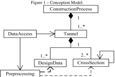
work efficiency. Each tunnel has a corresponding set of design data prior to excavation, and real survey data for each tunnel cross-section in new excavation is obtained through construction survey. The cross-section survey data and the design data are processed as a data file uploaded to the database during preprocessing, the main content of this file is to record the data from cross-sections in the new tunnel excavation. In accordance with the survey time order, a Triangular Irregular Network (TIN) is built between adjacent survey cross-sections. In this way, the dynamic construction process of a tunnel is simulated in time, and project quality of tunnel excavation can be represented. Based on these modeling ideas, a conceptual model, expressed in a simple class diagram of UML, for dynamic three-dimensional tunnel modeling was developed as shown in Figure 1:
Figure 1 – Conception Model.
1) Tunnel construction process (ConstructionProcess): this class is the gateway for queries and for management of the entire construction process simulation. It includes all tunnels in a project. Its life cycle starts before the first tunnel is excavated and ends after the last tunnel is completed.
2) Tunnel (Tunnel): this class is responsible for organizing and managing tunnel design and survey cross-sectional data. Each tunnel is composed of a set with the design data and at least two survey cross-sections, since a 3D TIN model of the tunnel section is built between at least two cross-sections.
coordinate conversion of a survey cross-section. Design data may include the design cross-section according to the actual demand.
4) Cross-Section (CrossSection): this class is responsible for organizing and managing survey cross-sections in global projection coordinates and can be used for visualization. Each cross-section must be associated with its adjacent cross-section, in order to build a tunnel model formed from TINs between adjacent cross-sections.
5) Data access (DataAccess): this class is used to quickly obtain the raw survey cross-section data in a linear coordinate system as used in engineering. The data are generally derived from a total stations in the tunneling survey process file uploaded after coordinate transformation, it provides a data source for timely adding cross-sections to a tunnel object.
6) Data preprocessing (Preprocessing): data preprocessing refers to the transformation of point coordinates in a survey cross-section for modeling. Since the tunnel cross-section survey commonly uses a linear reference system making the design centerline the axis, the coordinates of the survey cross-section must be converted based on the design centerline data in order to draw the cross-section data correctly in a global projected coordinate system.
3. KEY TECHNOLOGIES
3.1 Coordinate Transformation
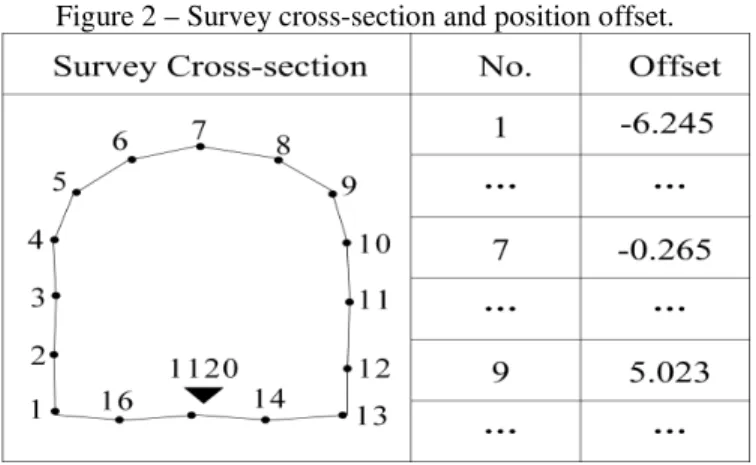
The survey data of tunnel cross-section is a set of a series of coordinate points based on a linear reference system (LAM and TANG, 2003), the form of original coordinates is Pori( , ,N O M E T, , ), where N represents serial number of point (No.), O represents offset, M represents mileage, E represents elevation, and T represents time. The offset O is a horizontal offset distance between a survey point and the design centerline of a tunnel, following the design centerline mileage direction. The offset value on left side is negative and the right side is positive. The mileage of each survey point in the same survey cross-section has a deviation when compared with the preset mileage during surveying, but the deviation is small, so the mileage M of each survey point in the same cross-section is set to the same value. Since the unified standard vertical datum is used directly when the cross-section is surveyed, the elevation E of a survey point can also be used directly, and therefore does not participate in the coordinate transformation. Figure 2 shows the tunnel survey cross-section and its position offset.
Figure 2 – Survey cross-section and position offset.
The design centerline is composed of both straight line and arc segments. The circular arc can be decomposed to arc segments. Each endpoint of segment in the design centerline contains a mileage value and the corresponding global projection coordinate values. As shown in Figure 3, a segment of the design centerline is composed of two straight line segments (AB and CD) and circular arc (BC). From the cross-section mileage, the cross-section position P in the centerline can be located in line or arc segments. Because they are calculated in different ways, different methods are needed for line and arc segment coordinate transformation.
Figure 3 – Design centerline.
In Figure 3, the axes X and Y are the two coordinate axes of the global projected coordinate system, the direction of arrow N is true north, P1 point is a
position of cross-section in a straight line segment andP2 is a position in an arc
cross-sections (S1 and S2). Along the design centerline mileage direction, the offset value
on left side is negative and the right side is positive. The two angles called
θ
1 and2
θ
are the two azimuths between two cross-sections with the direction of true north. The point O represents the center point of the arc segmentBC.1) Coordinate transformation on a straight line segment
Assuming that the survey cross-section is located on the straight line segment
AB, at point
P
1 is shown in Figure 3. Granted a plane coordinate (X YA, A)and a mileage MAat point A, the plane coordinates (X YB, B) and mileage MB of point B,and mileage 1
p
M of point P1, the process for a coordinate transformation of the
survey cross-section in the straight line segment AB is as follows:
Firstly, given these conditions, the plane coordinates XP1 and Yp1 at pointP1 are easily calculated using the straight-line interpolation formula.
Secondly, the azimuth θAB of AB is calculated according to the formula (1) (GAO and ZHENG, 2005).
(
)
2
arcsin
ABAB AB AB
X
Sgn Y
S
π
θ
= −
π
∆
+
∆
(1)In the formula (1),
∆
X
AB=
X
B−
X
A, ∆YAB= −YB YA,S
AB=
M
B−
M
AThirdly, the azimuth
θ
1 of cross-section S1 perpendicular to design centerline, is calculated according to the formula (2).1
(
AB+
π
2
)
Mod
(2 )
θ
=
θ
π
(2)
Finally, according to the plane offset of each survey point in the cross-section at mileage
P
1, the plan projection coordinates for the cross-sections are calculated by the formula (3), to complete coordinate transformation.1 1
1 1
cos
sin
i P i
i p i
X
X
Offset
Y
Y
Offset
θ
θ
=
+
×
=
+
×
(3)2) Coordinate transformation on a circular arc segment
mileage MB for point B, a plane coordinate (X Yc, c) and mileage Mc for point C, a
mileage Mp2 for point P2, a plane coordinate
(
X Y
B,
B)
at the center of the circle O of the circular arc segment, and a radianB C
θ
and a radiusBC
R
for BC, then theprocess of coordinate transformation of a survey cross-section at BC is as follows: Firstly, according to the coordinates of point B and O, azimuth
θ
BO of BO iscalculated by the formula (1).
Secondly, the arc length LBC between point B and C and the arc length is obtained from the mileages of point B,
P
2 and C. Then, the azimuthθ
2 of P O2 is calculated according to the formula (4).2
2
=(
+
)
(2 )
BP BC BO BC
L
Mod
L
θ
θ
θ
π
(4)
In the formula (4), LBC=MC−MB,
2 2
BP P B
L =M −M
Thirdly, given the radius R, the azimuth θ2, and the center of the circle O, the
plan projection coordinates
2 2
(Xp ,Yp ) of the point
P
2 are calculated by the formula(5). 2 2 2 2
cos
sin
p o p oX
X
R
Y
Y
R
θ
θ
=
−
= −
(5)Finally, according to the plane offset of each survey point in the cross-section at the mileage
P
2, the plan projection coordinates in the cross-sections are calculated by the formula (3), to complete the coordinate transformation.After the coordinate transformation, the standard coordinate form
( , , , , )
std
P N X Y E O of the cross-section survey data is obtained. In the form, N represents a point number (No.), X and Y represent two components of a plane rectangular coordinate system, E represents an elevation, O represents a plane coordinate offset in the linear coordinate system.
3.2 Data Storage Structure
adjacent cross-sections, and the dynamic simulation of a tunneling process (WANG and LU, 2011).
The adjacency relationship between the cross-sections is related to the tunneling direction, and not directly related to the mileage of each cross-section. The first excavated portion is a front, and the last excavated portion is the back portion. As shown in Figure 4, assuming the left side of each graph is the starting point (i.e. mileage value is 0) and the right side is the endpoint (i.e. mileage value is maximal). Figure 4(a) shows tunneling along mileage direction from the position at mileage 0, Figure 4(b) shows tunneling along inverse mileage direction from the position at maximum mileage, Figure 4(c) shows tunneling along mileage direction from the position at an intermediate shaft, and Figure 4(d) shows tunneling along inverse mileage direction from the position at an intermediate shaft. The actual tunneling process can be one of them, or any combination of the various types. Because a group of tunnel cross-sections are surveyed in time at set intervals, and the cross-section data is uploaded after processing, each upload file contains a group of sequential and adjacent tunnel cross-sections.
Figure 4 – Tunneling direction: along mileage direction from mileage 0 (a), along inverse mileage direction from maximum mileage (b), along mileage direction from an intermediate shaft (c) and along inverse mileage direction
from an intermediate shaft (d).
(a) (b)
(c) (d)
Figure 5 – The cross-section data structure of uploaded file.
In Figure 5, Mirepresents a mileage of the current cross-section, Ti represents the time of the current cross-section, Mi−1 represents a mileage of the current front adjacent cross-section (only the first cross-section of each uploaded file has this option), Mi+1 represents a mileage of the back adjacent cross-section of the current
cross-section, N X Y E O1, 1, ,1 1, 1 respectively represent serial number, coordinate X, coordinate Y, the elevation value E and linear coordinate offset O at the first point of this cross-section, N X Y E O2, 2, 2, 2, 2 represent respectively the serial number, coordinate X, coordinate Y, elevation value E and linear coordinate offset O in the second point of this cross-section, and END represents the data description completion for the current cross-section. If there is a following cross-section, then the structure is repeated, until all the cross-sections uploaded at this time are described. If the cross-section is the first cross-section in the uploaded file, and does not have (temporarily or not) a front adjacent cross-section, then Mi−1=NULL; If the cross-section is the last cross-section in this uploaded file and has no (or temporarily no) back adjacent cross-section, then Mi+1=NULL.
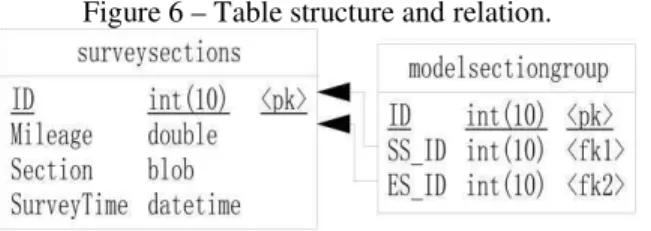
In the database, two core tables are created for storing tunnel survey cross-sections, they are SurveySections and ModelSectionGroup. The first table is used to store the basic data for a cross-section, and the second table is used to store adjacency relations between the cross-sections. Figure 6 shows the main table structures and relations.
Figure 6 – Table structure and relation.
value M of the current cross-section, Cross-section is used to store the serial numbers and 3D coordinates of all survey points in the current cross-section using a BLOB field in binary form; and SurveyTime is used to store survey time of the current cross-section. In the table ModelSectionGroup, ID represents the current adjacent relation as an automatically numbered form, SS_ID (StartSection_ID) and ES_ID (EndSection_ID) are used to store IDs of two adjacent cross-sections along the tunneling direction, the ID is dependent on the ID in the table SurveySections.
Some previous designs directly write the adjacent relation to the table SurveySections as a field, the next and/or the prior ID of cross-section is recorded in this field. But the design has two problems: first, the adjacent relation field for other records must be updated when a cross-section is added or deleted. This presents a threat to the consistency management of the database; second, each record contains coordinate point data for the cross-section survey points. The amount of data is very large, leading to inefficiencies when querying adjacency relations. However, the survey data and adjacency relations of the cross-sections are managed separately, when a cross-section is added or deleted. The operation is only associated with adding or removing cross-section data in the table SurveySections, while the adjacent relation between adjacent cross-sections is expressed clearly in the lightweight table ModelSections. These table structures for database storage can flexibility manage uploaded survey data for cross-sections, and provides support for the following dynamic 3D modeling.
3.3 Dynamic 3D Modeling
Firstly, the cross-section data set is queried for a given time range in the database table SurveySections and ModelSectionGroup; secondly, each group cross-sections (SS_ID, ES_ID) are sorted by the SurveyTime of ES_ID in ascending order; finally, each group cross-sections (SS_ID, ES_ID) are successively modeled using the triangulated irregular network (TIN), thus realizing dynamic 3D modeling for tunneling survey data.
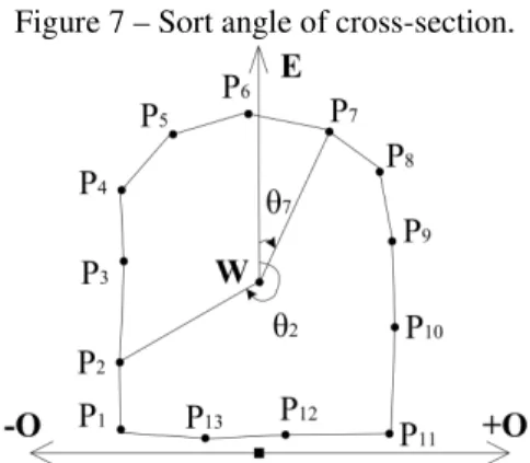
After querying survey cross-sections from the database, each survey point in the cross-section is sorted in order to build TIN between the adjacent cross-sections. An angle sort method was used in this research, the angle is determined in the coordinate plane constituted by the directions of the horizontal offset O and elevation E, as shown in Figure 7.
In Figure 7,
P
i represents a survey point in tunnel wall, i represents serial number of the survey point; and W represents geometric center of all survey points in the cross-section. Its coordinates are W O E( ,i i) in which Oi represents thecoordinate average of all survey points in the cross-section and Ei represents the
The angle between each survey point and the reference direction is calculated in the clockwise direction, such as θ7 and θ2 et al.
Figure 7 – Sort angle of cross-section.
A plane rectangular coordinate system is built using the mileage value M and direction angle value
θ
, and then each group cross-section (SS_ID, ES_ID) is drawn to the coordinate system. On this basis, a TIN model is built between the adjacent cross-sections, as shown in Figure 8. P0X represents each survey point in the cross-section in which the mileage value is 255, and P1X represents each survey point in the cross-section in which the mileage value is 260.Figure 8 – Building TIN.
All survey points in the two cross-sections are inserted respectively to their queues (Q0 and Q1) according to a value of direction angle with an ascending sort. For ease of calculation, the direction angle of the tail node in each queue is constituted by adding 2
π
to the direction angle of their head node, such as P00′ and10
calculated, according to the following steps: 1) The head node of queue is output from the queue, such asP00 and P10 in Figure 8; 2) The head node with smaller
direction angle is found in the two new queues, such as P01; 3) The angle difference
between the head node P11 of the other queue Q1 and the head node P01 of this queue Q0 is calculated, the angle difference between P01 and the node P10 that just
output of the queue from Q1 is also calculated, and an absolute value of difference between the two differences is calculated using the formula
11 01 01 10
1 ( p p ) ( p p )
y =
θ
−θ
−θ
−θ
; 4) The head nodeP
01 with smaller direction angle in step 3) is replaced by the node P00 which is outputted from queue Q0, then thesame calculation is performed using the formula
11 00 00 10
0 ( p p ) ( p p )
y =
θ
−θ
−θ
−θ
; 5)The two difference absolute values (
y
0 andy
1) are compared, ify
1 is the smallerone, the head node
P
01 of the queue Q0 and the two nodes (P00 and P10) arecombined to form a triangle ∆P P P00 10 01, then P01 is outputted from the queue; if
y
0is smaller o, the head node P11 of the other queue Q1 and the two nodes (P00 and
10
P ) are combined to form a triangle ∆P P P00 10 11, then P11 is outputted from the queue; 6) Repeat steps 2) through 5) until all nodes in the two queues are output from the queue. Some researchers have built TIN triangles based on the principle of minimum direction angle, without the calculation and logical steps 3), 4), and 5) of the algorithm presented in this article. As shown in Figure 8, ∆P P P03 04 11 and
11 12 04
P P P
∆ are generated when the four points (P03, P04, P11, and P12) are connected, but
∆
P P P
11 12 03 and∆
P P P
03 04 12 are generated using the proposed method. This method is defined as the optimized minimum direction angle algorithm. The current TIN generation algorithms for tunnels apply the TIN generation algorithm with the same number nodes (XU et al., 2008; LV and ZOU, 2011), however, the Constrained Delaunay Triangulation algorithm (CD-TIN) (LI et al., 2011), and constrained triangulation net generation algorithm between the adjacent cross-sections (CHEN, 2009), are excessively restrictive and not flexible enough, with a computational cost that is too large.Figure 9 – The TIN stereogram between the adjacent cross-sections.
4. IMPLEMENTATION AND DISCUSSION
4.1 Implementation
In order to speed up the progress of a project, construction teams excavate from both ends to middle of the diversion tunnel. The construction survey team used the electronic total station to survey tunnel cross-sections along the design centerline for new excavation at set intervals (GE and WANG, 2006). The raw survey data are ultimately transformed into a dynamic 3D model through software processing. In practical applications, it is often necessary to build a 3D model of the construction survey data to represent the construction progress and quality of the project, and a complete software system must be established for decision support managers (JIA et al., 2008; CUI et al., 2010).
Using the proposed model, a diversion tunnel project for an embankment dam hydropower station in western China is taken as an experimental example, so as to use the construction survey data in a dynamic system for better effect. The system architecture is shown in Figure 10:
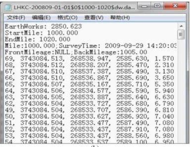
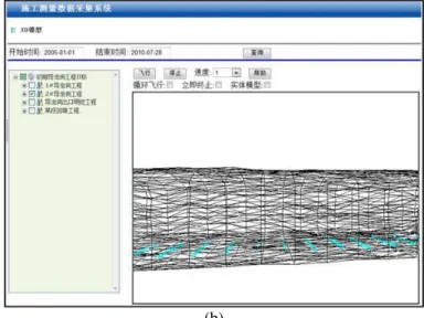
The construction survey data acquisition and dynamic system consists of three major components. The first is the data access and processing subsystem based on the AutoCAD development platform; this subsystem is responsible for accessing and processing cross-section survey data. It transforms the raw data into the form of linear coordinates exported from all the stations into global projection coordinates. The data are stored in a DAT file with a prescribed structure, as shown in Figure 11. The second is a Web management subsystem, the subsystem is responsible for the importing the standard data files, data management, and dynamic 3D modeling. A Web site was developed with Visual C# 2008 ASP.NET is used to import and manage data, and an ActiveX control developed with Visual C++ 2008 is used for the dynamic 3D modeling. The control is embedded on some pages of the Web site and responsible for dynamic 3D modeling and model visualization. It shows the progress and quality of construction. The visual effect delivered by dynamic modeling is shown in Figure 12. The last component is the data storage and distribution subsystem. This subsystem uses MySQL as the database management system and directly provides data to the Web site. A WebService was developed with Visual C# 2008 providing data for modeling and visualization to the ActiveX control.
Figure 11 – Preprocessing data: the raw survey data (a), the uploaded data after pretreatment (b).
(b)
Figure 12 – Dynamic modeling visualization: Time
t
1(form start time to02-06-2010) (a), Time
t
2(form start time to 28-07-2010) (b).(b)
A comparison of the two graphs in Figure 12, intuitively illustrates the progress of a tunnel project, as well as the construction quality. The 3D ActiveX control can also be used to fill the tunnel TIN model to better visualize the external and internal forms of tunnel, as shown in Figure 13.
Figure 13 – The forms of tunnel: External form (gray part is built by survey cross-section) (a), Internal form (indigo part is built by design
cross-section) (b).
(b)
Tunnel section is dynamically built with the 3D ActiveX for accurately representing the quality of tunnel excavation. The overbreak and underbreak are decided according to the actual excavation line compared with the design cross-section line and the maximum allowable overbreak line, so the tunnel excavation quality can be represented. A tunnel cross-section graph is shown in Figure 14.
Figure 14 – Dynamically build a tunnel cross-section graph.
4.2 Discussion
and data management systems, the proposed method has the following characteristics:
1) A stable data source
In order to compute the amount and progress of the tunneling process, newly excavated parts need to be surveyed by the survey team at least once a month. The construction survey data is processed into cross-section graphs. Dynamic 3D modeling data can be easily be extracted from the construction survey data through coordinate transformation without resurveying.
2) An optimized TIN modeling method
An optimized minimum direction angle algorithm is proposed for building 3D tunnel models, this method increases rationality when building TIN between two cross-sections.
3) Fast dynamic modeling
Construction survey cross-section data is uploaded into a database after it has been processed in a specified format. A tunnel 3D model can be automatically built by using query conditions in the data management system without human intervention. This modeling method is simple and efficient, while tunnel excavation progress can be viewed as a time sequence.
4) An integrated structure for the data management system
The construction survey data management system has an integrated functional system, from data preprocessing, to data upload, to data storage, to data query, and to data visualization.
5) High application value
Real construction survey data is stored and managed, providing a reliable data source for this application and other applications; the survey data is stored in the database instead of files, for be easily query; the excavation progress and quality is expressed intuitively through visualization.
5. CONCLUSION
At present, in order to show the dynamic tunneling process some researchers often increase the time information from the design data to support a 3D tunnel model. This research instead uses real survey data to dynamically build a 3D tunnel model, responsive to tunneling progress, but also expressing tunneling quality.
construction survey data collection and dynamic modeling system was designed and realized based on this conceptual model and the core technologies, in which the progress of project and the quality of construction can be easily and quickly expressed.
This paper argues that this system is dynamic in three areas: Firstly, the data sources are dynamic, providing relevant data in a quickly, timely and accurate manner, as well as a means to update the data at any time. Secondly, the data modeling is dynamic, meaning that the data, stored in the database, is not created in advance for 3D model, but that the 3D tunnel model is in a TIN form and built dynamically using the survey points of cross-sections. Thirdly, dynamic visualization, in accordance with the survey time in ascending order, the mining process is shown dynamically. All of this ensures the authenticity of the data, but also model building flexibility, and timeliness of visualization, to provide decision support for managers.
This paper only relates to dynamic data modeling during tunnel excavation, morphological tunnel modeling after lining will be realized in the future, as quality evaluation of tunnel engineering and dynamic texture mapping are researched in-depth. Other data sources, including Lidar data will also be used for dynamic modeling of the tunneling process (SHINTARO et al., 2012).
ACKNOWLEDGEMENTS
The work described in this paper was supported by the research program of acquisition construction survey data and creation data warehouse and application system from Ertan Hydropower Development Company, Ltd. (No. LHKA-201010), and thanks for the support of The Chinese National High Technology Research and Development Program (863 Program) - The Spatiotemporal Process Simulation and Real-time GIS (No. 2012AA121401).
REFERENCES
BERBERAN, A.; MACHADO, M.; BATISTA, S. Automatic Multi Total Station Monitoring of a Tunnel. Survey Review, 39(305), 203-211, 2007.
CHE, D.F.; XIU C.H.; CHE, J.Y. A new method of tunnel 3D modeling and its applications. IEEE International Geoscience and Remote Sensing Symposium (IGARSS), Vancouver, BC, Canada, p. 2988–2991, 2011.
CHEN, L.Z. 3D Modeling Techniques of Mine Roadway. MSc. Thesis, Kunming University of Science and Technology, Kunming, China, 2009.
CUI, F.; HUANG, M.; GUI, L.X. Coal mine information system based on 3D geological roadways. International Conference on Computer Application and System Modeling (ICCASM 2010), Taiyuan, China, 11, p. 606–609, 2010. GAO, J.Q.; ZHENG, G.C. Computation of Coordinate Azimuth during Teaching of
Surveying. Modern Surveying and Mapping, 28 (5), 47–48, 2005.
GE, Y.H.; WANG, J.M. Study on Model Building in Three-dimensional Tunnel.
GIKAS, V. Three-Dimensional Laser Scanning for Geometry Documentation and Construction Management of Highway Tunnels during Excavation. Sensors, 12(8), 614-628, 2012.
JIA, R.S.; JIANG, Y.; SUN, H.M.; WEI, X.J. Research on 3D Spatial Data Model of Mine Underground Space Based on Dynamic Field Frame. Pacific-Asia Workshop on Computational Intelligence and Industrial Application (PACIIA '08), Wuhan, China, 2, p. 254–258, 2008.
LAM, S.Y.W.; TANG, C.H.W. Geometric Modeling Systems for Construction Surveying of Highway Tunnels. Journal of Surveying Engineering, 129(4), 146-150, 2003.
LI, M.; MAO, S.J.; WANG, H.; LU, B.T. 3D dynamic modeling and interactive query of underground roadway, 19th International Conference on Geoinformatics, Shanghai,China, p. 1–4, 2011.
LV, K.Y.; ZOU, S.L. Research on Mine Laneway 3D Modeling. International Conference on Electronic & Mechanical Engineering and Information Technology (EMEIT), Harbin, China, 3, p. 1545–1548, 2011.
SEO, D.J.; LEE, J.C.; LEE, Y.D.; LEE, Y.H.; MUN, D.Y. Development of cross section management system in tunnel using terrestrial laser scanning technique. Proceedings of the International Archives of the Photogrammetry, Remote Sensing and Spatial Information Sciences, XXXVII(B5), Beijing, China, p. 573-581, 2008.
SHINTARO, O.; LIANG, X.; ATSUHIKO, B.; TAKESHI, O.; YOSHIHIRO, S.; KATSUSHI, I. Global 3D Modeling and its Evaluation for Large-Scale Highway Tunnel using Laser Range Sensor. 19th ITS World Congress, Vienna, Austria, p. 1–12, 2012.
WANG, H.J.; LU, X.M. Research on the Three-Dimensional Modeling of Mine Surface Plant and Laneway. Fourth International Symposium on Computational Intelligence and Design (ISCID). Hangzhou, China, 2, p. 67– 70, 2011.
WANG, X.L.; LIU, X.P.; SUN, Y.F.; AN, J.; ZHANG, J.; CHEN, H.C. Construction schedule simulation of a diversion tunnel based on the optimized ventilation time. Journal of Hazardous Materials, 165(1-3), 933-943, 2009. WANG, Y.J.; FU, Y.M. On 3D Automatic Modeling Method of Mine Roadway.
Geomatics and Information Science of Wuhan University, 31 (12), 1097–1110, 2006.
WEI, Z.Y.; WANG B.S.; LI, Q.Y. Underground Laneway Modeling and Realization by C++. Geomatics and Information Science of Wuhan University, 30 (7), 650–653, 2005.
XU, Z.Q.; YANG, B.R.; WANG, L.G.; BI, L. Laneway entity three-dimensional modeling study and realization. Computer Engineering and Applications, 44 (6), 202–205, 2008.
YAO, J.H. Modeling Technology Study on the Three-dimensional Laneway.
ZHONG, D.H.; WANG, Z.Y.; LI, M.C.; LIU, J. 3D Geological Modeling and Dynamic Simulation Analysis to Complex Underground Structure Groups.
Journal of Computer-Aided Design & Computer Graphics, 19 (11), 1436– 1441, 2007.
ZHOU, Z.Y.; CHEN J.H.; YANG, L.B. 3D visualization modeling on geological and mining engineering in a large-sized mine. Journal of Central South University (Science and Technology), 39 (3), 423–428, 2008.