http://dx.doi.org/10.1590/S1982-21702014000100005
A NOVEL APPROACH FOR DETAIL SURVEYS BY THE
MOTORIZED GPSSIT CONCEPT IN RESIDENTIALS AREAS
AND ITS APPLICATION
Um novo enfoque para pequisas em detalhes pelo conceito motorizado GPSSIT em áreas residenciais e sua aplicação
IBRAHIM KALAYCI SERMET OGUTCU
Necmettin Erbakan Konya University Engineering Faculty
Department of Surveying Engineering Konya 42090 Turkey
[email protected]; [email protected]
ABSTRACT
This paper introduces the usage and reliability of Motorized GPSSIT technique which is a novel approach for surveying. It reviews the advantages of Motorized GPSSIT concept and also considers to provide GNSS accuracy in the process of surveying especially for the cases which cannot be surveyed directly by the satellite navigation systems (GPS-GNSS), such as closely packed residential areas, tall buildings, trees, etc., and also places which GNSS receivers cannot be work efficiently due to signal interferences. In this technique, all the survey instruments are installed on a bed of a pick-up truck whereas in present techniques they are installed on the ground, therefore it is called Motorized GPSSIT. Study area was chosen within the housing area of our campus. In this area, classical surveying, GPSSIT and Motorized GPSSIT were performed to collect data for comparison and for the analysis of this technique's usability and reliability. Stop and Go and RTK surveying techniques were performed with GPSSIT and Motorized GPSSIT concepts. It is shown that the Motorized GPSSIT technique is applicable as other present techniques in terms of accuracy and reliability.
RESUMO
Este trabalho introduz o uso e a confiabilidade da técnica motorizada GPSSIT, que é um novo enfoque para a pesquisa. Revê-se as vantagens de conceito motorizado e também considera a disponiblidade da precisão GNSS no processo de pesquisa especialmente para os casos que não foram estudados diretamente do sistema de navegação por satélite (GPS-GNSS) tais como em áreas residenciais bem fechadas, prédios altos, árvores, etc, e tambem em locais onde os receptores GNSS não podem ser operados eficientemente devido a interferência de sinal. Nesta técnica, todos os instrumentos da pesquisa são instalados numa plataforma de caminhão pick-up enquanto que nas presentes técnicas, eles são instalados no solo, e portanto são denominados como motorizados GPSSIT. O estudo foi realizado dentro de uma área construída no nosso campus. Nesta área, a pesquisa clássica, GPSSIT e motorizada GPSSIT foram realizadas para a coleta de dados para a comparação e análise da confiabilidade e usabilidade da técnica “stop and go” e técnicas de pesquisa RTK foram realizadas com os conceitos GPSSIT e motorizados GPSSIT. Foi possível demonstrar que a técnica é aplicavel como outras técnicas atuais em termos de acurácia e confiabilidade.
Palavras-chave: GPS; GNSS; Levantamentos de Detalhes; GPSSIT; Estação Virtual; GPSSIT Motorizado.
1.INTRODUCTION
Before total station came into existence as a surveying instrument, surveyors generally used theodolites and steel band or Electronic Distance Measurement (EDM) device together for angle and distance measurement in order to propagate coordinates from one point to another using the technique of traversing. The Total Station simplified the procedure of traversing by integrating the EDM into the theodolite and reading all measurements digitally (CRANENBROECK J, 2005).
Despite many advantages, surveying using only total stations or satellite positioning systems have own unique disadvantages. Surveying with a total station, unlike GPS surveying, is not disadvantaged by overhead obstructions however, it is restricted to measurements between visible points in the surveying area. Control points generally located far away from the survey area, therefore traversing with a total station to propagate the control is a time consuming task (CRANENBROECK J, 2005).
harder and adds some additional labour effort when it is compared with surveying process which receiver antenna can be applicable directly and vertically over the details (LEICK, 1990).
In this research, here in housing area of campus, to overcome these difficulties, especially to reducing time requirement for surveying, Motorized GPSSIT technique which is more practical and swift than the GPSSIT technique alone was developed. Thanks to the mobile pick-up vehicle, mobility of surveying increased and time requirement of surveying reduced dramatically compared to the GPSSIT technique alone. In GPSSIT technique, there is always need to setting up at least two levelled tribrach with tripod or generally much more without necessarily established ground-based points with known coordinates for detail surveys which cannot be surveyed directly by GNSS receiver. Motorized GPSSIT technique eliminates this dependency on the ground. After the design stage was completed, system was tested on campus area of to understanding whether it can be reliably accurate, usable and applicable in the practise.
2. GPSSIT (GPS VIRTUAL STATION TECHNIQUE)
Nowadays, we all realize that classical surveying techniques leave their places very rapidly to modern GPS and Global Navigation Satellite System(GNSS). Naturally, as other surveying techniques GNSS has own special problems in some circumstances. GNSS receivers require an unobstructed view of the sky, so they are used only outdoors and they often do not perform well within forested areas or near tall buildings(YAHYA & KAMARUDIN, 2008).
In open lands, generally, relative positioning technique is chosen. Instead of determining the position of one point on the earth with respect to the satellites (as done in single point positioning) the position of one point on the earth is determined with respect to "another" known point (SCHWARZ & SCHUBERNIGG, 1992; WYLDE & FEATHERSTONE, 1995). Generally, to providing relative positioning technique, Continuously Operating Reference Stations (CORSE) which is dependent on network based RTK have been widely used for surveyors. Network RTK is a centimetre-accuracy, real time, carrier phase-based positioning technique capable of operating over inter-receiver distances up to many tens of kilometres (the distance between a rover and the closest reference station receiver) with equivalent performance to current single base RTK systems (operating over much shorter baselines) (RIZOS, 2002). CORSE has many advantages compared the other GPS surveying techniques. For example, one receiver(rover) is enough to perform surveying without using stationary receiver so it helps surveying procedure to be more swift and easy.
the plumb line passing through these two special points and this alignment called "single tribrach combination" technique (CORUMLUOGLU & KALAYCI, 2007).
Figure 1 – GPSSIT concept.
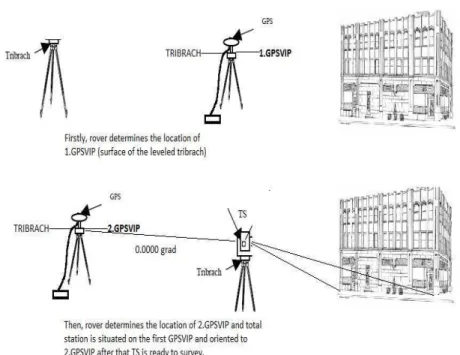
In this technique, two GPS or GNSS antenna(one stationary receiver mounted on a ground as a base station with known coordinates for relative positioning and one rover) and only one ground-based control point for base control is needed on which GNSS antenna is situated for sending correction to other receiver (rover) which is on the tribrach. In terms of Using Continuously Operating Reference Station while performing GPSSIN technique, only one GPS receiver which is a rover enough to collect observation data which mean there is no need or desire the second receiver as a stationary receiver mounted as a base station on the ground with known coordinates. The most important advantage of this technique is that like in the aerial triangulation, reference points for detail surveys are created in the air (surface of tribrach) rather than on the ground. Therefore, GPSSIT doesn't depend on any established points on the ground before the survey in terms of using CORSE system.
it is called GPSVIP (GPS Virtual Station Point) that it works as a virtual point like in the case of determination of the camera perspective center by GPS system in a GPS supported aerial triangulation process in photogrammetry (CORUMLUOGLU, 1998)
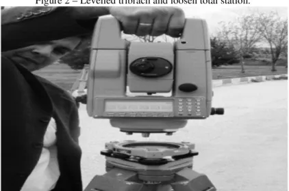
Figure 2 – Levelled tribrach and loosen total station.
Figure 3 –Putting GPS antenna on levelled tribrach.
Point(GPSVIP) of the levelled tribrach surface which is on the first tripod, after the determination of this point, rover is separated from its tribrach and situated to second levelled tribrach which is on the second tripod (second GPSVIP) and started to determine the position of second GPSVIP. Then, total station is situated on the first tribrach (first GPSVIP) which is levelled before on the first tripod, then total station is levelled more precisely via plate vial, also 3 dimensional coordinates of total station is already determined, after that total station is oriented to the second GPSVIP in order to solve geodetic azimuth between these two points. Now total station is ready to surveying for details.
Detailed descriptions on GPSSIT technique itself, Single Tribrach combination technique and surveying procedures can be found in author's preview paper (CORUMLUOGLU & KALAYCI, 2007).
3.HEIGHT DETERMINATION BY GPSSIT
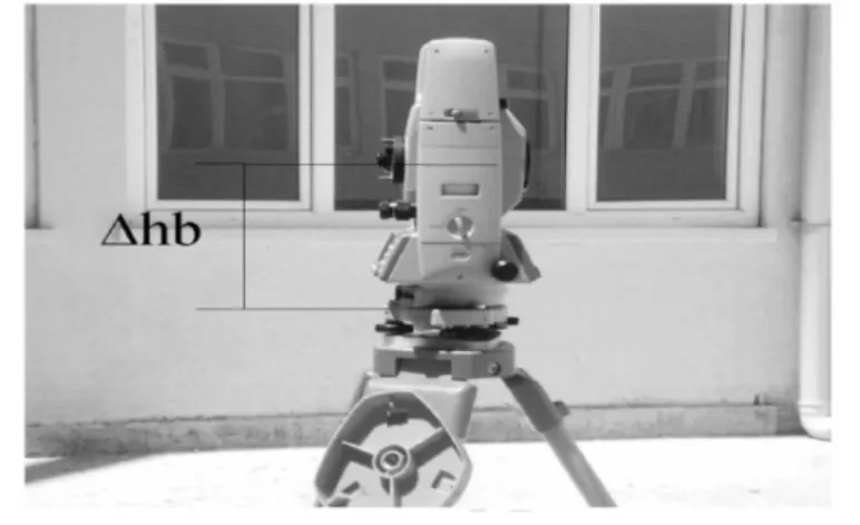
GPSSIT surveying technique is also capable of providing heights of points related the details. Therefore, in terms of height determination, GPSSIT technique is available. During the surveying process of this technique, both devices (total station and GPS receiver) uses the same levelled tribrach and should it is levelled once, surface of the tribrach remains stable during the both measurement stages of GPS receiver and total station. Therefore, reference surface of tribrach can be determined for height transformation between both devices. Using GPS antenna offset (∆ha) to determine tribrach surface height can be solved by the equation 1. Height of optical center of total station can then be determined using optical center offset of total station (∆hb) from the tribrach surface by the equation 2 (BANNISTER et all., 1992; KALAYCI, 2003). GPS antenna offset (∆ha) and optical center offset of total station (∆hb) from the tribrach surface is determined by steel tape measure with millimeter precision.
Figure 5 – Offset between optical center of total station and reference surface of tribrach.
Height transformation can be performed by these two equations:
HT=HGPS - (∆hoffset + ∆ha) (1)
HTS=HT + ∆hb (2)
where, HT is the height of the reference surface of tribrach, HGPS the height of GPS antenna phase center, ∆hoffset the constant offset value of GPS antenna (0,139 m), HTS the height of optical center of total station, ∆ha the offset between GPS antenna reference point and reference surface of tribrach, ∆hb the offset between optical center of total station and reference surface of tribrach.
4.MOTORIZED GPSSIT
for ground based GPSSIT.
First of all, GPS antenna is plugged on a tribrach with a specially designed adjustable bar that makes GPS antenna and its tribrach to be fixed on a vehicle body and GPS data can then be collected. Thus, the point called as GPS virtual point (GPSVIP) in GPSSIT is determined in 3D coordinates in this manner. Afterward, GPS antenna is removed from the tribrach and total station is attached to it. Meanwhile, GPS antenna is attached on a surveyor pole located at a place on the vehicle which is possibly far away from the tribrach on the bar. Therefore, most suitable place for the surveyor pole on the vehicle can be the most distant corner of the vehicle body, i.e. pickup. The baseline between these two points on the vehicle determined by the rover as in the GPSSI to creating reference direction for orientation of Total Station while vehicle is stopped for detail surveys. The created baseline distance on the vehicle is short. Therefore, it would inevitably cause slight orientation error for total station. Our empirical comparison shows that this error affect results in negligible level. Once GPS data collection is completed, detail surveying can be started by a surveyor without alighting from the vehicle if a laser total station is used. Once all details measurable by laser total station from the location where the vehicle is stopped, it means that first measurement section can be completed for details while vehicle is stopped on the first station then vehicle can move to another station for other measurement section and so on, until all the details are surveyed in the project area. Therefore, difficulties and time spending associated with setting up and carrying these survey instruments on the ground for each part of detail surveys can be eliminated thanks to Motorized GPSSIT technique.
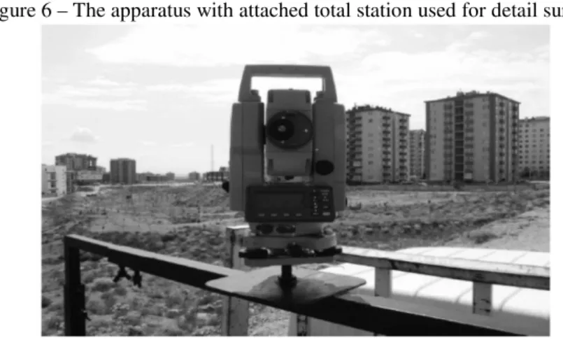
As mentioned above, the apparatus should be positioned as a telescopic steel profile to fix any vehicle body and a flat surface with screw in the middle should also put to mount GPS antenna and total station on this profile (figure 6).
As mentioned previously, another apparatus should also designed and put far away from the tribrach, corner of pick-up truck body in order to provide a reference direction for total station orientation as seen in figure 7. During the GPS measurements, Stop & Go, RTK or Network Based RTK GPS surveying techniques can be used as observation technique.
Before starting the detail survey with the total station, some precaution was taken for maintaining stability of the vehicle. For example, the hand brake was on while the surveying process and the operator tries to stand stabile while performing survey. After the precaution was taken, very small amount of vibration would occur but generally they affect the results in the order of millimeter. Therefore, the error caused by the vibration is always less than a centimeter. Our equipment's (GPS receiver) accuracy for RTK is 15 millimeter ± 2 ppm so vibration error is always inside this accuracy.
Figure 7 – Apparatus used to provide reference direction for total station orientation.
General view of both apparatus on the vehicle can be seen from the figure 8 below
5.CASE STUDIES
First application of the Motorized GPSSIT detail surveys concept was performed to collect data for housing area where the 12 flats (apartments) situated for the university employees. Stop & Go and RTK GPS observation techniques were chosen during the GPS observation sections. As techniques of detail surveys, classical polar detail surveying method, ground based and Motorized GPSSIT methods were applied with Stop & Go and RTK section, Motorized GPSSIT and Classical surveying methods were used in this area and classical one was also chosen reference surveying technique for the comparison. Therefore, horizontal and vertical accuracy related the surveyed points were computed from this comparison by using root-mean-square error (RMSE) to estimate positional accuracy (Table 1, 2,3,4,5,6).
Generally surveyed points are close from the vehicle (maximum range is 100 meters) so our device compensator is more than accurate enough for the range that we are reading the data, (SUMPTER & ASHER, 1994).
dxi =XGPSSIT - XCi (3)
dyi = YGPSSIT - YCi (4)
dzi = HGPSSIT - HCi (5)
mx= / (6)
my= / (7)
mh= / (8)
mp= / (9)
GPSSIT technique. ED50 datum was used with Classic technique without any transformation. All comparisons are done in ED50 datum.
Field data have been checked for acceptable distribution by statistical tests. Normal distribution has been observed. Since the distribution graphics take so much space so they have not been included in this paper.
The level of the errors is checked as follows;
after all the readings are done, we choose an arbitrary reading and we go ahead read this point again to make sure that previous reading and new reading are in acceptable agreement.
Table 1 – Comparison of the techniques in Stop & Go GPS surveying mode for the points which can be surveyed directly by GPS.
Methods Num. of
Details (n)
mp(cm) mh(cm)
Classic-GPSSIT 188 4,92 4,03
Classic- Motorized GPSSIT 188 5,07 4,19
GPSSIT-Motorized GPSSIT 277 4,61 3,95
Table 2 – Comparison of the techniques in Stop & Go GPS surveying mode for points which cannot be surveyed directly by GPS.
Methods Num. of
Details
mp(cm)
Classic-GPSSIT 112 5,19
Classic- Motorized GPSSIT 112 5,28
GPSSIT-Motorized GPSSIT 198 4,77
Table 3: Comparison of the techniques in RTK GPS surveying mode for points which can be surveyed directly by GPS
Methods Num. of Detail mp(cm) mh(cm)
Classic- Motorized GPSSIT 180 5,12 4,87
Table 4: Comparison of the techniques in RTK GPS surveying mode for points which cannot be surveyed directly by GPS.
Methods Num. of Details mp(cm)
Classic- Motorized GPSSIT 117 5,41
RTK or network based RTK is used which mean is there is no need to post processing of GPS observation. Therefore, RTK becomes more convenience for surveyors than other GPS observation techniques. Results from the second application area summarized in table 3.
Table 5: Application carried out in Bosna-Hersek district with RTK GPS surveying mode for points which can be surveyed directly by GPS.
Methods Num. of
Details
mp(cm) mh(cm)
Classic-Motorized GPSSIT 203 4,21 3,68
Table 6: Application carried out in Bosna-Hersek district with RTK GPS surveying mode for points which cannot be surveyed directly by GPS.
Methods Num. of
Details
mp(cm)
Classic-Motorized GPSSIT 74 4,11
6.CONCLUSION
One of the most important benefits of using Motorized GPSSIT is that makes the surveying procedure independent of ground-based traverse station which requires to setting up tripod, mounting the instrument, leveling the instrument and carrying these surveying equipments together for other part of detail surveying in the situation which satellite navigation system doesn't work efficiently. This independency also helps to eliminate some mistakes in traversing such as occupying or sighting on the wrong station or mounting total station over the points which its known position changed due to the construction or any activities around the points. Motorized GPSSIT is enormously beneficial in terms of reducing time requirement of surveying process. Motorized GPSSIT also helps to maintaining GNSS accuracy when GPS or GNSS receivers cannot be performed directly due to the some handicaps of surveying area or signal interference. By considering applicability and economical efficiency in terms of surveying period, cost and labour force, it is seen that Motorized GPSSIT is very productive technique when it is used alone with Stop & Go and/or RTK GPS observation techniques.
For the future studies, it is considered to create a much more comprehensive comparison in terms of time, cost and application with great extent of data.
ACKNOWLEDGEMENT
7.REFERENCES
BANNISTER, A., RAYMOND, S. and BAKER., R. Surveying. John Wiley and Sons, Sixth Edititon, 482 pages. (1992).
CORUMLUOGLU, O. and KALAYCI, I.: The Use of GPSSIT (GPS Virtual Station Technique) with Total Station for The Measurement of Details in Residential Areas, Survey Review, 39, 303, pp. 54-67.(2007).
CORUMLUOĞLU, O. GPS Aerotriangulation In Observation Space, Ph. D. Thesis, University of Newcastle Upon Tyne, England, 233 pp.(1998).
CRANENBROECK, J. A New Total Station Tracking GPS Satellites in a Network RTK Infrastructure Perspective, 16-21 April 2005, Cairo, Egypt.
HAMILTON, J. Dam Deformation Surveying.8th FIG Regional Conference, 26-29 November 2012, Montevideo, Uruguay.
KALAYCI, I. GPS A Study on Usability of New GPSSIT Technique for GPS Supported Detail Measurements, Ph. D. Thesis, Selcuk University, Graduate School of Natural and Applied Sciences , Konya, Turkey 106 pp.(2003). (In Turkish).
LEICK, A., GPS Satellite Surveying. John Wiley and Sons, New York.( 1990). RIZOS, C. Network RTK Research and Implementation- A Geodetic Perspective.
Journal Of Global Positioning Systems, vol.1, no:2, 144-150. (2002)
ROBERT, C. GPS For Cadastral Surveying − Practical Considerations. The national Biennial Conference of the Spatial Sciences Institute, September 2005, Melbourne, Australia.
SCHWARZ, J. and SCHUBERNIGG, M., Static, Rapid Static, Reoccupation, Stop
and Go And Kinematic Measurements. Wild GPS.( 1992).
SUMPTER, C.W. and Asher, G.W, Real-Time Kinematic GPS For Cadastral Survey. USDA Forest Service, Wyoming. (1994).
WELLENHOF, B.H., LICHTENEGGER and H., COLLINS, J.:Global Positioning System, Theory and Practice. Springer-Verlag Wien, New York. 326 pages.( 1992).
WYLDE, G. P. and FEATHERSTONE, W.E. An Evaluation of Some Stop and Go Kinematic GPS Survey Options. Australian Surveyor, 40, 205-212.( 1995). YAHYA MH., KAMURIDIN MN. Analysis Of GPS Visibility And Satellite −
Receiver Geometry Over Different Latitudinal Regions, 2008, Skudai, Johor, Malaysia.