1594 Brazilian Journal of Physics, vol. 34, no. 4B, December, 2004
Nitriding of AISI 304 Stainless Steel by PIII
in DC and RF Toroidal Discharges
R. Valencia
a, R. L´opez-Callejas
a,b, A. Mu˜noz-Castro
a, S.R. Barocio
a,
E. Ch´avez A
a, and O. Godoy-Cabrera
a,ba
Instituto Nacional de Investigaciones Nucleares, Plasma Physics Laboratory, Apartado Postal No.18-1027 Col. Escand´on, C. P. 11801, M´exico D.F., Mexico
b
Instituto Tecnol´ogico de Toluca, Electronics Department, Apartado Postal 890, Toluca, Mexico
Received on 5 December, 2003; revised version received on 30 April, 2004
Plasma immersion ion implantation (PIII) of stainless steels with nitrogen has been successfully used for sur-face hardening purposes. This process has been carried out inside a toroidal discharge chamber in a DC/RF plasma. The RF plasma was created by one antenna located inside the chamber, diametrically opposite to the DC electrode. The latter is polarized with 1 kV and then the discharge is controlled by varying the gas pressure before the RF signal is applied. The main plasma parameters were established by means of double electric probes yielding electron temperature values within 0.5-1.5 eV and density values within 1.5×10¹⁵to 4×10¹⁵
m−3for the DC case while 1.5-3.0 eV and 7×10¹⁴to 3×10¹⁵m−3were reached with RF assisted DC. We present in this work the experimental results obtained from a PIII process applied to AISI 304 stainless steel plates. The outcome shows that the Vickers hardness has been incremented according to the gas pressure within the 1×10⁻¹to 1
×10−3mbar range. The treated plates were analyzed by scanning electron microscopy (SEM) and the results point to an increased percentage of nitrogen, around 20%. By means of x-ray diffractometry (XRD) the gamma expanded phase and compounds such as Fe3NiN, Ni4N, FeNiN and Fe3N were determined.
1
Introduction
Plasma immersion ion implantation (PIII) is an effective sur-face modification method for treating complex shape com-ponents [1-7]. In PIII, the nitrogen ions are extracted direc-tly from the plasma in which the samples to be processed are immersed. This is achieved by applying negative high voltage pulses of 1-100 kV, of 1-100µsec duration and 100-1000 Hz repetition frequency to the sheath formed between the plasma and the sample structure. In order to achieve a thicker nitrided layer in metals, a treatment at higher tem-perature is usually preferred. The targets are directly hea-ted by the high incident ion-flux during PIII, and the target temperature can be controlled by regulating the frequency and duration of the high-voltage pulses applied to the sam-ples. This process combines conventional ion implantation and diffusion.
Austenitic stainless steels, such as AISI-304, present a relatively low hardness, in the order of 200-300 HV. There are several processes intended to increase the surface hard-ness and tribological quality without reducing the excellent corrosion resistance that makes these steels so attractive in many applications. Plasma nitriding at temperatures above 5000
C, while giving significant improvement in wear resis-tance, tends to affect adversely the corrosion performance of stainless steels due to the precipitation of CrN which remo-ves Cr from its solid solution [8].
According to the so called Tian theory [9], in a typical
PIII process, ions within the sheath are accelerated to thou-sands of eV resulting in a transient time in the order of nano-seconds; so that the sheath transient time is practically ins-tantaneous when compared to the voltage pulse, typically in the range of msec. Under low pressure conditions∼10−3
mbar range, collisionless conditions are valid and all ions within the sheath do not undergo collisions or charge trans-ference and are implanted at the applied voltage. Since the sheath voltage is always greater than the electron tempera-ture, we can assume that a quasi-static Child-Langmuir law sheath exists at all times and that the ion current is spati-ally constant within the sheath. As a result, when a negative voltage is applied to the target, a dynamic process will com-mence. The primary electrons are pushed away, an ion she-ath forms and ions are implanted into the target at an applied voltage that varies at the beginning, depending on the slew rate of the power modulator.
R. Valenciaet al. 1595
Figure 1. Cross-sectional view of the toroidal chamber, displaying the DC and RF supplies, plasma, probe and high voltage pulse supply.
2
Experimental Set-Up
The toroidal vacuum chamber selected for this work is 23 cm in major radius and 8 cm in minor radius, as shown in Fig. 1. Glow discharges in nitrogen are produced between a cylindrical stainless steel electrode (anode) and the groun-ded toroidal chamber wall. The anode is inserted within the toroidal chamber through a vertical port and it is connected to a 0-1500V/2A DC power supply through a 488 Ωload resistor intended to limit the current flow to the plasma. The negative terminal of the power supply and the toroidal cham-ber were grounded. The highest discharge current used in the experiment was 500 mA. By assuming that all the wall is exposed to the discharge, we can roughly estimate a ma-ximum current density of 70µA/cm2.
Figure 2. Dependence of the plasma density and temperature on nitrogen gas pressure.
The plasma sources we have chosen are a highly stable DC glow discharge and a 13.56 MHz RF generator positio-ned at 180 degrees from the anode DC source. A schematic view of the PIII setup is shown in Fig. 1. The plasma in the toroidal chamber was extensively characterized both in density and temperature applying the Auciello double probe method for different pressures as described in [12]. Fig. 2 shows the plasma density and the electron temperature as
functions of the nitrogen pressure, measured near the to-rus axis where the density turned out to be higher, in two plasma conditions, one under a 350V/0.2A DC only and the other under a 350V/0.2A DC+50W RF, the density remai-ning practically the same in both regimes. In such an axial neighborhood,neis greater due to locally longer electric fi-eld lines which favor ionization by collisions. For the same reason,neis increased with the working pressure, whereas
Te is decreased as observed in Fig. 2. Our results seem to be in good agreement with the typical behavior in density and temperature reported by Kojima and Park [13-14]. The sudden drop in the electron density at pressures higher than 1×10⁻¹mbar can be attributed to a lesser degree of
ioniza-tion in the gas.
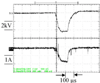
Figure 3. Implantation voltage and current waveforms: (1) voltage and (2) current.
1596 Brazilian Journal of Physics, vol. 34, no. 4B, December, 2004
In Fig. 3, the horizontal scale corresponds to 100µs per di-vision. The vertical scales are 2 kV and 1 A per division, respectively. We present some results obtained from the PIII process applying -5 kV bias pulses with a half width 100
µs long and a 1 kHz frequency during 4 hours at different pressures within the toroidal vacuum chamber.
3
Results
The process was carried out on AISI 304 stainless steel sam-ples within a pressure range between 10−1 to 10−3 mbar
and a 1.8 A current demanded from the sample. The cor-responding waveforms are displayed in Fig. 3. The sample temperature remained between 3500C and 4500C during the whole PIII process, at all the work pressures. Once the pro-cess is finished, the surfaces of the samples show a distinct roughness, not only because of the grain boundary etching but also of the deformation of the grains due to their higher nitrogen content [2]. In order to establish the degree of sur-face modification of the samples, these were characterized by means of scanning electron microscopy (SEM) as well as Vickers microhardness testing.
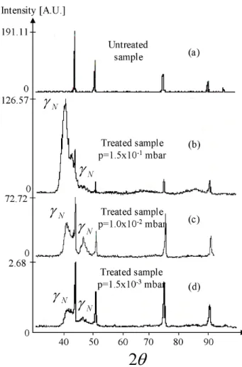
The phase transformation in the near surface is respon-sible for the change in the sample appearance, as indicated by XRD results in Fig. 4. We have used a diffractometer with CuKαradiation operated at a 35 kV acceleration and a 25mA current in order to determine the phases present in the modified layer. The analysis of the standard reference sam-ple is shown in Fig. 4a, covering a 2θinterval between 300
and 1000
. The most relevant information is found at 43.40
, 50.60
, 74.60
, 90.50
and 95.70
C. Figs. 4.(b)-4.(d) exhibit the diffractogrammes taken from one PIII treated sample at dif-ferent gas pressure intervals. In these figures, some addi-tional peaks are observed at: i) the angles 41.20
and 48.10
where roaldite (Fe3NiN) exists; ii) the angles 41.8 0
, 48.50
and 71.40
where nickel nitride (Ni4N) is found; iii) the
an-gles 400
, 45.40
, 490
, 85.50
and 86.10
where iron nickel ni-tride (FeNiN) is present, and iv) the angles 38.40, 69.60, 77.10
, 84.20
, 86.10
and 96.50
where iron nitride (Fe3N) is
located. In the same Fig. 4.(b)-4.(d), the peaks associated to the original AISI 304 stainless steel can be observed.
The broad peaks labelledγN at a 2θangles smaller than those of the untreated stainless steel sample are associated with the nitrogen rich expanded austenitic phase. γN is a metastable phase consisting of supersaturated nitrogen in a solid solution. This is a typical result in which it is possible to see the peaks corresponding to theγN phase at 2θvalues 410
and 480
as the more intense and with (111) and (200) preferential orientations, respectively. The relative intensity of theγNphase is similar to and sometimes greater than that of primary austenite indicating thatγNis thick and abundant in the near surface layer.
The thickness of the modified layer is estimated by cross-sectional metallography. The scanning electron mi-crograph in Fig. 5 shows that the thickness is approximately 4µm and the modified layer is very homogeneous and uni-form in thickness. The polyhedric structures on the right hand side of the non nitrided layer can be identified with the
grain of the untreated steel while the dark dots are mainly formed by carbon impurities.
Figure 4. Difractogrammes of treated and untreated samples at dif-ferent pressures. Amplitudes are scaled in arbitrary units.
Figure 5. Cross-sectional scanning electron microscopy (SEM) mi-crograph of the treated AISI-304 stainless steel.
R. Valenciaet al. 1597
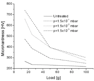
the load and suggests the presence of a thick modified layer, as showed in Fig. 5. From the results displayed in Fig. 6 follows that the best microhardness conditions are achieved at a 1.5×10⁻¹ mbar gas pressure in the chamber. Clearly,
then, the nitrogen implanted steel hardness is increased with respect to the standard untreated steel sample as well as sam-ples treated in cylindrical chambers [16].
Figure 6. Relationship between surface microhardness and inden-tation load for the PIII treated AISI-304 stainless steel with respect to the untreated reference steel sample.
4
Conclusions
A PIII experimentation on a DC/RF plasma has been carried out within a toroidal discharge chamber given the potential advantages of this geometry, in terms of longer electric fi-eld lines, over its more conventional cylindrical alternati-ves. The hardness of PIII treated AISI-304 stainless steel has been increased several times, compared to the untreated samples, due to the lattice expansion created by the super-saturation of nitrogen. This hardness increase is the most important contribution of our experiment.
We have obtained excellent results for low voltage PIII as to the improvement of microhardness. XRD data indicate that the AISI-304 sample surface has a uniform layer com-posed of expanded austenite. These results can be attributed to, among other factors, the adequate temperature control on the samples throughout the implantation process. Thus, keeping a steady range below 5000
C allowed us to improve substantially the tribological properties of the steel without spoiling its considerable corrosion resistance, associated to its Cr content.
High flux ion implantation raises the modification effi-ciency overcoming surface barriers and building up a high nitrogen concentration, rapidly enough to facilitate dopant
diffusion. It is noteworthy that, because the critical load can be considerably improved by this process, there exists a great industrial potential in it.
Acknowledgements
This work was partially supported by CONACYT under contract 39676-Y and by COSNET under contract 642.02-03-PR. The authors wish to thank the technical collaboration by M. T. Torres M. and I. Contreras V.
References
[1] J. R. Conrad, J. L. Radtke, R. A. Dodd, and F. J. Worzala, J. Appl. Phys.62, 4591 (1987).
[2] G. A. Collins, R. Hutchings, K. T. Short, J. Tendys, X. Li, M. Samandi. Coat. Technol.74-75, 417 (1995).
[3] C. Blawert and B.L. Mordike, Surf. Coat. Technol.116-119, 352 (1999).
[4] X. B. Tian, Z. M. Zeng, B. Y. Tang, and P. K. Chu, Thin Solid Films366, 150 (2000).
[5] X. B. Tian, Y. X. Leng, T. K. Kwork, L. P. Wang, B. Y. Tang, and P. K. Chu, Surf. Coat. Technol.135, 178 (2001).
[6] M. Ueda, G. F. Gomes, L. A. Berni, J. O. Rossi, J. J. Barroso, A. F. Beloto, E. Abramof, and H. Reuther, Nucl. Instr. and Meth. Phys. Res. B161-163, 1064 (2000).
[7] I. H. Tan, M. Ueda, R. S. Dallaqua, J. O. Rossi, A. F. Beloto, E. Abramof, Y. Inoue, and O. Takai, Plasma Sources Sci. Te-chnol.11, 317 (2002).
[8] Z. L. Zhang and T. Bell, Surf. Eng.1, 131 (1985).
[9] X. Tian, B. Tang, and P. K. Chu, J. Appl. Phys.86, 3567 (1999).
[10] B. C. Zhang and R. C. Cross J. Vac. Sci. Technol. A16(4), 2016 (1998).
[11] K. Hiramatsu and S. Takamura, Jpn. J. Appl. Phys.31, 2243 (1992).
[12] O. Auciello and D:L: Hamn, Plasma Diagnostic, Vol I, Dis-charge Parameters and Chemistry, Academic Press, New York, (1989).
[13] H. Kojima, H. Kako, M. Terada, H. Sugar, and T. Okuda, Jpn. J. Appl. Phys.24, 1432 (1985).
[14] Ch. H. Park, Y. M. Sung, and W. G. Lee, Thin Solid Films 312, 182 (1998).
[15] X. B. Tian, Z. M. Zeng, B. Y. Tang, T. K. Kwork, and P. K. Chu, Surf. Coat. Technol.128-129, 226 0.2in(2000).