Experimental Characterization of a Low-Current Cutting Torch
H. Kelly
1∗, B. Mancinelli
2, L. Prevosto
2, F.O. Minotti
1*, and A. M´arquez
1*
1Instituto de F´ısica del Plasma (CONICET), Departamento de F´ısica,Facultad de Ciencias Exactas y Naturales (UBA) Ciudad, Universitaria Pab. I, (1428) Buenos Aires, Argentina
2Universidad Tecnol´ogica Nacional, Regional Venado Tuerto, Castelli
501, Venado Tuerto, Pcia. Santa Fe, Argentina
Received on 19 December, 2003; revised version received on 28 April, 2004
An experimental characterization of a low-current (30-40 A) cutting torch is presented. To avoid contamination of the plasma arc by removed anode material, a rotating steel cylinder was used as the anode and the arc was anchored onto the cylinder lateral surface. The cathode-anode and cathode-nozzle voltage drops, together with the gas pressure in the plenum chamber were registered for different values of the mass flow rate injected into the plenum chamber. By employing an optical system with a large magnification (≈15 X), the arc radius at the nozzle exit was also determined with a digital optical camera. The obtained experimental quantities were used to evaluate several flow properties at the nozzle exit (hot arc plasma and cold gas temperatures, arc and gas velocities, etc.) by employing a simplified theoretical model for the plasma flow in the nozzle. The obtained results are in reasonable agreement with the data reported in the literature by other authors. Explanations of the origin of the clogging effect and the nozzle voltage are also presented.
1
Introduction
The plasma arc cutting process employs a transferred elec-tric arc between the cathode within a plasma torch and the work piece acting as the anode. A high quality cut requi-res a high velocity plasma jet. That plasma is created by a narrow constricting nozzle inside the torch, into which the gas-plasma system is injected at a high pressure. The fine-ness of the nozzle creates a large voltage drop in the plasma along its length, providing intense heating of the plasma-gas particles and associated pressure gradient forces, which accelerate the fluids to large velocities[1]. Melting and va-porization of the work piece produces the cut, followed by material displacement along the jet path.
In spite of the widespread application in industry of the plasma arc cutting process, a comprehensive description of this phenomenon has received relatively little research at-tention. Ramakrishnan et al[2, 3] measured the arc voltage, the cathode-nozzle voltage, the gas pressure at the nozzle’s entrance (the so-called plenum chamber) and the diameter of the plasma jet emerging from the nozzle as functions of the torch arc current (in the range 40-160 A). The authors presented also a simplified two-zone fluid model in which all the discharge current was assumed to circulate through a hot central core inside the nozzle, while the remaining struc-ture consisted in a relatively cold neutral gas that thermally insulates the nozzle wall from the arc. Assuming sonic con-ditions at the nozzle exit and a uniform value for the electric field, integral mass and energy balance equations were sta-ted and solved for the exit pressure, arc radius and nozzle po-tential. A reasonable good agreement with the experimental results was obtained for an arc temperature of 25000 K and
a gas temperature of 3000 K. Nemchinsky[4] presented also pressure measurements at the plenum chamber for different arc currents (in the range 100-400 A) and compared his re-sults with a more detailed two-zone model to describe the plasma-gas flow in the nozzle. Pardo et al[5] measured the arc voltage as a function of the arc current (in the range 50-180 A) for different nozzle-anode distances and determined radial profiles of the plasma temperature and density from a spectroscopic method (line emission from the arc, assu-ming an optically thin plasma). Typical plasma temperature obtained in this work at the arc center and immediately be-low the nozzle exit were from 22000 to 25000 K for 150 A, from 18000 to 20000 K for 100 A, and from 14000 to 17000 K for 50 A. Recently, Freton et al[6] presented an experi-mental and theoretical study of a plasma cutting torch using, in one experimental configuration, a rotating circular disk anode to whose lateral surface the arc was anchored. From spectroscopic line intensity measurements, an arc tempera-ture of 16500 K was found on the arc axis at 1 mm from the nozzle exit for a 30 A torch.
In this work we present an experimental study of a small cutting torch with a rotating anode operated at arc currents of 30 and 40 A. The cathode-anode and cathode-nozzle voltage drops, together with the gas pressure in the plenum chamber are registered for different values of the mass flow rate in-jected into the plenum chamber. By employing an optical system with a large magnification (≈15 X), the arc radius at the nozzle exit is also determined with a digital optical camera. The obtained experimental quantities are used to evaluate several flow properties at the nozzle exit (hot arc plasma and cold gas temperatures, arc and gas velocities, etc.) by employing a simplified theoretical model for the
plasma flow in the nozzle [7]. The obtained results are in reasonable agreement with the data reported in the literature by other authors[2, 3, 4, 5, 6]. Explanations of the origin of the clogging effect and the nozzle voltage are also presented.
2
Experimental arrangement
The torch used in this study consisted of a cathode cente-red above an orifice in a straight copper nozzle (0.8 mm in diameter). The cathode was made of copper (7 mm in diameter) with a hafnium tip (∼2 mm in diameter) inser-ted at the cathode center. A flow of air cooled the cathode and the nozzle and was also employed as the plasma gas. The gas passed through a swirl ring to provide arc stability. The nozzle consisted in a straight bore (0.8 mm in diameter, 2 mm length) in a copper holder surrounding the cathode (with a separation of 2 mm). A scheme of the torch indica-ting several geometric dimensions is presented in Fig. 1. To avoid plasma contamination by metal vapors from the anode (usually the work piece to be cut), a rotating steel disk with 200 mm in diameter and 15 mm thickness was used as the anode. In this study, the anode was located at 8 mm from the nozzle exit. The arc was transferred to the edge of the disk, and the rotating frequency of the disk was equal to 90 s−1. At this velocity, a well-stabilized arc column was obtained, and practically no metal vapors from the anode were present in the arc.
8 mm CATHODE
ANODE HAFNIUM
INSERT
f= 0.8 mm 2 mm
0.8 mm
Figure 1. Scheme of the torch indicating several geometric dimen-sions.
Air was injected into the torch at a nominal pressure of 5 bar, and the pressure in the plenum chamber (pN) was also measured by connecting a second pressure meter to the cathode-nozzle region through a small hole performed on the lateral surface of the nozzle holder. A mass flow meter was located at the entrance of the torch, but to obtain precise measurements of the mass flow through the nozzle a second mass flow meter was installed at the nozzle exit (with the arc extinguished) in order to take into account eventual gas leakages in the holders of the cathode, swirl ring and nozzle. During arc operation the voltage drop between cathode and anode (∆VAC) and between cathode and nozzle (∆VN C) were registered. By employing a converging lens with 50 cm of focal length, a highly magnified image (15X) of the plasma jet at the nozzle exit was obtained on a screen. That
image was subsequently registered with a digital camera in order to obtain a measure of the plasma radius at the nozzle exit. In Figs. 2 a sketch of the experimental set up is presen-ted. Fig. 2a) indicates the electrical and mechanical diag-nostics, while Fig. 2b) presents a lateral view of the optical diagnostic.
DVAC
DVNC
pN
ROTATING ANODE
DISK ARC
PLASMA TORCH
DIGITAL CAMERA CONVERGING
LENS
SCREEN
MAGNIFIED IMAGE (15X) OF THE ARC
a)
b)
Figure 2. Sketch of the experimental set up. Fig. 2a) indicates the electrical and mechanical diagnostics, while Fig. 2b) presents a la-teral view of the optical diagnostic.pN indicates the gas pressure
in the plenum chamber, and∆VACand∆VN Cthe cathode-anode
and cathode-nozzle voltage drops, respectively.
The arc was operated at currents (I) with values of 30 and 40 A. For a givenIvalue, the mass flow rate (dm/dt) th-rough the nozzle was varied in the rangedm/dt= 0.06 - 0.13 g/s forI= 30 A, anddm/dt= 0.05 - 0.1 g/s forI= 40 A.
3
Results
Within the frame of this interpretation, the pressure drop pA−∆p−pimeasured at the moment the arc is quenched (see Fig. 3) is a measure of the gas heating in the cathode-nozzle region during the discharge.
pN
Atmospheric pressure
Dp
pi
pA
t
Arc ignition Arc quenching
Figure 3. Qualitative plot of the time evolution of the plenum chamber pressure (pN).
A) B)
a) b)
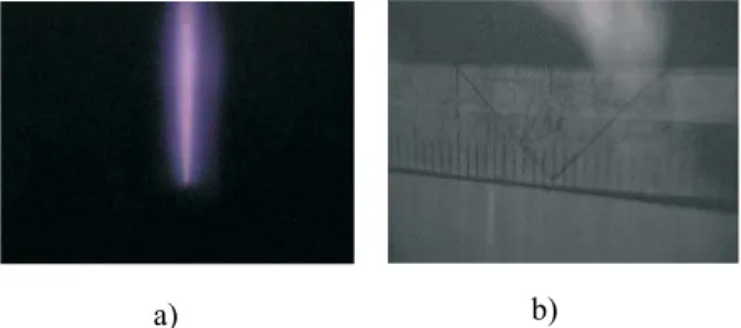
Figure 4. Fig. 4a) Image of the arc registered by the optical system. Since the lens invert the image, the nozzle exit corresponds to the bottom of the figure, while the lateral surface of the rotating disk is located at the top. Fig. 4b) Image of a graduate scale located at the same arc position.
In Fig. 4a) an image of the arc registered by the previ-ously described optical system is presented. Since the lens invert the image, the nozzle exit corresponds to the bottom of the figure, while the lateral surface of the rotating disk is located at the top. Fig. 4b) shows an image of a graduate scale located at the same arc position, which was employed to calibrate the size of the arc images. The arc emerges from the nozzle with a radiusrA= (0.3±0.1) mm, independent of the investigated values ofIanddm/dt. The relatively large uncertainty in therAvalues is due to the pixel’s size of the digital camera together with some difficulty in the determi-nation of the arc edge.
In Table I the results of the measurements ofpi,pA,∆p, pA-∆p-pi,∆VAC, and∆VN Cas functions ofdm/dtand forI= 30 A and 40 A are presented.
It can be seen from Table I that, as expected,piincreases withdm/dt, and correspondinglypApresents the same beha-vior withdm/dt. However, ∆p, which accordingly to the interpretation previously pointed out is related to the obs-truction of the nozzle’s bore by the arc, presents also an in-creasing behavior withdm/dt, that can not be explained in terms of variations ofrA (rA ≈const.). We will show in the next section that the variations in∆pcan be explained in terms of changes in the values ofdm/dtwhen the arc is in operation. It is worth noting that the measured values of
dm/dtin Table I correspond to a situation in which the arc is extinguished, so when the arc is operated (and partially obstruct the nozzle’s bore) the true value ofdm/dt(dm/dt)A) can be somewhat changed.
It can also be seen from Table I that the arc voltage drop ∆VAC reaches relatively high values, consistent with the large cathode-anode gap (≈11 mm) settled in this experi-ment. ∆VAC also present relatively small variations with dm/dt, which can be explained in terms of small variations in rA(smaller than the experimental uncertainty ofrA, because ∆VACis quite sensitive to changes inrA,∆VAC∼r−A2) or variations in the arc temperature. The cathode-nozzle vol-tage drop also presents an increasing behavior with dm/dt (similar to the behavior of∆VAC), and an explanation of these values will be given in the next Section by using the Quick Field electromagnetic program[8].
4
Discussion
In order to interpret the experimental results presented in the previous section, some of them were compared with theore-tical results obtained from a simplified hydrodynamic mo-del for the arc in the torch nozzle[7]. That momo-del uses a two-zone approximation (a hot central plasma carrying the discharge current surrounded by a relatively cold gas that thermally isolates the nozzle wall from the plasma) and al-lows to obtain the profiles of the physical quantities along the nozzle in terms of the externally controlled parameters of the torch (geometry of the torch, discharge current, mass flow of gas and plenum pressure) and the values of the arc and gas temperatures at the nozzle entrance.
In our experimental situation, the gas temperature (TG) at the nozzle entrance (x= 0) was determined from the pres-sure increase,pA -∆p-pi, which as discussed previously, is associated to the gas heating. It resultsTG(x= 0) = 370 K (that is, 70 K over the ambient temperature). The arc temperature (TA) at the nozzle entrance was employed as a parameter of the problem and was finally chosen so as to ob-tain values of the arc temperatures at the nozzle exit similar to those reported in the literature[5, 6] for similar operating current-values torches.
TABLE I: Measurements of plenum chamber pressure without arc (pi), plenum chamber pressure with arc (pA), change in the pressure due
to nozzle bore obstruction (∆p), change in the pressure due to gas heating (pA-∆p-pi), arc voltage drop (∆VAC), and cathode-nozzle
voltage drop (∆VN C) as functions of the gas mass flow rate (dm/dt) and forI= 30 A and 40 A.
I
(A)
dm/dt
(g/s)
pi (bar)
pA
(bar) D
p
(bar)
pA-Dp-pi (bar)
DVAC (V)
DVNC (V)
30 0.057
±
0.005 1.05±
0.05 1.5±
0.05 0.20±
0.1 0.20±
0.1 125±5 21±
30.077
±
0.005 1.1±
0.05 1.7±
0.05 0.4±
0.1 0.20±
0.1 135±5 22±
30.096
±
0.005 1.25±
0.05 1.8±
0.05 0.4±
0.1 0.20±
0.1 135±5 23±
30.130
±
0.005 1.3±
0.05 2.15±
0.05 0.7±
0.1 0.20±
0.1 145±5 30±
340 0.052
±
0.005 1.05±
0.05 1.45±
0.05 0.25±
0.1 0.20±0.1
124±5 18±
30.077
±
0.005 1.1±
0.05 1.75±
0.05 0.4±
0.1 0.20±
0.1 135±5 22±
30.104
±
0.005 1.25±
0.05 2.2±
0.05 0.8±
0.1 0.20±
0.1 144±5 27±
3TABLE II: Theoretical results obtained from the model. In all the casesTA(x= 0) = 10000 K, andx=Lindicates the nozzle exit. The arc
radius at the nozzle entrance was selected so as to reach an almost constant arc radius at the nozzle exit of 0.32 mm (in accordance with the measured value), and the theoretical solution corresponds to a sonic point of the arc at the nozzle exit. The quantity =dm/dt)G/dm/dt)A
indicates the mass flow fraction carried by the gas,RAindicates the arc radius,uAanduGthe arc and gas velocities and∆Vthe voltage
drop along the nozzle.
I (A)
pA(0) (bar)
dm/dt)A
(g/s)
x RA(0)
(mm)
RA(L) (mm)
uA(L) (m/s)
uG(L) (m/s)
TA(L) (K)
TG(L) (K)
pA(L) (bar)
DV
(V) 30 1.50 0.029 0.80 0.38 0.32 3700 670 18800 1680 0.98 21
1.70 0.038 0.83 0.37 0.32 3400 610 18300 1360 1.13 22 1.80 0.050 0.87 0.37 0.31 3300 560 18400 1070 1.22 22 2.15 0.070 0.90 0.36 0.31 2400 460 18200 870 1.75 22 40 1.45 0.026 0.83 0.38 0.32 5500 830 26300 1950 0.80 22 1.75 0.038 0.85 0.38 0.32 5000 740 23000 1400 1.00 25 2.20 0.055 0.85 0.37 0.32 4400 650 19800 1100 1.20 27
In Table II the theoretical results obtained from the mo-del are presented. In all the casesTA(x= 0) = 10000 K, and x=Lindicates the nozzle exit. The arc radius at the nozzle entrance was selected so as to reach an almost constant arc radius at the nozzle exit of 0.32 mm (in accordance with the measured value), and the theoretical solution corresponds to a sonic point of the arc close to the nozzle exit. The quan-tityξ=dm/dt)G/dm/dt)A indicates the mass flow fraction carried by the gas,RA indicates the arc radius,uA anduG the arc and gas velocities and∆Vthe voltage drop along the nozzle.
From Table II, it can be seen that the neutral gas car-ries the main part of the mass flow (between 80 and 90 %). The arc velocities are in the range of several thousands of m/s, while the gas velocities are in the range of several hun-dreds of m/s (both velocities present a decreasing behavior withdm/dt)A). The arc temperatures at the nozzle exit re-ach values in the range 18000-26000 K (increasing with the arc current), while the gas temperature is in the range 800-2000 K (increasing withI and decreasing withdm/dt)A). The pressure at the nozzle exit is close to 1 Atmosphere, excepting the case were a large mass flow is injected into the nozzle (fourth row in the Table) thus producing a high
pressure value at the nozzle exit. In this case, the emerging flow matches the atmospheric pressure value by a rarefac-tion wave[5]. The nozzle voltage drop∆Vranges from 21 to 27 V, and the product∆V Irepresent the Joule power de-livered into the nozzle.
is characteristic for high-pressure arcs, where the cathode electron emission mechanism is mainly thermo ionic, there-fore requiring a relatively small sheath voltage drop to pro-vide the discharge electrons[9]. Quick Field calculations for other cases gave similar agreement with the experimental cathode-nozzle voltage.
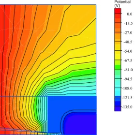
Potential (V)
0.0
-13.5
-27.0
-40.5
-54.0
-67.5
-81.0
-94.5
-108.0
-121.5
-135.0
Figure 5. Lines of constant electrostatic potential obtained from the Quick Field program for the caseI= 30 A,dm/dt)A= 0.05 g/s,
∆VAC= 135 V. Only half of the device is shown, the lower
boun-dary of the figure corresponding to the axis of the system. The block at -135 V in the lower right side represents the cathode. The equipotential block, of rectangular external boundary, around the cathode represents the nozzle. The anode, at 0 V, corresponds to the left boundary. The arc runs along the axis (lower boundary) between cathode and anode.
5
Final remarks
An experimental characterization of a low-current (30-40 A) cutting torch has been presented. To avoid contamination of the plasma arc by removed anode material, a rotating steel cylinder was used as the anode and the arc was anchored onto the cylinder lateral surface.
The cathode-anode and cathode-nozzle voltage drops, together with the gas pressure in the plenum chamber were registered for different values of the mass flow rate injected into the plenum chamber. By employing an optical system with a large magnification (≈ 15X), the arc radius at the nozzle exit was also determined with a digital optical ca-mera. The time evolution of the plenum chamber pressure
indicates that the clogging effect can be separated into two comparable contributions; one of them is due to the nozzle bore obstruction by the presence of the arc, while the other is due to gas heating in the plenum chamber.
The results of this experiment show that care must be ta-ken for the determination of the actual gas mass flow rate, either by taking into account the gas leakage in the torch when that mass flow is measured with the arc operating, or by evaluating the effect of the nozzle bore obstruction on the flow rate when this quantity is measured with the arc extin-guished.
The obtained experimental quantities were used to eva-luate several flow properties at the nozzle exit (hot arc plasma and cold gas temperatures, arc and gas velocities, etc.) by employing a simplified theoretical model for the plasma flow in the nozzle. The obtained results are in reaso-nable agreement with the data trend reported in this experi-ment or with several data reported in the literature by other authors.
Acknowledgements
This work was supported by a grant from the Universi-dad de Buenos Aires (PID X214).
References
[1] R. C. Fernicola, Weld. J.77, 52 (1998).
[2] S. Ramakrishnan, M. Gershenzon, F. Polivka, T. N. Kearny, and M. W. Rogozinsky, IEEE Trans. Plasma Sci.25, 937 (1997).
[3] S. Ramakrishnan and M. W. Rogozinsky, J. Phys. D: Appl. Phys.30, 636 (1997).
[4] V. A. Nemchinsky, J. Phys. D: Appl. Phys.31, 3102 (1998). [5] C. Pardo, J. Gonz´alez-Aguilar, A. Rodr´ıguez-Yunta, and M.
A. G. Calder´on, J. Phys. D: Appl. Phys.32, 2181 (1999). [6] P. Freton, J. J. Gonzalez, A. Gleizes, F. Camy Peyret, G.
Cail-libotte, and M. Delzenne, J. Phys. D: Appl. Phys.35, 115 (2002).
[7] H. Kelly, F. O. Minotti, L. Prevosto, and B. Mancinelli, ”Hy-drodynamic model for the plasma gas flow in a cutting torch nozzle”, submitted to Brazilian Journal of Physics, 2003. [8] http://www.quickfield.com