Salete Martins Alves
[email protected] Federal University of Rio Grande do Norte Escola de Ciência e Tecnologia 5908-970 Natal, RN, BrazilRolf Bertrand Schroeter
[email protected] Federal University of Santa Catarina Department of Mechanical Engineering 88.010-970 Florianopólis, SC, BrazilJúlio Celso dos Santos
Bossardi
[email protected] Tupy Foundry S.A. 89206-001 Joinville, SC, BrazilCássio Luiz Francisco de
Andrade
[email protected]Tupy Foundry S.A., 89206-001 Joinville, SC, Brazil
Influence of EP Additive on Tool Wear
in Drilling of Compacted Graphite Iron
Compacted Graphite Iron (CGI) is a good option for the manufacturing of engine blocks, because of the possibilities to decrease the wall thickness and to operate at higher pressures. However, due to its greater tensile strength and hardness compared with grey cast iron, the pearlitic CGI structure makes its machining more difficult. Thus, the aim of this paper is to investigate the improvements in CGI drilling achieved through the use of cutting fluids with EP additives. Experimental investigation of the influence of an EP additive on the drilling process was carried out using a CNC machine with 7.64 kW of power and maximum rotation of 5000 rpm. The cutting parameters were a cutting speed of 110 m/min, feed velocity of 350 mm/min and hole-depth of 20 mm. Three cutting fluids were analyzed, with and without EP additives. The results showed that the EP additive influenced the CGI drilling performance due to a layer comprised of sulphur (EP additive) and metal. Adhesion was avoided and the friction and wear behavior was improved.Keywords: additive, drilling, tool wear, CGI
Introduction1
The current attention given to the environmental impacts of industry by governmental regulators and by consumers has led manufacturers to decrease the amount of process-generated wastes. The automotive industry encounters some limitations regarding engine block design because of material limits, while some design aspects, such as improved fuel economy and lowered emissions, have become now requirements. These limitations are increasingly evident in the case of diesel engines, where the performance demands have led to increased bore pressure of around 135 bar, with peak pressures of 160 bar, and the next generation of diesel engines is expected to operate at pressures greater than 160 bar (Dawson, 2002). Therefore, with this pressure increase it is necessary to increase the wall thickness of the materials currently used, such as cast grey iron. A promising material option for the next generation engine blocks is compacted graphite iron (CGI) which has also been used in cylinder heads and liners (Skvarenina and Shin, 2006).
CGI fulfills the requirements for many light-weight
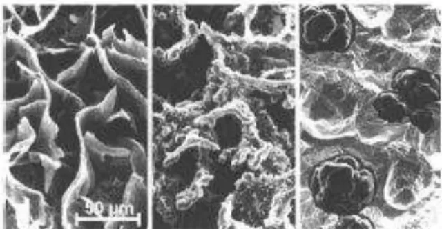
constructions, especially automotive engine blocks, because of its mechanical and thermal properties. Grey cast iron, compacted graphite iron and ductile iron differ in terms of the shape of the graphite particles (Fig. 1). Grey iron is characterized by randomly oriented graphite flakes, while the graphite particles in ductile iron are individual spheres. In contrast, the graphite particles in compacted graphite iron are vermicular particles. These particles are elongated and randomly oriented as in grey iron; however, they are shorter and thicker and have round edges (Abele et al., 2002).
With microstructural and mechanical characteristics among those of grey and ductile iron, CGI is stronger and stiffer than grey iron while having better castability, machinability and thermal conductivity than ductile irons. The properties of CGI lend
Paper accepted July, 2010. Technical Editor: Anselmo E. Diniz
themselves to use in components that undergo both mechanical and thermal loading (Dawson et al., 2001).
Figure 1. Cast iron graphite morphology (left: grey cast iron, middle: compacted graphite iron, right: ductile iron) (Abele et al., 2002).
The reason why CGI has not been used to date in large-scale production in the automotive industry is its lower machinability when compared to grey cast iron, especially at high cutting speeds, which are mandatory for large-scale automotive production lines. Also, in continuous cutting processes, like cylinder-boring operations, the tool life decreases dramatically when grey cast iron is replaced with CGI (Heck et al., 2007). This is due to the greater tensile strength and stiffness of CGI compared to grey iron, and the pearlitic CGI structure (Skvarenina and Shin, 2006).
of conventional grey cast iron and hence the formation of MnS-inclusions does not occur (Abele et al., 2002; Heck et al., 2008).
One of the largest cylinder block machining operations, in terms of real time cutting, is drilling using helical flute drills. Although drilling is one of the oldest and most widely used of all machining operations, it is also one of the most complex processes. The conventional twist drill is very complex in shape, and the characteristic that distinguishes drilling from other machining operations is the combined cutting and extrusion of metal at the chisel edge in the centre of the drill.
The cutting action along the lips of the drill is not unlike that in other machining processes. Due to variable rake angle and inclination, however, there are differences in the cutting action at various radii on the cutting edges. This is complicated by the constraint of the whole chip on the chip flow at any single point along the lip, and the velocity of the cutting lips is not consistent as with many other cutting processes, but varies along the cutting lips (SME, 1983; Wen-Chou et al., 1996).
In order to achieve better results during a drilling operation, this process is often improved with the application of cutting fluids, like other machining processes. Although coolants are rather difficult to apply to the cutting edges in drilling, these fluids change the tribological processes, which occur when two surfaces – tool and workpiece – make contact. Cutting fluids normally increase the tool lifetime and process performance, reducing the roughness values (Andrade, 2005: Sreejith, 2008).
Different kinds of additives are used to improve the performance and longevity of lubricants. Depending on the specific demands and performance level requirements, several different classes of additives may be used. These include detergents, dispersants, extreme pressure (EP), antiwear (AW), viscosity index improvers (VIIs) and corrosion inhibitors (Waara et al., 2001).
In metalworking operations hydrodynamic and boundary (or extreme pressure, EP) lubrication conditions can exist. In hydrodynamic lubrication, a film of fluid or lubricant always separates the moving surfaces. Under boundary lubrication conditions, the two surfaces rub against each other and wear results. Under conditions of very severe wear, nascent metal surfaces can be produced. The EP additives in cutting fluid are organic or inorganic compounds that contain phosphorus, chlorine, sulphur, copper or other elements. These additives react with the metal surfaces forming a tribofilm that affects friction and wear, e.g., iron sulphide or metallic copper (Pawlak et al., 2005).
For industrial applications it is of great interest to understand which effects different cutting fluids additives have on the workpiece surface, because it is well known that adsorption and reaction layers of machining processes hinder thermochemical heat treatment. Soft spots, thin nitride layers and other defects can be generated by adsorption and reaction layers on the machined metal surface (Brinksmeier et al., 2004).
This paper aims to evaluate the influence of EP additives on the drilling process of CGI. Cutting fluids with and without EP additives were used. The tool wear was observed in order to investigate the need for an EP additive in the cutting fluid for this machining process.
Protective Layers and EP Additives
The use of EP (extreme pressure) additives leads to the formation of protective layers upon high loading in the friction process. These additives consist of chlorine, sulphuric, and phosphoric compounds which react tribochemically with the metal surface during the mechanical interaction and develop a well-adhered and easy-to-shear protective layer (Heinicke, 1984).
Reaction between the metallic surface and the additive may also reduce adhesion. At the points of contact between the surfaces where the temperature is high, the additive prevents the formation of an adhesion bridge by reacting with the metallic surface (Iliuc, 1980).
In order to prevent the appearance of larger metal-metal contact regions and thereby wear, the formation of a new layer by reaction of the EP additives with the friction area has to follow the layer destruction before further mechanical stress takes place. Therefore, the additive has to react with the metal with sufficiently high velocity (Heinicke, 1984).
The action of EP proceeds through some (but not necessarily all) of the following steps (Schey, 1984):
1) Interactions between the additives and the environment (oxygen, water, other additives, and carrier fluid) produce more reactive species.
2) The additive and/or the reactive species adsorbs onto the metal surface.
3) Under the intense contact pressure and temperature further reactive species may be formed, and bonded in the active molecule to form polymeric films. These usually show an increased concentration of the active element in the form of organic or organometallic compounds, often together with oxides. Remaining organic radicals enter the bulk lubricant and may contribute to the reactions described in step 1.
4) The reaction product is worn away by sliding, and also by chemical dissolution and is either lost on the exiting workpiece or re-enters the bulk lubricant, changing its rheology and reactivity.
5) The reaction product is re-established by steps 1 to 3 above. Successful lubrication depends on maintaining a balance between the removal and regeneration of the reaction product.
6) Adsorption also plays an important role in the development of this reaction, because prior to reaction the additive is adsorbed on the surface. If the additive is more readily adsorbed, the higher is its concentration on the surface and the greater is its reaction rate (Iliuc, 1980).
Such layers can form in the following fundamental ways (Heinicke, 1984):
I. Spontaneous formation of layers from the reactants:
Fe
FeX
R
RX
(1)II. Formation of layers via the formation of sorption stages:
Fe
X
R
Fe
RX
...
(2)
FeX
R
Fe
RX
...
(3)III. Formation of layers following the preceding
decomposition or reformation of the additives:
X
R
RX
,RX
R
'
X
R
''
(4)FeX
Fe
X
,R
'
X
Fe
FeX
R
'
(5)where:
Fe: iron
X: elements such as phosphorus and sulphur present in the fluids R: fluid base
additives containing S, Cl or P, a spontaneous formation of layers was detected upon impact with the metal surface, accompanied by the formation of iron compounds and residual products. Iron phosphate and iron sulphides are important reaction products in reactions with phosphorus and sulphur-containing additives, respectively.
According to Braun (2007), the mechanism of sulphur carriers under EP conditions can be described as beginning with physical adsorption followed by chemisorption and finally cleavage of the sulphur and its reaction with the metal surface (Fig. 2). Generally, this reaction takes place at temperatures over 600C.
Figure 2. Mechanism of sulphur carriers under extreme pressure conditions (Braun, 2007).
According to Brinksmeier and Walter (2000) researches have shown that sorption and reaction layers can influence the chip formation positively and lead to reduced surface roughness and friction forces.
Generally, several processes contribute to the formation of a protective layer, e.g. the development of oxide, polymeric and other reaction layers. In this way, protective layers may be produced with an appropriate combination, which remain constant and do not lose their lubricating effect even with the deformation of the basic metal.
In summary, it may be concluded that tribochemical reactions play important roles in the formation of anti-frictional and anti-wear protective layers. Also, tribochemical reactions lead to changes in the properties of the surface layer. A potential for decreasing tool wear exists if a reaction layer forms and prevents contact between the cutting tool and the workpiece.
Methodology
Drilling tests
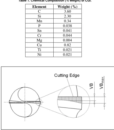
The experiments were carried out in a very rigid CNC machining centre with 7.64 kW of power and maximum rotation of 5000 rpm. The tested twist drills were solid cemented carbide (ISO K40 grade, point angle of 140) coated with a TiNAl layer, each with a diameter of 10 mm. The workpieces were compacted graphite iron plates with the chemical composition shown in Table 1. The workpiece dimensions were 400 mm x 300 mm x 45 mm and average hardness was 213 HB. The electrical power consumed by the main motor of the machine was measured during the drilling operation.
In order to ensure comparability between the different cutting fluid types, a common set of cutting parameters was used for all the tests. A cutting speed of 110 m/min and a feed speed of 350 mm/min were used. The depth of the holes was 20 mm.
After drilling 5 holes on the workpiece, the flank wear (VB) of the drilling tool was measured using a tool microscope. The position of the flank wear measurement is shown in Fig. 3. This procedure was adopted until the wear reached the end-of-life criteria (VBBmax = 0.3 mm).
Table 1. Chemical Composition (% weight) of CGI.
Element Weight (%)
C 3.60
Si 2.30
Mn 0.34
P 0.038
Sn 0.041
Cr 0.044
Mg 0.004
Cu 0.82
Ti 0.021
Ni 0.021
Figure 3. Flank wear measurement of drill tools.
The cutting fluids used in the drilling tests are described in Table 2. Different base oil and EP additive concentrations were evaluated in the selection of the cutting fluid for this study. All cutting fluids were semi-synthetic fluids. Also, in Table 2, the % is expressed in weight of base oil and additive in each cutting fluid formula.
Table 2. Description of cutting fluids used in drilling tests.
Type of cutting fluid
Base oil Additives Density
(g/cm3)
pH
Type A Mineral oil
(35%) + ester (10%)
EP additive (10%)
0.978 9.0/9.5
Type B Mineral oil
(50%)
EP additive (5%)
1. 020 8.8-9.2
Type C Polymer
(20%)
No EP additive
1.011 9.0-9.4
SEM/EDS surface analysis
After the drilling tests, the tools were rinsed with acetone prior to surface analysis. The worn drill surface was analyzed with a Scanning Electron Microscope/ Electron Detector System (SEM/EDS) to obtain an indication of the elements present in the surface films formed during the cutting process.
Results and Discussion
Tool life
length machined, the wear behaviour was similar for all cooling conditions studied, but above this length for dry drilling and cutting fluid C the wear increased faster than under the other conditions (cutting fluid A and B). Less wear was observed for drilling with cutting fluid A. Probably, the better performance of cutting fluids A and B is due to the presence of EP additive in the cutting fluid formula. Also, Aronson (1994) reported that better results are obtained when cutting fluids are used in the drilling process.
SEM images were used to characterize the tool wear. As can be observed in Fig. 5 (end of tool life), the results of the tests indicated that abrasion and adhesion were the main wear mechanisms in CGI drilling. Image D (Fig. 5(d)) shows that there is metal adhered to the boundary of the main cutting edge under dry conditions. Abrasive wear is normally the major wear mechanism of tools when cutting fluids are used. The SEM images of the worn flank surface of the tool are shown in Fig. 5(a, b and c). The worn surface, as shown in Fig. 5(a), has deeper scratches and cracks on the flank face of the drilled tool. According to Abele et al. (2002) abrasive and adhesive wear is verified during CGI machining. Also, Xavier (2009) considers abrasive and adhesive wear as the most important wear mechanisms in CGI machining.
Figure 4. Tool flank wear for different cooling conditions.
(a) (b)
(c) (d)
Tribochemical Analysis
In order to evaluate the effectiveness of the EP additive, the EDS results were analyzed. This indicates the elements present on the surfaces, showing whether the film was formed during the CGI drilling process. Figure 6 shows the tool surface composition after dry drilling. The spectrum for the tool surface indicates the presence of primarily Fe (iron), a lesser amount of C (carbon), and a small amount of Ti (Titanium) (coating elements). Thus, it can be concluded that the workpiece material was adhered to the tool surface.
Figure 6. EDS spectra of tool surface after end of life for dry conditions.
Therefore, when cutting fluid is used during the drilling process it is possible to reduce the material adhesion onto tool surface and to improve the tool life. The spectrum shown in Fig. 7 corresponds to the drilling process where a polymeric-based cutting fluid without EP additive was used. Through the spectra analyzed it is possible to verify the presence of W and C, cemented carbide substrate from the drill, and Ti, indicating that the coating (TiAlN) was maintained. The improved tribological process could be explained by the high cooling and lubricant ability of the cutting fluid used. These properties decrease the temperature and friction and, consequently, the tool wear.
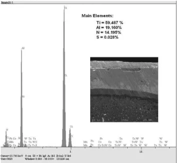
The influence of the sulphur EP additive on the drilling of CGI can be observed in Figs. 8 and 9. EDS analysis indicates the presence of coating elements (Ti and Al) and also sulphur (S) on the tool surface. According to Evans et al. (2007), sulphur EP additives react with steel surfaces to produce sacrificial wear layers that are created and removed with asperity contact during the break-in phase of the test. This explains the presence of S on the tool surface. Also, these results suggest that EP additives react with exposed steel surfaces and together with the transferred coating material form a new tribofilm responsible for improved frictional and wear behaviour (Brinksmeier and Walter, 2000). The improvement in the wear behaviour can be verified in Fig. 4. Also, the active elements in extreme pressure lubricants operate in a similar manner to oxygen; however, they are much more effective (Trent and Wright, 2000).
Figure 7. EDS spectra of tool surface after end of life for the use of cutting fluid C.
Figure 8. EDS spectra of tool surface after end of life for drilling with cutting fluid B.
Figure 9. EDS spectra of tool surface after end of life for drilling with cutting fluid A.
The adhesion process is reduced at the metal-tool interface during the test probably due to the presence of the EP additive in the cutting fluid. Reaction between the metallic surface and the additive may also reduce adhesion at the points of contact. The additive prevents the formation of an adhesion bridge by reacting with the metallic surface (Alves and Oliveira, 2008). This is very important with regard to CGI machining, because the adhesive behaviour is 15% greater for CGI than for grey cast iron.
The use of sulphur-based EP additives gives a faster response in terms of low friction and greater improvement in friction and wear (Alves and Oliveira, 2008).
Conclusions
Based on these experimental results, the following conclusions can be drawn:
The results identified the cutting fluid as a significant factor in the wear reduction during CGI drilling with cemented carbide twist drills coated with TiNAl. On comparing the different conditions of lubrication, dry and with cutting fluid, it is clear that it is possible to increase the tool life by 100% when cutting fluid A is used. Also, the presence of material adhered to the tool surface was verified for dry drilling. Abrasion is the main wear mechanism when a cutting fluid is used.
The tribological behaviour of the drilling process of CGI changes when a cutting fluid is used in the process. The base oil and EP additive are the key factors in achieving good performance. The EDS spectra suggest that sulphur (EP additive) reacts with the metal forming a layer which improves the friction and wear behaviour. Also, the EP additive hinders the formation of an adhered layer by reacting with the metallic surface.
The results obtained show that the main cutting fluid characteristics necessary to improve the drilling performance of CGI are lubricity and an EP support. Thus, on selecting the cutting fluid the base oil and EP additive should be considered. The best combination in this study was given by cutting fluid A: 35% mineral oil, 10% ester and 10% EP additive.
Acknowledgements
The authors would like to thank Castrol Lubricants and Tupy Foundry for the support of this study.
References
Abele, E., Sahm, A., Schulz, H., 2002, “Wear mechanism when machining compacted graphite iron”, Annals of CIRP 2002, Manufactory Technology, 51(1), pp. 53-56.
Alves, S.M., Oliveira, J.F.G., Klocke, F., Maier, B., 2008, “Effects of Sulphur Additive EP in Ester Coolants during Friction with CBN”, Tribology Transactions, Vol. 51, pp. 278-284.
Andrade, C.L.F., 2005, “Drilling in Compacted Graphite Iron”, Master (Thesis), Federal University of Santa Catarina, Florianópolis, Brazil, 154 p. (In Portuguese)
Aronson, R.B., 1994, “Machine Tool 101: Part 6, Machine Servers”. Manufacturing Engineering, June, pp. 47-52.
Braun, J., 2007, “Additives”, In: Mang, T. and Dresel, W., “Lubricants and Lubrication”, Germany, WILEY-VCH, pp. 88-118.
Brinskmeier, E., Walter, A., 2000, “Generation of Reaction Layers on Machined Surfaces”, CIRP Annals – Manufacturing Technology, Vol. 49(1), pp. 435-438.
Brinksmeier, E., Lucca, D.A., Walter, A., 2004, “Chemical Aspects of Machining Processes”, CIRP Annals – Manufacturing Technology, Vol. 53(2), pp. 685-699.
Dawson, S. et al., 2001, “The effect of metallurgical variables on the machinability of compact graphite iron”, SAE Technical Paper Series, 2001-01-0409.
Dawson, S., 2002, “Compacted graphite iron: mechanical and physical properties for engine design”, SinterCast Technical Publication, Stockholm, Sweden.
Evans, R.D., Nixon, H.P., Darragh, C.V., Howe, J.Y., Coffey, D.W., 2007, “Effects of extreme pressure additive chemistry on rolling element bearing surface durability”, Tribology International, Vol. 40, pp. 1649-1654.
Heck, M., Ortner, H.M., Flege, S., Reuter, U., Einsinger, W., 2008, “Analytical investigations concerning the wear behaviour of cutting tools used for the machining of compacted graphite iron and grey cast iron”, International Journal of Refractory Metal and Hard Materials, Vol. 26(3), pp. 197-206.
Heinicke, G. in co-operation: Hennig, H.L. et al., 1984, Tribochemistry. Carl Hanser Verlag, München.
Iliuc, I., 1980, “Tribology of Thin Layers”, Tribology Series, 4, Elsevier Scientific Company.
Pawlak, Z., Klamecki, B.E., Rauckyte, T. ,Shpenkov, G.P., Kopkowski, A., 2005, “The tribochemical and micellar aspects of cutting fluids”, Tribology International, Vol. 38, pp. 1-4.
Schey, J.A., 1984, “Tribology in Metalworking: Friction, Lubrication and Wear”, Ed. American Society for Metals.
Skvarenina, S., Shin, Y.C., 2006, “Laser-assisted machining of compacted graphite iron”, International Journal of Machine Tools & Manufacture, Vol. 46, pp. 7-17.
Sreejith, P.S., 2008, “Machining of 6061 aluminium alloy with MQL, dry and flooded lubricant conditions”, Materials Letters, Vol. 62, pp. 276-278.
SME (Society of Manufacturing Engineers), 1983, Tool and Manufacturing Engineers Handbook – Machining, 4. Edition. Dearborn, One S.M.E. Drive, Vol. 1.
Trent, E.M. and Wright, P.K., 2000, Metal Cutting, 4th edition, Butterworth-Heinemann, United States of America.
Xavier, F.A., 2009, “Study of Wear Mechanisms in Si3N4 Tool Applied
in Machining of Compacted Graphite and Grey Cast”, Doctoral Thesis, Federal University of Santa Catarina, Florianópolis, Brazil, 308 p. (In Portuguese)
Waara, P., Hannu, J., Norrby, T., Byheden, A., 2001, “Additive influence on wear and friction performance of environmentally adapted lubricants”, Tribology International, Vol. 34, pp. 547-556.