Abs tract
Optimisation of stacking sequence for composite panels under slamming impact loads using a genetic algorithm method is stud-ied in this paper. For this purpose, slamming load is assumed to have a uniform distribution with a triangular-pulse type of inten-sity function. In order to perform optimisation based on a genetic algorithm, a special code is written in MATLAB software envi-ronment. The optimiser is coupled with the commercial software ANSYS in order to analyse the composite panel under study and calculate the central deflection. After validation, different cases of stacking sequence optimisation are investigated for a variety of composite panels. The investigations include symmetric as well as asymmetric conditions of stacking sequence. Results obtained from these analyses reveal the fact that the adopted approach based on a genetic algorithm is highly capable of performing such optimisa-tions.
Key words
Composite Panel; Stacking Sequence; Slamming Impact Load; Optimisation; Genetic Algorithm (GA); Finite Element Analysis (FEA)
Stacking Sequence Optimisation of Composite Panels
Subjected to Slamming Impact Loads using a Genetic
Algorithm
1 INTRODUCTION
Composite materials owing to their lower densities and also higher strength-to-weight ratios are considered to be more advantageous than metallic materials. Besides, composite structures exhibit good resistance against alternate loads, climate effects and especially degradation effects of corro-sion. On the other hand, composites are purely non-magnetic materials. All of these properties and characteristics make it reasonable to imagine wide applications for the composite materials in the marine industries. Of course, some of the characteristics of composite materials put different limita-tions on the way of their applicalimita-tions in real practice. Among such disadvantages or weaknesses, reference may be made to their lower modulus of elasticity and also lower fire resistance. Due to the limitations on the modulus of elasticity for the composite materials, they can not be applied in the construction of long vessels. In spite of all discussed matters, the range of applications of composite
Mo ham m ad Re za Kh e dm ati*, a, Mo ham m ad Re za i Sa ng tab ib, Me h di Fa koo rib
aAssociate Professor, Faculty of Marine
Tech-nology, Amirkabir University of TechTech-nology, 424 Hafez Avenue, Tehran 15914, Iran
bMSc Graduate of Ship Structures Engineering,
Faculty of Marine Technology, Amirkabir Univer-sity of Technology, 424 Hafez Avenue, Tehran 15914, Iran
Received 05 Aug 2012 In revised form 13 Mar 2013
Latin American Journal of Solids and Structures 10(2013) 1043 – 1060
materials in the construction of high speed marine vehicles is outstanding. In other words, one cate-gory of the main structural materials for building high speed crafts is devoted to the composite materials.
Composite panels in the structure of high speed crafts are typically subjected to many different types of in-plane or out-of-plane loads. Among these loads, slamming impact loads are to be consid-ered with a high level of attention. The high speed crafts operate among unsteady sea waves and due to the interactions existing between the crafts and the sea waves, the structural panels of the crafts have to sustain lateral impact loading induced by slamming phenomenon.
It should be noted that the problem of composite panels subjected to lateral impact loads has at-tracted the attention of many researchers. Of course, most of the research studies are devoted to the structural response analysis of the composite panels under impact by a spherical impactor.
Von Karman [1] was one of the first researchers who investigated the hydrodynamic impact problem by studying seaplane floats during landing. He introduced the concept of added mass due to the water motion induced by the body. This work was followed later by Wagner [2] who consid-ered piled-up water effects. The body was modelled as a flat plate, whose width is determined by the intersection between the elevation of the free surface and the body position. The resulting force is obtained by integrating the pressure distribution. Wagner’s work was truly remarkable so that it is still being used in order to estimate the lateral impact loads. In both of these methods, the hydro elasticity effects induced by fluid-structure interactions were ignored. Figure 1 represents a schemat-ic view on the pressure distribution at the event of slamming.
Figure 1 A schematic representation of slamming impact pressure distribution.
It should be emphasised that the slamming is an impulsive time-depending phenomenon in which the pressure distribution changes over the period of time. One interesting model in order to investigate the slamming phenomenon is the one developed by Qin and Batra [3] in which the hy-dro elasticity effects were also included. As a summary, it can be said that there are numerous models for description of slamming impact load distribution, each of which is based on some as-sumptions. Depending on the relevant assumptions, any of the models can approximate the slam-ming load distribution with a corresponding level of accuracy.
ener-Latin American Journal of Solids and Structures 10(2013) 1043 – 1060 gy absorption. Damage resistance is a property that enables a structure to resist the onset of dam-age. Damage tolerance enables a structure to resist the effects of damdam-age. The goal in energy-absorbing designs is to dissipate as much of the kinetic energy as possible.
Genetic algorithms (GAs) are search techniques based on natural selection and population genet-ics. Selection, crossover and occasionally mutation are applied to a population of candidate solutions sampled from the larger design space, with fitter individuals having a higher probability of repro-ducing. Genes that predispose certain individuals to have improved fitness are thus sampled more frequently and propagated throughout the population. GAs are robust optimisers that can handle real/discrete variables [4]. Detailed treatments of this ever-growing field may be found in textbooks [5-7].
Callahan and Weeks [8] studied the optimisation of composite laminates using genetic algo-rithms. Genetic algorithms are nowadays considered as a powerful tool for optimisation of compo-site panels. Common variables included in such optimisation problems are typically structural di-mensions, stacking method, ply materials, ply thicknesses and ply angles. Rahul and Dutta [9] adopted genetic algorithms in order to optimise weight and cost of fibre reinforced composites against impact loads.
Optimisation of stacking sequence for composite panels under slamming impact loads using a genetic algorithm method is studied in this paper. In order to perform optimisation based on a ge-netic algorithm, a special code is written in MATLAB software environment. The optimiser is cou-pled with the commercial software ANSYS in an especial procedure that in each optimisation step analyses the composite panel under study and calculates the central deflection. The coupled GA-FEA procedure is validated against some available data. Different cases of stacking sequence opti-misation are investigated for a variety of composite panels. The investigations include symmetric as well as asymmetric conditions of stacking sequence.
2 FINITE ELEMENT ANALYSIS
2.1 Finite element code and adopted elements for discretisation
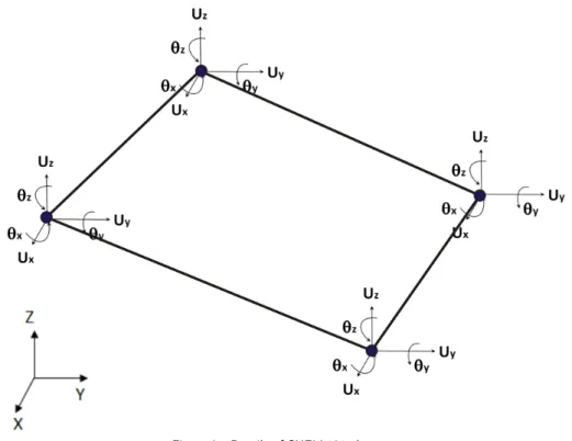
In order to determine the type of finite element analysis of the composite panels studied here, it should be noted that the lateral loads are impulsive and of rapidly varying nature. Therefore, all finite element analyses are to be of transient dynamic type. Besides, large geometric deflections are to be accounted for in the analyses. All of the finite element analyses in this study are carried out using the commercial code ANSYS [10]. SHELL181 elements are selected in order to discretise the composite panels, Fig. 2. These elements have four nodes and six degrees of freedom per node. The formulation of SHELL181 elements is based on first order deformation theory. The reasons behind adopting such elements for finite element analyses in this study include high accuracy of results together with low CPU time.
Latin American Journal of Solids and Structures 10(2013) 1043 – 1060
Figure 2 Details of SHELL181 element.
2.2 Validation of geometrically non-linear transient dynamic analysis procedure
In order to check the validity of the procedure established in the ANSYS code for performing geo-metrically non-linear transient dynamic analyses, the model investigated by Kazanc and Mecitoglu [11] is studied here. Kazanc and Mecitoglu studied the nonlinear dynamic response of simply sup-ported laminated composite plates subjected to blast loading. Such a kind of loading is similar in nature to the slamming impact load; both are of rapidly varying type. Kazanc and Mecitoglu de-rived the governing dynamic equations for the composite plate using the virtual work principle. They applied von Karman large deflection theory in order to consider the geometrical non-linear effects. They also adopted the Friedlander exponential decay equation [12] as follows for describing the distribution of blast load
P
(
t
)
=
P
m(1
−
t
/
t
p)
e
−αt/tp(1)
Latin American Journal of Solids and Structures 10(2013) 1043 – 1060 Table 1 Geometrical specifications, material and loading properties of the model adopted for validation
Figure 3 Comparison of present numerical results with those of other researchers.
Geometry of panel
[0/90/0] Panel lay-up (Cross ply)
2.54 Length of panel (m)
2.54 Width of panel (m)
0.17 Thickness of panel (m)
Mechanical properties of material
132.4 Longitudinal modulus, E1 (GPa)
10.8 Transverse modulus, E2 (GPa)
5.6 Shear Modulus, G12 (GPa)
0.24 Poisson Ratio,
υ
12
1443 Density,
ρ
(Kg/m3)Load parameters
3447 Maximum load,
P
m(KPa)0.1
t
p (Sec)2
Latin American Journal of Solids and Structures 10(2013) 1043 – 1060
2.3 Dynamic response of a composite panel subjected to slamming impact load
In this section, the dynamic response of a composite panel under slamming impact load is studied. Table 2 represents the geometry of the panel and relevant mechanical properties which are taken from Aslan et al. [14]. The material of the panel is of E-glass/Epoxy type considering its maritime applications.
Table 2 Geometrical specifications and material properties of the composite panel adopted for optimization studies
Geometry of panel
[0/90/0/90] Panel lay-up
1 Length of panel (m)
0.5, 1.0, 1.5 Width of panel (m)
8 Thickness of panel (mm)
Mechanical properties of material
44 Longitudinal modulus, E1 (GPa)
10.5 Transverse modulus, E2 (GPa)
5.6 Shear Modulus, G12 (GPa)
0.24 Poisson Ratio,
υ
121443 Density,
ρ
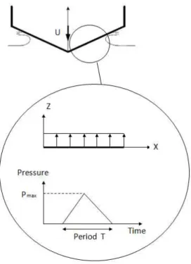
(Kg/m3)Slamming impact load is distributed all over the surface of the panel and its intensity changes in time according to a triangular pulse diagram as indicated in the Fig. 4. The pulse pressure parame-ters are taken as P
max=100KPa and T =50ms. The composite panel is simply supported along its boundaries. Dynamic response of the panel subjected to slamming impact load is shown in the Fig. 5. As can be seen in the Fig. 5, the maximum value of central deflection in the panel is equal to
5.6cm that is obtained at a certain time, which is equal to the half of the loading time period. In order to investigate the response of the composite panel after the loading time period, or after slamming load vanishes, the diagram is extended until t=80ms. It can be realised that even after
Latin American Journal of Solids and Structures 10(2013) 1043 – 1060 Figure 4 Modelling scheme for slamming impact load.
Latin American Journal of Solids and Structures 10(2013) 1043 – 1060
3 OPTIMISATION PROCEDURE USING A GENETIC ALGORITHM
3.1 Basic concepts and definitions in genetic algorithms
In the 1950s and 1960s, several computer scientists independently studied the organizations of evo-lutionary systems. Their main idea was to check if such evoevo-lutionary systems could be applied in the simulation of optimisation problems in real engineering practice. The evolutionary systems were of different types, some had population-based schemes for selection and variation, and some others, like many GAs, had binary strings as abstractions of biological chromosomes. Genetic algorithms are developed by applying the principal of survival of the fittest into a numerical search method [6]. They are used as function optimisers particularly when the variables have discrete values. They achieve this by first selecting an initial population where each individual is constructed by bringing together the total number of variables in a binary or other coded form [6]. These individuals are called artificial chromosomes and they have a finite length string. Every character in the string is an artificial gene, which in the case of binary code has a value of either 1 or 0. The binary code for each design variable represents the sequence number of this variable in the discrete set.
A genetic algorithm initiates the search for finding the optimum in a discrete space by first se-lecting the number of individuals randomly and colse-lecting them together to constitute the initial population. It then makes use of four operators to generate a new population. These operators are selection, mating, crossover and mutation. The detailed explanation of these operators is given in Refs. [6, 15, 16]. Among these, the crossover operator is probably the one which plays an important role in the production of the new generation. There are several types of crossover operators such as single point, two-point, multi-point, uniform and variable crossover. It is shown in Ref. [17] that two-point crossover performs much better among the multi-point crossover techniques. The detailed study carried out on the evaluation of crossover techniques has shown that direct design variable exchange produced the best solutions in the test problems considered [18]. Further, operators such as niche and cloning are suggested in Ref. [19].
3.2 Implementation of a genetic algorithm
Latin American Journal of Solids and Structures 10(2013) 1043 – 1060 which coupling of the finite element approach with the genetic algorithms were demonstrated for optimisation of composite structures.
The main aim of optimisation process in the present study is to minimise the central deflection of a composite panel subjected to slamming impact load. It is obvious that simple analytical expres-sions can not be applied in order to evaluate the fitness of the solutions. Thus, advanced numerical methods are implemented in the optimisation algorithm.
Figure 6 shows the flowchart of the optimisation process based on a genetic algorithm and ap-plying finite element method. The optimisation process consists of two major sections. The first section is devoted to a genetic algorithm. A special genetic algorithm is programmed in the MATLAB environment. Initial population is entered to the genetic algorithm code in the form of random binary strings. The programmed genetic algorithm code has the ability of making changes in the number of chromosomes of the initial population. The governing convergence criterion or stopping condition in the adopted genetic algorithm is assumed as the condition in which the num-ber of generations of the population reaches a certain limit. The value of this limit can be changed depending on the extent of the search space. The so-called roulette wheel method is used in order to perform the function of selection operator in the algorithm. A special capability is considered for the adopted genetic algorithm to be able to use two different crossover operators in an entirely user-defined manner. When the length of chromosomes is relatively short, then the single-point crossover is used as the operator of generation process. This is while; in case of relatively longer chromosomes, three-point crossover is chosen as the operator of generation process.
Latin American Journal of Solids and Structures 10(2013) 1043 – 1060
The second section of the optimisation algorithm is devoted to the application of the finite ele-ment method in order to control the fitness of chromosomes in the population of each of the genera-tions. In order to perform finite element analyses, ANSYS software [10] is used. The intensity func-tion and distribufunc-tion of the slamming impact load are assumed the same as what considered in the Section 2.3. However, it should be emphasized that any other more detailed intensity function and distribution of slamming impact load can be easily implemented in the FEA.
The fitness evaluation process includes three steps. At first, coded chromosomes are decoded so that their relevant stacking sequences become clear. Then, geometrically non-linear finite element analysis is performed on the composite panel for the corresponding stacking sequence. For this pur-pose, both genetic algorithm code and finite element code are coupled in an especial procedure with each other. Finally, fitness of the chromosomes is to be evaluated. As explained earlier, the object of the present optimisation process is set to the minimisation of central deflection of the panel under lateral slamming impact load. Thus, the stacking sequence of plies that leads to a minimum deflec-tion shows a maximum fitness. In order to determine the fitness of chromosomes, the following rela-tionship is evaluated
Fitness value
(ch)=
C
−
Disp
.
(ch) (2)The quantity Disp. in Eq. 2 represents the value of central deflection of the composite panel that is obtained from finite element analyses. The superscript (ch) in Eq. 2 also means that the
corresponding values change for each chromosome. The parameter
C
has a constant valuethroughout any time using of the optimisation process. In other words, the value of parameter
C
isunchanged for all chromosomes in all generations. Based on above statements, for selection operator and also when evaluating the fitness function for chromosomes, the Eq. 1 is used. On the other hand, in order to show how the fitness function promotes along succeeding generations in the GA, the values of central deflection are represented as the fitness. The reason behind this is to show in a better way the process of minimisation of central deflection for the composite panel.
4 APPLICATION EXAMPLES
Different cases are investigated below in order to show how the optimum stacking sequence of the plies is determined for the slamming impact loaded composite panels applying the adopted GA-FEA optimisation procedure. The cases include both symmetric and asymmetric stacking sequences for the composite panels having different numbers of plies.
4.1 Optimum stacking sequences for symmetric four-ply composite panels
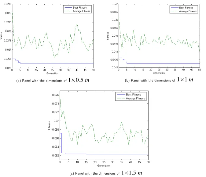
In optimisation of symmetric four-ply composite panels under slamming loads, stacking sequence is assumed in the form of [α/β/β/α]. Optimisation subject is studied for three different dimensions of the panel; 1×0.5m, 1×1m and 1×1.5m. An important matter that exists in solving such a
Latin American Journal of Solids and Structures 10(2013) 1043 – 1060 generations. The parameters adopted are single-point crossover, mutation rate equal to 0.1 and crossover rate equal to 0.8. Fitness function evaluation in the GA for symmetric four-ply composite panels with different dimensions is shown in Fig. 7. As can be seen in the Fig. 7, with taking a rela-tively wide range of generations, it is assured that global optimum points inside the search spaces are reachable. However, this wide range of generations leads to a greater CPU time in the process of optimisation.
(a) Panel with the dimensions of
1
×
0.5
m
(b) Panel with the dimensions of1
×
1
m
(c) Panel with the dimensions of
1
×
1.5
m
Figure 7 Fitness function evolution in the GA for symmetric four-ply composite panels.
Latin American Journal of Solids and Structures 10(2013) 1043 – 1060
condition and also loading condition of the panel are all symmetric in such a case, it is realised that balanced lay-ups have been obtained for the panel. This is another fact confirming the validity of adopted GA-FEA procedure.
Table 3 Comparison of optimum stacking sequences for symmetric four-ply composite panels
Minimum Deflection (m) Optimum Lay-up
Panel Dimension
0.0252 [−45 / 20 / 20 /−45]
[ 45 /
−
20 /
−
20 / 45]
1
×
0.5
m
0.0437 [45 /−45 /−45 / 45]
[−45 / 45 / 45 /−45]
1
×
1
m
0.0623
[
−
45 / 60 / 60 /
−
45]
[45 /
−
60 /
−
60 / 45]
1
×
1.5
m
4.2 Optimum stacking sequences for asymmetric four-ply composite panels
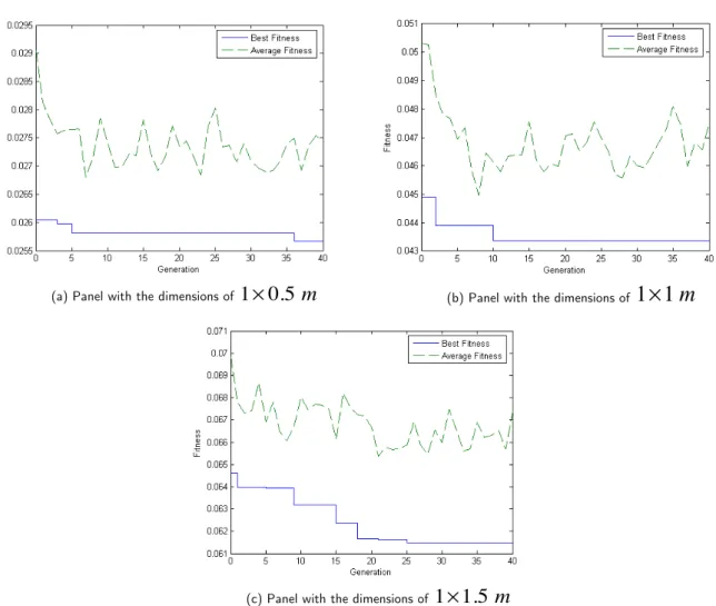
In this section, optimisation process is performed on the same panels investigated in previous sec-tion, but having asymmetric stacking sequences where the angles of plies are [α /β/γ /λ]. For such a problem, it is certainly obvious that the search space is wide. Therefore, three-point crossover is implemented. During optimisation procedure, 40 generations of population are produced. The number of chromosomes in the initial population is increased from 12 to 20. Mutation and crossover rates are considered to be equal to 0.1 and 0.8, respectively. Evaluation of fitness function in the GA for asymmetric four-ply composite panels with different dimensions is shown in Fig. 8. Also, a comparison of optimum stacking sequences for asymmetric four-ply composite panels is provided in Table 4.
Table 4 Comparison of optimum stacking sequences for asymmetric four-ply composite panels
Minimum Deflection (m) Optimum Lay-up
Panel Dimension
0.0255 [−80 / 45 /−10 / 90 ]
[80 /−45 / 10 /−90 ]
m
5
.
0
1
×
0.0433[−45 / 45 /−45 / 45]
[ 45 /−45 / 45 /−45]
m
1
1
×
0.0614
[−45 / 45 / 60 /−60 ]
[ 45 /−45 /−60 / 60 ]
m
Latin American Journal of Solids and Structures 10(2013) 1043 – 1060 (a) Panel with the dimensions of
1
×
0.5
m
(b) Panel with the dimensions of1
×
1
m
(c) Panel with the dimensions of
1
×
1.5
m
Figure 8 Fitness function evolution in the GA for asymmetric four-ply composite panels.
As can be seen from the results in Table 4, for any specific dimension of the composite panel in the case of asymmetric stacking sequence, two optimum lay-ups are obtained using the GA-FEA optimisation process. In both optimum lay-ups, the amount of central deflection is unchanged and furthermore, the angles of plies are same in absolute value but different in the sign. One interesting point that can be realised from comparison of the results reflected in Table 3 and Table 4 is that by changing symmetric stacking sequence to asymmetric one, the amount of central deflection is re-duced by 1 mm for any specific dimension of the panel.
4.3 Optimum stacking sequences for symmetric six-ply composite panels
Optimisation is performed for the symmetric six-ply composite panels. Stacking sequence is of [α /β/γ /γ /β/α] and also the panel has different dimensions of 1×0.5m, 1×1m and 1×1.5m.
Latin American Journal of Solids and Structures 10(2013) 1043 – 1060
operator is applied in this process. Mutation and crossover rates are considered to be equal to 0.1 and 0.8, respectively. Evaluation of fitness function in the GA for symmetric six-ply composite pan-els with different dimensions is shown in Fig. 9. Also, a comparison of optimum stacking sequences for symmetric six-ply composite panels is provided in Table 5.
(a) Panel with the dimensions of
1
×
0.5
m
(b) Panel with the dimensions of1
×
1
m
(c) Panel with the dimensions of
1
×
1.5
m
Figure 9 Fitness function evolution in the GA for symmetric six-ply composite panels.
Comparison of results for symmetric four-ply composite panels in Table 3 with those for sym-metric six-ply composite panels in Table 5 shows that there are some similarities in the optimum stacking sequences for these two cases when the panel has the dimensions of 1×1m or 1×1.5m.
Latin American Journal of Solids and Structures 10(2013) 1043 – 1060 Table 5 Comparison of optimum stacking sequences for symmetric six-ply composite panels
Minimum Deflection (m) Optimum Lay-up
Panel Dimension
0.0253
[−80 / 45 /−10 /−10 / 45 /−80 ] [ 80 /−45 / 10 / 10 /−45 / 80 ]
m
5
.
0
1
×
0.0434[ 45 /−45 /−45 /−45 /−45 / 45]
[−45 / 45 / 45 / 45 / 45 /−45]
m
1
1
×
0.062 [−45 / 60 / 60 / 60 / 60 /−45 ]
[ 45 /−60 /−60 /−60 /−60 / 45 ]
m
5
.
1
1
×
4.4 Optimum stacking sequences for asymmetric six-ply composite panels
Asymmetric six-ply composite panels are investigated in this section. The lay-up of the panels is assumed in the form of [α/β/γ /λ/η/ζ]. Again, since the search space in this case is very wide comparing with the other previous cases, three-point crossover operator is utilised. Initial popula-tion has 30 chromosomes and optimisapopula-tion process is carried out for 50 generapopula-tions. Mutapopula-tion and crossover rates are considered to be equal to 0.15 and 0.9, respectively. Fitness function promotion in the GA for asymmetric six-ply composite panels with different dimensions is shown in Fig. 10. Also, a comparison of optimum stacking sequences for asymmetric six-ply composite panels is pro-vided in Table 6.
Table 6 Comparison of optimum stacking sequences for asymmetric six-ply composite panels
Minimum Deflection (m) Optimum Lay-up
Panel Dimension
0.0249
[
−
70 / 45 /
−
30 / 10 / 0 /
−
80]
[70 /
−
45 / 30 /
−
10 / 0 / 80]
m
5
.
0
1
×
0.0432 [−45 / 45 / 45 /−45 /−45 / 45][45 /−45 /−45 / 45 / 45 /−45]
m
1
1
×
0.0608
[
−
45 / 45 / 60 /
−
60 /
−
60 / 60]
[ 45 /
−
45 /
−
60 / 60 / 60 /
−
60]
m
Latin American Journal of Solids and Structures 10(2013) 1043 – 1060
(a) Panel with the dimensions of
1
×
0.5
m
(b) Panel with the dimensions of1
×
1
m
(c) Panel with the dimensions of
1
×
1.5
m
Figure 10 Fitness function evolution in the GA for asymmetric six-ply composite panels.
Latin American Journal of Solids and Structures 10(2013) 1043 – 1060 obey the [α /−α/−β/β/γ /−γ] lay-up. So such a proposal on the optimum lay-up in the case of asymmetric six-ply composite panels can not be generalised to different aspect ratios or sizes of the panels.
5 CONCLUSIONS
In this paper, an investigation was made into optimization of stacking sequence for the composite panels under slamming impact loads typically observed in the marine applications. The slamming impact load was considered to be evenly distributed over the panel surface, but varying in a trian-gular pulse manner with time. A genetic algorithm was coupled parallel to the finite element ap-proach in order to solve the optimisation problem. Optimisation was performed for a variety of different cases changing in the panel dimensions as well as the lay-ups. The optimisation process was also validated in some way using the results for the case of a composite panel of dimensions
1×1m with symmetric stacking sequence. Out of the results obtained for various cases, it can be
simply said that when the stacking sequence of the composite panel is asymmetric, then optimum lay-up follows the form of [α /−α/−β/β/γ /−γ]. Of course, there are some exceptions against this lay-up, especially when the aspect ratio of the panel is about 0.5 as in the case of the panel with dimensions of 1×0.5m. For any specific number of plies, optimum asymmetric stacking sequence
leads to a reduction in the central deflection of the panel in comparison with the case of applying optimum symmetric stacking sequence. The amount of reduction changes from case to case.
References
[1] Von Karman T. The impact on a seaplane floats during landing. Technical Notes for National Advisory Com-mittee for Aeronautics, N.A.C.A. TN321, Washington, 1929.
[2] Wagner H. Uber stoss end an der oberfache von Flussigkeiten. Zeitschrift fur Angewandte Mathematik und Mechanik, 1932;12:193–215.
[3] Qin Z, Batra RC. Local slamming impact of sandwich composite hulls. International Journal of Solids and Structures 2009;46(10):2011-2035.
[4] Yong M, Falzon BG, Iannucci L. On the application of genetic algorithms for optimising composites against impact loading. International Journal of Impact Engineering, 2008;35(11):1293-1302.
[5] Holland J. Adaptation in natural and artificial systems. Ann Arbor, University of Michigan Press, 1975.
[6] Goldberg DE. Genetic algorithms in search, optimization and machine learning. Reading, Addison-Wesley, 1989.
[7] Mitchell M. An introduction to genetic algorithms. Cambridge, MIT Press, 1996.
[8] Callahan KJ, Weeks GE. Optimum design of composite laminates using genetic algorithms. Compos Eng, 1992;2(3):149–160.
Latin American Journal of Solids and Structures 10(2013) 1043 – 1060
[10] ANSYS 10.0 Reference Manual, ANSYS Inc.
[11] Kazanc Z, Mecitoglu Z. Nonlinear dynamic behavior of simply supported laminated composite plates subjected to blast load. J. of Sound and vibration, 2008;317(3-5):883-897.
[12] Gupta AD, Gregory FH, Bitting RL, Bhattacharya S. Dynamic analysis of an explosively loaded hinged rec-tangular plate. Computers & Structures, 1987;26(1-2):339–344.
[13] Librescu L, Nosier A. Response of laminated composite flat panels to sonic boom and explosive blast loadings. AIAA Journal, 1990;28(2):345-352.
[14] Aslan Z, and Karakuzu R, Okutan B. The response of laminated composite plates under low-velocity impact loading. Composite Structures, 2003;59(1):119-127.
[15] Leite JPB, Topping BHV. Improved genetic operators for structural engineering optimization. In: Topping BHV, editor. Developments in neural networks and evolutionary computing for civil and structural engineering, Edinburgh, UK, 1995:143-69.
[16] Camp C, Pezesk S, Cao G. Optimized design of two-dimensional structures using a genetic algorithm. Journal of Structural Engineering, ASCE 1998;124(5):551-9.
[17] Chen T-Y, Chen C-J. Improvements of simple genetic algorithm in structural design. International Journal for Numerical Methods in Engineering 1997;40(7):1323-34.
[18] Hasancebi O, Erbatur F. Evaluation of crossover techniques in genetic algorithm based optimum structural design. In: Topping BHV, editor. Advances in engineering computational technology, Edinburgh, UK: CIVIL-COMP Press, 1998:111-123.
[19] Suresh A, Mohammed A. An improved genetic algorithm for optimal design of large trusses. In: Topping BHV, editor. Advances in engineering computational technology, Edinburgh, UK: CIVILCOMP Press, 1998: 97-102.
[20] Muc A, Gurba W. Genetic algorithms and finite element analysis in optimization of composite structures. Composite Structures, 2001;54(2-3):275-281.