ABSTRACT: Multifunctional composites combine structural and other physicochemical properties, with major applications in aeronautical, space, telecommunication, automotive, and medical areas. This research evaluates electromagnetic properties of multifunctional composites based on glass iber woven fabric pre-impregnated with epoxy resin laminated together carbon iber non-woven veil metalized with Ni. In this way, searching for possible application as radar absorbing structures or electromagnetic interference shielding structures. The scattering parameters, in the frequency range of 8.2 to 12.4 GHz, show that the epoxy resin/glass iber prepreg allows the transmission of the electromagnetic waves through its microstructure, independently of the glass iber reinforcement orientation (98% transmission, S
24 = −0.09 dB). However, the carbon iber/Ni veil shows highly relector behavior (91% relection, S
22 = −0.43 dB). Energy dispersive spectroscopy of the veil, before and after nitric acid attacks, conirmed the Ni coating removal from the carbon iber surface. Still, the scattering parameters show relector behavior (77% relection, S
22 = −1.13 dB), attributed to the electrical conductivity of carbon ibers. Multifunctional composites based on glass iber/epoxy/carbon iber/Ni veil laminates were processed by hot compression molding. The scattering parameters show that the laminates do not behave as good radar absorbing structures. Nevertheless, the laminates present promising results for application as light weight and low thickness structural composites with electromagnetic interference shielding effectiveness (91.4% relection for 0.36 mm thickness and 100% for ~ 1.1 mm) for buildings, aircraft, and space components.
KEYWORDS: Composite structures, Microwave absorption, Electromagnetic shielding, Glass iber reinforced plastics, Carbon iber reinforced plastics.
Electromagnetic Properties of
Multifunctional Composites Based on Glass
Fiber Prepreg and Ni/Carbon Fiber Veil
Daniel Consoli Silveira1, Newton Gomes2, Mirabel Cerqueira Rezende2,3, Edson Cocchieri Botelho1
INTRODUCTION
Many technological advances in modern society have been achieved since the introduction of advanced and multifunctional materials and structures (Gibson 2012). he development of new multifunctional materials involves the combination of structural requirements with other properties not related to mechanical strength (Gibson 2010; Silveira 2015). herefore, materials with structural properties may be combined — such as tensile, lexural, shear strength, and fatigue resistance — with non-structural materials possessing active properties, for example, electrical and thermal conductivity, self-healing ability, capability to interact with electromagnetic waves, biodegradability, among others (Chin and Lee 2007; Gibson 2012). he multifunctional composite materials with ability to interact with electromagnetic waves are categorized into 2 major classes: the radar absorbing structures (RAS) and the electromagnetic interference (EMI) shielding materials. Both classes may be developed with the ability to withstand mechanical loads, thereby having structural properties, combined with the inherent property of interacting with the electric and/or magnetic wave ields (Lee et al. 2016; homassin et al. 2013).
RAS act attenuating the electromagnetic wave energy via Joule efect, i.e., electrons, nucleus, permanent and/or induced dipoles of material are forced to move, inducing electric current, friction at molecular level, and, consequently, the Joule efect (Soethe et al. 2011). If material employed presents impossibility for free movement at the molecular level, the wave may be also attenuated by its reorientation, entering in contrary phase with the incident electromagnetic ield. In this case we have the
1.Universidade Estadual Paulista Júlio de Mesquita Filho – Faculdade de Engenharia de Guaratinguetá – Departamento de Materiais e Tecnologia – Guaratinguetá/SP – Brazil. 2.Departamento de Ciência e Tecnologia Aeroespacial – Instituto Tecnológico de Aeronáutica – Laboratório de Guerra Eletrônica – São José dos Campos/SP – Brazil. 3.Universidade Federal de São Paulo – Instituto de Ciência e Tecnologia – Curso de Engenharia de Materiais – São José dos Campos/SP – Brazil.
Author for correspondence: Daniel Consoli Silveira | Universidade Estadual Paulista Júlio de Mesquita Filho – Faculdade de Engenharia de Guaratinguetá – Departamento de Materiais e Tecnologia | Avenida Dr. Ariberto Pereira da Cunha, 333 – Portal das Colinas | CEP: 12.516-410 – Guaratinguetá/SP – Brazil | Email: [email protected]
cancelling of wave (Jacob et al. 1995; Zhang et al 2015). he depreciation of wave energy by Joule efect inside the material or by phase cancelling reduces the target detection, since the wave is not reflected or is reflected with less intensity to the microwave source. In this way, this class of material assists military and government institutions by controlling spurious electromagnetic radiation, staying under necessary limits and reaching accordance with their respective laws (Silveira 2016). Valuable RAS have been developed using multi-layered structures (Lee and Yang 2014; Lee et al. 2016) or employing frequency selective surfaces (FSS), wherein periodic geometric patterns are incorporated in conductive material (Wan et al. 2015; Lee et al. 2016). Generally FSS structures have reduced thickness in comparison with multi-layered RAS (Silveira 2016). Also, there are numerous applications of these materials in electronic industries, telecommunication, computers, wind power generation, medical sector, among others (Jang et al. 2014; Qin and Brosseau 2012). Some examples of successful application of absorbing materials are found in aviation ield. In this area aircrats equipped with stealth technology may be mentioned, such as the F-117A one, since this is the irst aircrat that holds low detection at low altitude. Going further, the B-2 bomber, the F/A-22, and the F-35 aircrat family may be mentioned (Jenn 2005; Nangia and Palmer 2005).
Multi-layered RAS are based on materials responsible for dielectric losses (Lee et al. 2016) and/or magnetic losses (Xu et al. 2016). Several investigations on multi-layered dielectric structures have been reported in the literature, e.g., epoxy resin composites loaded with C-based materials, such as granular graphite, fullerenes and carbon ibers (Micheli et al. 2010), ferrite composites doped with dielectric lossy material, such as Ba0.7La0.3Co2Fe16O27 ferrites (Shen et al. 2006), sandwich constructions based on carbon nanotube (CNT) combined with polymethacrylimide (PMI) and carbon/epoxy composite (Choi et al. 2012). Multi-layer panels with metallic back plane and dielectric layers are strategically positioned to a quarter of microwave length (λ/4) from the microwave incidence surface — the last employed for a considerable time and known as Jaumann absorbing structure (Hyde et al. 2014). Alternatively, FSS RAS have 3 diferent and relevant intrinsic features: the efective bandwidth, resonant frequency, and relection loss (RL), all being dependent on structure characteristics (Lee et al. 2016; Zang et al. 2015). Also, the investigation on the FSS layer material is essential for the determination of the behavior of the FSS RAS (Silveira 2016; Xu et al. 2016), prioritizing
materials with low relection and transmission of microwave and maximized wave energy absorption.
Another important class of multifunctional materials, with ability to interact with microwaves, includes those that promote protection against EMI, which is a critical problem nowadays due to the development and spread of electronic information and its employment in several electronic devices (Lan et al. 2014). EMI structures have their shielding efectiveness (SE) mostly based on the relection of the electromagnetic wave, with considerable metallic behavior (Seo et al. 2004), microwave energy absorption can also be observed on a smaller scale (Mishra et al. 2016). he total shielding efectiveness (SET = SER + SEA) of a material is composed by SE due to relection (SER) and SE due to absorption (SEA). hey can be calculated using scattering parameters results from electromagnetic characterization in a vector network analyzer equipped with wave guide and low-loss cables and connectors (Mishra et al. 2016), such as those applied in this research. Going further, the total shielding efectiveness (SET = 10 log Pt/Pi) can be obtained by the logarithmic ratio between incoming power (Pi) from emitting port connected at a wave guide and transmitted power through material (Pt). he result is a negative quantity (Pt < Pi) expressed in decibels (dB) as the standard unit (Cao et al. 2010; Mishra et al. 2016).
In most cases, polymeric matrix materials are transparent to microwaves, thus requiring the addition of conductive illers into the polymer to improve conductivity and relectivity (Chen et al. 2013; Deng et al. 2014). An important consideration lays in the comparison of electrical conductivity among conductive particles dispersed into polymeric matrices and ibers and their respective fabrics combined as layer into polymeric matrices. he proximity between metallic particles dispersed in a polymeric matrix is critical for the formation of conductive pathways (Chan et al. 2011; Tang et al. 2013). Fiber surfaces, mainly carbon iber (CF), which presents intrinsic conductivity (Gallo and hostenson 2015; Tzeng and Chang 2001), ideally ensure the formation of conductive pathways, which in turn can help to optimize the microwave relection and EMI SE.
acid (β-NSA), produced via chemical oxidative polymerization and with CF as filler. SE was calculated using scattering parameters (Par_S) results acquired from vector network analyzer in the frequency range from 8.2 to 12.4 GHz. A maximum of −31 dB was obtained for EMI SE (Mishra et al. 2016).
Ni is one of the main metals applied for metallization processes of CF, with cementation and electroless deposition employed as main metallization processes (Chung 2012; Sunitha et al. 2016). he strategic positioning of the metalized fabric layer into the composite material may be tailored to control the EMI phenomenon (Silveira 2016). Balaraju et al. (2016) carried out extensive research into electroless plating of Ni-based polyalloys over CF, e.g., Ni-P, Ni-Cu-P, and Ni-W-Cu-P, deposited via alkaline citrate bath. he EMI SE results for the quaternary coating presented important values, mainly based on absorption (SEA) and equal to −37 dB. he efect of electroless plating of Ni-P-Cu alloys onto CF and combined with polyether ether ketone composites (CF/PEEK) was also studied by Su et al. (2014). he resulted material presented EMI SE over −76 dB, providing CF/PEEK composite, with Ni-P-Cu coating over ibers, potential for diferent applications satisfying several requirements of EMI (Su et al. 2014).
he objective of this study was to process and characterize multifunctional composites, based on epoxy resin/glass iber (GF) woven fabric prepreg and CF/Ni veil, a non-woven material, evaluating their behavior as RAS or EMI shielding structure in the microwave band (8.2 to 12.4 GHz). In order to evaluate the application of the processed composites as RAS, the CF/Ni veil was treated with HNO3 acid for the Ni removal from the CF surface.
MATERIALS AND METHODS
he laminates prepared in this study used glass iber/epoxy resin prepreg and a CF veil metalized with Ni (CF/Ni veil). he prepreg, code HexPly® F155, was based on GF fabric, plain weave
style, impregnated with epoxy resin (cured at 120 °C), from Hexcel Co. he conductive layer was based on CF veil bonded with a polyester resin and metalized with Ni. his material is produced by Advanced Fiber Nonwovens, a group of Hollingsworth & Vose Company, code 8000826. his veil is characterized by weight of 25.4 g/m2, thickness of 0.18 mm, and surface electrical resistance
equal to 0.25 DC Ω/square. his unity relates the speciic electrical resistance in 2 dimensions for materials with uniform and reduced thickness (Bugnet et al. 2001; Jofe and Lock 2010).
Aiming to act upon the microwave relection and absorption properties of the CF/Ni veil, acid treatments were performed
on the veil surface. his procedure intended to remove or to reduce, in a controlled manner, the Ni content on the CF surface. For this purpose, samples of CF/Ni veil (7.0 cm × 7.0 cm) were immersed, separately, in aqueous solution of HNO35.0 mol/L for 2 diferent times, 45 and 120 min, with moderate manual agitation every 5 min. his procedure resulted in 2 new samples of veil, one attacked in acid solution for 45 min (named V1) and other treated during 120 min (named V2). Ater the acid attacks, the veil samples were washed, being shaken carefully in deionized water and dried in an oven at 60 °C for 270 min.
Laminates based on GF/F155-epoxy resin prepreg have been used routinely in aeronautical industry, with applications in primary and secondary structures, due to their high modulus (Paiva et al. 2005). Table 1 shows the families of laminates processed by hot-compression molding in the present study. he processing was performed at a heating rate of 7.6 °C/min up to 115 °C, with an isothermal at this temperature for 100 min. he applied pressure was 0.64 MPa. he used sequence of layers is depicted in Table 1, in whose caption it is possible to identify each composite layer. he laminate composite P/V0/P2 in Family 1, for example, indicates a prepreg layer (P) followed by a unique veil layer as received (V0) and 2 prepreg layers (P2). he composite shown in Family 7 (Table 1) is formed by the combination of 2 laminates, P3/V1/P4 and P/V0/P2. So, during the electromagnetic evaluation, the microwave may reach the composite surface formed by 3 cured prepreg layers (P3), and, presuming that the microwave travels across the complete thickness of the material, it sequentially encounters the V1 layer and then 5 layers (P4 + P) of the cured prepreg plus 1 layer of V0and finally 2 cured prepreg layers (P2). he contrary can also occur, with the wave reaching the opposite side of this composite, i.e., reaching P2, travelling across the laminate in the opposite direction.
Families Laminates
1 P/V
0/P2
2 P3/V0/P4
3 P/V1/P2
4 P3/V1/P4
5 P/V2/P2
6 P3/V2/P4
7 P3/V1/P4 + P/V0/P2
8 P2/V2/P + P/V1/P2 + P/V0/P2 Table 1. Multilayer composites electromagnetically characterized.
P
n: n layers of cured prepreg; V0: 1 layer of original veil as received; V1: 1 layer
The scanning electron microscopy (SEM) analyses were performed in a ZEISS, EVO series LS15 model, with a microprobe INCAx-act from Oxford-Instruments, resolution of 133 eV at 5.9 keV, for the elemental mapping of chemical composition via energy dispersive spectroscopy (EDS). his accessory was used to evaluate the Ni removal from the CF surface of the treated veil. SEM images were obtained by back scattered electron detector (CZBSD) with 20 kV electron accelerating voltage, working distance (WD) of 8.5 mm, without metallization of the samples.
The electromagnetic characterization of the CF/Ni veil, epoxy resin/GF prepreg, and the processed composites (Table 1) were performed using a vector network analyzer (VNA) from Agilent Technologies, model PNA-L N5230C, with 4 ports for signal generation/capture, frequency generator capacity between 300 kHz and 20 GHz, low-loss cables/connectors, and rectangular waveguide, also from Agilent Technologies. he scattering parameters measurements were performed using 2 of the 4 ports available in the VNA, in the frequency range of 8.2 to 12.4 GHz.
Equations 1 and 2 are related with Sii (microwave relection on material) and Sji (microwave transmission through the material), respectively (Karmel et al. 1998; Nicolson and Ross 1970).
Equation 3 allows the conversion of Sii and Sji from dB to percentage (%) of signal attenuation or gain (Lee 1991):
(1)
(3)
(4)
(2)
Equation 4 supports the understanding of the relationship between transmittance and reflectivity, more specifically the transmission coefficient (T) and the reflection coefficient (Γ). According to this equation, the highest impedance matching between the veil (ZL) and the medium of wave propagation (Z0) the nearest to the unit (1.0) is the ratio between the impedances. Substi-tuting this value (ZL = Z0) in Eq. 4, we have the sum of the squares of Γ and T equal to 1.0, i.e., the relection decreases as the transmis-sion through the material increases (Bayrakdar 2011; Liao 1990).
where: Z0 is the impedance of the medium of wave propagation; ZL is the intrinsic impedance of the material under research.
RESULTS AND DISCUSSION
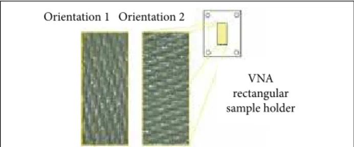
ELECTROMAGNETIC CHARACTERIZATIONhe electromagnetic behavior of epoxy resin/GF prepreg was measured in 2 diferent GF orientations, in order to verify the possible inluence of the arrangement of GF ibers in the interaction with microwaves in the X-band (8.2 to 12.4 GHz). Figure 1 displays the assessed GF orientations.
Equation 1 relates the total energy generated at port i (V i +)
of VNA, i.e., microwave energy emitted from port i and incident on the material located at the VNA rectangular sample-holder, with the portion of energy relected back from the material to the same port (V i –) . hus the total energy measured in dB
refers efectively to the relected wave on the material surface, with no energy emitted from port j (V j + = null). In contrast,
Eq. 2 relates the total energy generated at port i (V i +) of VNA
with the total energy that crosses the material thickness, inally achieving the port j (V j –) located beyond the material. Also,
in this case, the generation of microwave energy from port j is turned of (V + j = null). Equation 2 measures the microwave
energy that propagates through the entire thickness of the material. he portion of energy not received at port j refers to the attenuated energy, due to the relected energy on the material surface returning to the emitting port (Sii) and due to the portion of absorbed energy by the material microstructure (Ea) and the dissipated energy (Ed) in the process, the last being considered null.
Figure 1. Prepreg GF fabric orientations assessed during electromagnetic characterization.
VNA rectangular sample holder
Orientation 2 Orientation 1
Orientation 1 Orientation 2
VNA rectangular sample holder
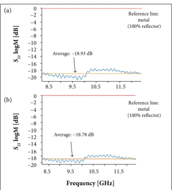
Figure 2a presents average attenuation equal to −18.93 dB, considering the orientation 1, which, according to Eq. 3 (Lee 1991), corresponds to 98.7% of the attenuation, i.e., only 1.3% of the microwave is relected.
highly transparent to the microwaves in the X-band, presenting average attenuation of −18.78 dB. This value indicates an attenuation of 98.7%, and only 1.3% of the signal returns to port 2.
Figure 3 illustrates the electromagnetic properties of the CF/Ni veil, as received, in the frequency range of 8.2 to 12.4 GHz. Taking the average attenuation value of only −0.43 dB for S22 as basis, the material in question presents relector behavior, and 90.7% of wave energy is relected on the CF/Ni veil surface. his relector behavior is more pronounced in frequencies below 10.3 GHz as can be seen in Fig. 3a.
Figure 2.S
22 curves versus frequency for the epoxy/GF
prepreg with GF orientation (a) 1 and (b) 2.
–2 0
–4 –6 –8 –10 –12 –14 –16 –18 –20
8.5 9.5 10.5
Frequency [GHz] 11.5
8.5 9.5 10.5 11.5
Reference line: metal
(100% reflector)
Reference line: metal (100% reflector) Average: −18.93 dB
Average: −18.78 dB
S22
logM [dB]
–20 –4 –6 –8 –10 –12 –14 –16 –18 –20 S22
logM [dB]
he epoxy resin/GF prepreg transmission (S24 andS42) was also measured, and the results conirm the low relectivity of the material, with average attenuation values through the material of only −0.09 dB, which, according to Eq. 3, indicates that 98% of the microwave is transmitted through the prepreg, independently of the incident wave side on the material (S24is equal S42). The parameter S44 was also measured (−18.1 dB for orientations 1 and 2). hese results are similar to those shown in Fig. 2. herefore, the epoxy resin/GF prepreg can be applied during manual lamination process on both sides and at any of the 2 fibers orientations evaluated in this paper, with no impact on the material-microwave interaction. Based on the scattering parameters of the epoxy resin/GF prepreg, it is verified a low reflector behavior (S22 equal to S44 and highly attenuated) and a high transmission of microwaves through the laminate (S24 and S42 near to 0 dB of attenuation). Considering the well-known resistance of this material in deteriorative conditions, such as ultraviolet radiation (UV) exposure (Zainuddin et al. 2011), moisture absorption (Botelho et al. 2008), and thermal degradation (Silveira 2016), the studied prepreg shows potential application as outer layer of EMI structures.
Figure 3. Curves of (a) S
22 and (b) S24 versus frequency of
the CF/Ni veil, as received.
Reference line: metal
(100% reflector)
Reference line: metal (100% trasnmitter) Average: −0.43 dB
Average: −32.65 dB
8.5 9.5 10.5 11.5
8.5 9.5 10.5 11.5
Frequency [GHz]
S22
logM [dB]
S24
logM [dB]
–0.10 0.00
0
–10
–20
–30
–40 –0.20
–0.30
–0.40
–0.50
–0.60
Figure 3b presents the S24parameter. he average value of −32.7 dB corresponds to 99.95% of attenuation, i.e., the signal emitted from port 4 does not cross the CF/Ni veil towards port 2. Correlating this result with the S22 data, it is clear that the signal is practically all relected on the veil surface.
he S44 and S42 parameters were also measured: −0.46 and −32.5 dB average values, respectively. Comparing these values with those presented in Fig. 3, the relection and transmission present similar behavior independently of the incidence side of the elec-tromagnetic wave on the CF/Ni veil, for frequencies ranging from 8.2 to 12.4 GHz. Based on this information, the veil lamination process can be performed with no worries related with the la- mination side previously to the hot-compression molding process.
ENERGY DISPERSIVE SPECTROSCOPY
Once identiied the high relectivity of the CF/Ni veil, as received, acid attacks were conducted, aiming the removal of (a)
(a)
(b)
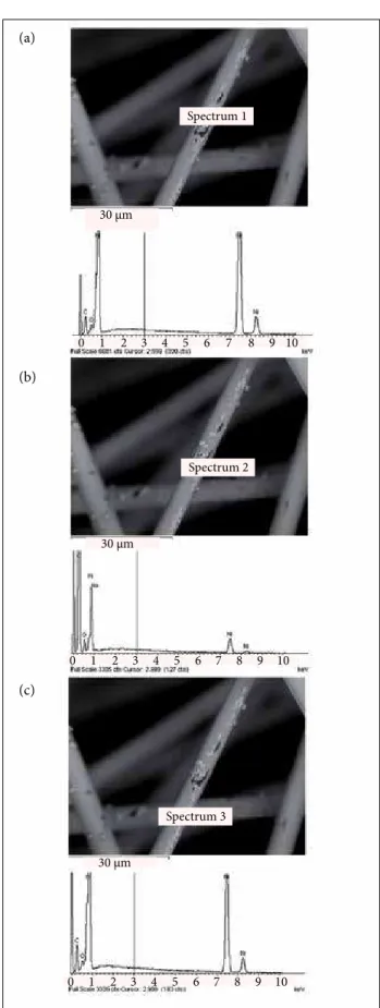
the Ni layer from the CF surface. his procedure was an attempt to decrease the relector behavior of the veil, which, in turn, could lead the material to a condition of greater absorption or transmission of electromagnetic waves in the X-band, providing ield of application in RAS. Figure 4 shows representative SEM/ EDS chemical mapping in 3 diferent regions of the CF/Ni veil as received, representative of the veil in its totality. Figure 4a exhibits non-uniform region formed with the presence of deposition and accumulation of Ni (Spectrum 1). Figure 4b presents exposed CF (Spectrum 2), and Fig. 4c is representative of a region with uniform and continuous Ni coating (Spectrum 3). Table 2 shows the average content, in mass and atomic percentages, of Ni and other chemical elements related to each of the 3 diferent assessed regions from Fig. 4. he values in Table 2 and the characteristic peaks in Fig. 4a make evident the presence of Ni, indicating high percentage in mass for this metal in the veil, as received. Spectrum from Fig. 4b is related to the black region, with high content (79.2%) of carbon element, where the CF surface is partially exposed. his aspect is attributed to the mechanical removal of Ni layer due to friction between ibers, during the veil handling. his, in turn, is the root cause for the deposition and accumulation of Ni as pointed in Spectrum 1. he chemical content indicated in the spectrum of Fig. 4c, as expected, shows high content of Ni, 72.75% in mass. he EDS spectra also show the presence of O, probably related to the presence of oxides (Burakowski and Rezende 2001) and/or adsorbed gases (An et al. 2013).
At sequence, Fig. 5 presents SEM images and results of chemical mapping via EDS in 3 diferent regions of the CF/Ni veil ater the HNO3 acid attacks.
Table 3 shows the average Ni content determined by SEM/ EDS in the veil exposed to the acid attack during 45 min (V1). Two of the spectra, speciically the Spectra 2 and 3, did not detected the presence of Ni, and the spectrum related to the region pointed in Fig. 5a detected a small percentage of Ni content (0.15% in mass). In addition, it need to be mentioned that the Ni content of the veil attacked in HNO3 solution during 120 min (V2) was also surveyed, with no presence of Ni or only traces (average ~ 0.2% in mass and 0.05% atomic). hese results show that the acid attacks in diferent exposure times were efective in the Ni removal from the CF surface.
he EDS technique of CF/Ni veil ater acid attack also detected traces of other elements; among these contaminants, Cl, Si, and Fe were identiied. he presence of Fe is attributed to the use of a Fe-C steel support to keep the veil surface suspended during the drying process in the oven, at 60 °C for 270 min. In addition,
Spectrum 3 Spectrum 2 Spectrum 1
30 μm
30 μm
30 μm
1
0 2 3 4 5 6 7 8 9 10
1
0 2 3 4 5 6 7 8 9 10
1
0 2 3 4 5 6 7 8 9 10
Figure 4. SEM/EDS analyses of the CF/Ni veil as received. (a) Spectrum 1, (b) Spectrum 2, and (c) Spectrum 3.
(a)
(b)
the comparison of O contents in Tables 2 and 3 shows an increase in this element ater the acid attack. his fact can be explained by oxidation processes during acid attack and high temperatures during drying process in the oven, which may add O element on the surface and/or into the samples (An et al. 2013). he high carbon content determined is expected. Firstly, because the precursor material of the veil is CF; secondly, due to the presence of polyester polymer, used as binder for the CFs in the veil, as can be observed in SEM images (Spectra 1 and 3 from Fig. 5), which has the C as the main chemical element forming its macromolecules.
he 2 veil samples exposed to acid attacks had their scattering parameters measured. Figure 6a is representative of the S22 curves versus frequency for veils V1 and V2. his igure shows that the S22 curve for the veils submitted to the acid attack moved downward in relation to the original veil, represented by the black curve in Fig. 6 (−0.43 dB, ~ 91% of relectivity), therefore indicating the drop in the relectivity of the veils exposed to the acid treatments. Speciically for the veil sample exposed to the acid attack during 45 min (V1), the average S22 is −1.13 dB, in other words, an average relectivity of 77%. hus, it was found
100 μm
100 μm
100 μm
1 2 3 4 5 6 7 8 9
Spectrum 1
Spectrum 2
Spectrum 3
1 2 3 4 5 6 7 8 9
1 2 3 4 5 6 7 8 9
*Regions indicated in Fig. 5.
Figure 5. SEM/EDS analyses of the CF/Ni veil after acid attack. (a) Spectrum 1, (b) Spectrum 2, and (c) Spectrum 3.
Table 3. Chemical contents in mass and atomic
percentages determined by EDS of the CF/Ni veil after the acid attack.
Element
% Mass % Atomic
Figure 5a*
Figure 5b
Figure 5c
Figure 5a
Figure 5b
Figure 5c
C 63.07 84.19 71.8 69.8 88.1 77.8
O 35.87 14.47 26.43 29.8 11.4 21.5
S 0.91 0.52 1.77 0.37 0.21 0.70
Ni 0.15 -- -- 0.03 --
--Si -- 0.19 -- -- 0.08
--Cl -- 0.46 -- -- 0.16
--Fe -- 0.17 -- -- 0.05
--Element
% Mass % Atomic
Figure 4a*
Figure 4b
Figure 4c
Figure 4a
Figure 4b
Figure 4c
C 16.7 79.2 24.5 47.7 88.5 59.16
O 2.2 10.9 2.75 4.8 9.15 4.97
Ni 81.1 9.6 72.75 47.5 2.2 35.87
Na -- 0.3 -- -- 0.15
--Table 2. Chemical contents in mass and atomic percentages determined by EDS of the CF/Ni veil as received.
*Regions indicated in Fig. 4.
(a)
(b)
a maximum relectivity reduction equal to 14% in comparison with the original CF/Ni veil, as a consequence of the Ni removal. For the veil sample exposed to the acid attack during 120 min (V2), the average S22 is −0.56 dB, corresponding to an average relectivity of ~ 88%.
he S42 transmittance parameters for veils V0, V1, and V2 were also measured, and the results are presented in Fig. 6b. he S42 values show that the transmittance of the veils increases from V0, through V2, and upward to V1.herefore veils ater acid attacks present lower attenuation of microwaves through its microstructure. his behavior was expected based on S22 results and Eq. 4.
Now the study is focused on understanding the electromag-netic behavior of the epoxy resin/GF/CF/Ni laminates when impinged by microwaves. According to the literature, when a wave reaches a structure, wave displacements around its axis of propagation may occur, followed by multiple relections into the laminate. his phenomenon can contribute to phase can-cellation between the incident and the relected wave, leading to the signal attenuation and approaching the material to the necessary conditions for application in RAS (Zhang et al. 2015).
Figures 7 present the S22 and S44 curves versus frequency for the laminates presented in Table 1. In these igures it is observed that the P/V2/P2 laminate presents the lowest value of attenuation (S44 ~ 0 dB), featuring no attenuation and relectivity close to 100%. he greatest average attenuation occurs for the P/V1/P2
laminate (S22 = −0.39 dB) when the electromagnetic waves are emitted from port 2, i.e., composite side with 1 prepreg layer and V1 layer exposed to the incident wave. hus, the lowest average relectivity among all these laminates is equal to 91.4%. Also, for the laminate P3/V0/P4, it is observed an attenuation peak (S22 = −0.82 dB) of electromagnetic wave with frequency equal to 9.7 GHz, i.e., 82.8% of relectivity at this speciic frequency.
From the investigation and based on the electromagnetic characterization results, e.g., S22 and S44, it was found that the processed laminates do not present desired properties for potential development of RAS. However, the processed laminates combine low thickness (between 0.36 mm for P/V1/P2 and 1.08 mm for P2/V2/P + P/V1/P2 + P/V0/P2), light weight, structural properties, and, as important as the other mentioned properties, signiicant relector behavior (low attenuation for Sii parameters, average relection between 91.4 and 100% of incident microwave in the X-band). In this case, the studied materials present potential for application as multifunctional composites in EMI shielding of buildings, aircrat, and space components.
Figure 6.S
22 (a) and S42 (b) curves versus frequency for
the CF/Ni veil after acid attacks.
Figure 7.S
22 (a) and S44 (b) parameters versus frequency
for GF/epoxy resin/CF/Ni laminates. V0
V1
V2
Reference line: metal (100% reflector)
Reference line: metal (100% transmitter)
8.5 9.5 10.5 11.5
8.5 9.5 10.5 11.5
Frequency [GHz]
S22
veils after
acid attacks [dB]
S42
veils after
acid attacks [dB]
0.0 –0.1 –0.2 –0.3 –0.4 –0.5 –0.6 –0.7 –0.8 –0.9 –1.0 –1.1 –1.2
0 –4 –8 –12 –16 –20 –24 –28 –32
S44
logM [dB]
S22
logM [dB]
8.5 9.5 10.5 11.5
8.5 0.0 –0.1
–0.1 –0.2 –0.3
–0.2 –0.3 –0.4 –0.5 –0.6 –0.7 –0.8
–0.4 –0.5 –0.6 –0.7 –0.8 0.1 0.0
9.5 10.5 11.5
P/V0/P2
P3/V0/P4
P/V1/P2
P3/V1/P4
P/V2/P4 P3/V2/P4
P3/V1/P4 +P/V0/P2
P2/V2/P+P/V1/P2 +
+ P/V0/P2
Frequency [GHz]
CONCLUSIONS
he results presented in this research allow concluding that the epoxy resin/GF fabric prepreg can be applied as outer layer of RAS, since this material allows the transmission, through (a)
(a)
(b)
its microstructure, of 98.7% of electromagnetic waves in the frequency range of 8.2 to 12.4 GHz. he CF/Ni veil used in this research is predominantly relective (~ 91%). Acid treatments of CF/Ni veil were efective in the Ni removal from the CF surface, as conirmed via EDS, with 13.6% of maximum decrease in relector behavior of the CF veil subjected to acid treatment in 5.0 mol/L HNO3 solution during 45 min. Hence, even ater the complete removal of Ni metallized layer, the CF veil still presented low attenuation for Sii parameters, and it is not adequate for application in RAS, when combined with the epoxy resin/GF fabric prepreg. On the other hand, the results indicate compatibility for processing light-weight and low-thickness relective multifunctional composites based on epoxy resin/GF/ CF/Ni, designed for EMI shielding applications, for example, in buildings, communication, automation, bio-medicine, and aerospace areas. Considering that the studied composites were processed based on continuous GF fabric that presents good mechanical properties, and CF/Ni veil with relector behavior for microwaves in X-band, multifunctional composites with intrinsic structural and EMI properties have been developed.
ACKNOWLEDGEMENTS
The authors are grateful to the Conselho Nacional de Desenvolvimento Científico e Tecnológico (CNPq; Proc.: 303287/2013-6, 303559/2012-8), Coordenação de Aperfeiçoamento de Pessoal de Nível Superior/Programa Professor Visitante Nacional Sênior (CAPES/PVNS), Laboratório de Guerra Eletrônica (LAB-GE) at the Instituto Tecnológico de Aeronáutica (ITA), and Laboratório de Análise de Imagens de Materiais (LAIMat) at the Faculdade de Engenharia of the Universidade Estadual Paulista “Júlio de Mesquita Filho” (UNESP), Guaratinguetá Campus, Brazil.
AUTHOR’S CONTRIBUTION
All authors conceived the idea as well as contributed to design creation, manufacturing, characterizations, data acquisition, results analysis, and comments on the manuscript.
REFERENCES
An H, Feng B, Su S (2013) Effect of monolithic structure on CO2 adsorption
performance of activated carbon iber-phenolic resin composite: A simulation study. Fuel 103:80-86. doi: 10.1016/j.fuel.2011.06.076
Balaraju JN, Radhakrishnan P, Ezhilselvi V, Kumar AA, Chen Z, Surendran KP (2016) Studies on electroless nickel polyalloy coatings over carbon ibers/CFRP composites. Surf Coating Tech 302:389-397. doi: 10.1016/j.surfcoat.2016.06.040
Bayrakdar H (2011) Complex permittivity, complex permeability and microwave absorption properties of ferrite-parafin polymer composites. J Magn Magn Mater 323(14):1882-1885. doi: 10.1016/j. jmmm.2011.02.030
Botelho EC, Rezende MC, Pardini LC (2008) Hygrotermal effects evaluation using the iosipescu shear test for glare laminates. J Braz Soc Mech Sci Eng 30(3):213-220. doi: 10.1590/S1678-58782008000300006
Bugnet B, Costa M, Doniat D, inventors; Porous structures having a pre-metallization conductive polymer coating and method of manufacture. 2001 Sept 18. United States Patent US 6290832 B1.
Burakowski L, Rezende MC (2001) Modiicação da rugosidade de ibras de carbono por método químico para aplicação em compósitos poliméricos. Polímeros 11(2):51-57. doi: 10.1590/S0104-14282001000200006
Cao M-S, Song W-L, Hou Z-L, Wen B, Yuan J (2010) The effects of temperature and frequency on the dielectric properties, electromagnetic interference shielding and microwave-absorption of short carbon iber/silica composites. Carbon 48(3):788-796. doi: 10.1016/j. carbon.2009.10.028
Chan KL, Mariatti M, Lockman Z, Slim LC (2011) Effects of the size and iller loading on the properties of copper- and silver-nanoparticle-illed epoxy composites. J Appl Polymer Sci 121(6):3145-3152. doi: 10.1002/app.33798
Chen Z, Xu C, Ma C, Ren W, Cheng H-M (2013) Lightweight and lexible graphene foam composites for high-performance electromagnetic interference shielding. Adv Mater 25(9):1296-1300. doi: 10.1002/ adma.201204196
Chin WS, Lee DG (2007) Development of the composite RAS (radar absorbing structure) for the X-band frequency range. Compos Struct 77(4):457-465. doi: 10.1016/j.compstruct.2005.07.021
Choi I, Kim JG, Seo IIS, Lee DG (2012) Radar absorbing sandwich construction composed of CNT, PMI foam and carbon/epoxy composite. Compos Struct 94(9):3002-3008. doi: 10.1016/j. compstruct.2012.04.009
Chung DDL (2012) Carbon materials for structural self-sensing, electromagnetic shielding and thermal interfacing. Carbon 50(9):1972-2012. doi: 10.1016/j.carbon.50(9):1972-2012.01.031
Deng H, Lin L, Ji M, Zhang S, Yang M, Fu Q (2014) Progress on the morphological control of conductive network in conductive polymer composites and the use as electroactive multifunctional materials. Progr Polymer Sci 39(4):627-655. doi: 10.1016/j. progpolymsci.2013.07.007
Gallo GJ, Thostenson ET (2015) Electrical characterization and modeling of carbon nanotube and carbon iber self-sensing composites for enhanced sensing of microcracks. Materials Today Communications 3:17-26. doi: 10.1016/j.mtcomm.2015.01.009
Gibson RF (2010) A review of recent research on mechanics of multifunctional composite materials and structures. Compos Struct 92(12):2793-2810. doi: 10.1016/j.compstruct.2010.05.003
Hyde MW, Bogle AE, Havrilla MJ (2014) Nondestructive characterization of Salisbury screen and Jaumann absorbers using a clamped rectangular waveguide geometry. Measurement 53:83-90. doi: 10.1016/j.measurement.2014.03.025
Jacob J, Chia LHL, Boey FYC (1995) Thermal and non-thermal interaction of microwave radiation with materials. J Mater Sci 30(21):5321-5327. doi: 10.1007/BF00351541
Jang H-K, Choi W-H, Kim C-G, Kim J-B, Lim D-W (2014) Manufacture and characterization of stealth wind turbine blade with periodic pattern surface for reducing radar interference. Compos Part B-Eng 56:178-183. doi: 10.1016/j.compositesb.2013.08.043
Jenn DC (2005) Radar and laser cross section engineering. 2nd ed. Reston: AIAA (Education Series).
Joffe EB, Lock K-S (2010) Grounds for grounding: a circuit-to-system handbook. IEEE Electromagnetic Compatibility Society. New Jersey: John Wiley & Sons.
Karmel PR, Colef GD, Camisa RL (1998) Introduction to electromagnetic and microwave engineering. New York: Wiley.
Lan M, Cai J, Zhang D, Yuan L, Xu Y (2014) Electromagnetic shielding effectiveness and mechanical property of polymer-matrix composites containing metallized conductive porous lake-shaped diatomite. Compos Part B-Eng 67:132-137. doi: 10.1016/j.compositesb.2014.06.029
Lee C-S, Yang C-L (2014) Thickness and permittivity measurement in multi-layered dielectric structures using complementary split-ring resonators. IEEE Sensor J 14(3):695-700. doi: 10.1109/ JSEN.2013.2285918
Lee S-E, Lee W-J, Oh K-S, Kim C-G (2016) Broadband all iber-reinforced composite radar absorbing structure integrated by inductive frequency selective carbon iber fabric and carbon-nanotube-loaded glass fabric. Carbon 107:564-572. doi: 10.1016/j.carbon.2016.06.005
Lee SM (1991) International encyclopedia of composites. New York: VCH Publishers. Vol. 4.
Liao SY (1990) Microwave devices & circuits. 3rd ed. Upper Saddle River: Prentice-Hall.
Micheli D, Apollo C, Pastore R, Marchetti M (2010) X-Band microwave characterization of carbon-based nanocomposite material, absorption capability comparison and RAS design simulation. Compos Sci Tech 70(2):400-409. doi: 10.1016/j.compscitech.2009.11.015
Mishra M, Singh AP, Gupta V, Chandra A (2016) Tunable EMI shielding effectiveness using new exotic carbon: Polymer composites. J Alloy Comp 688:399-403. doi: 10.1016/j.jallcom.2016.07.190
Nangia RK, Palmer ME (2005) A comparative study of UCAV type wing planforms-aero performance and stability considerations. Paper presented at: 23rd AIAA Applied Aerodynamics Conference; Toronto, Canada.
Nicolson AM, Ross GF (1970) Measurement of the intrinsic properties of materials by time-domain techniques. IEEE T Instrum Meas 19(4):377-382. doi: 10.1109/TIM.1970.4313932
Paiva JMF, Mayer S, Rezende MC (2005) Evaluation of mechanical properties of four different carbon/epoxy composites used in aeronautical ield. Mater Res 8(1):91-97. doi: 10.1590/S1516-14392005000100016
Qin F, Brosseau C (2012) A review and analysis of microwave absorption in polymer composites illed with carbonaceous particles. J Appl Phys 111(061301). doi: 10.1063/1.3688435
Seo IIS, Chin WS, Lee DG (2004) Characterization of electromagnetic properties of polymeric composite materials with free space method. Compos Struct 66(1-4):533-542. doi: 10.1016/j. compstruct.2004.04.076
Shen G, Xu Z, Li Y (2006) Absorbing properties and structural design of microwave absorbers based on W-type La-doped ferrite and carbon iber composites. J Magn Magn Mater 301(2):325-330. doi: 10.1016/j. jmmm.2005.07.007
Silveira DC (2016) Obtenção e caracterização de estruturas absorvedoras de micro-ondas baseadas em laminado de ibra laminado de ibra de vidro/resina epoxy/véu de C/Ni (Master’s thesis). Guaratinguetá: Universidade Estadual Paulista “Júlio de Mesquita Filho”.
Silveira DC (2015) Processing and characterization of structural and electromagnetic microwave absorber multifunctional composite based on GF/epoxy/CF/Ni. Proceedings of the 2ª Jornada de Iniciação Cientíica da Pós-Graduação, UNESP, Faculdade de Engenharia de Guaratinguetá [accessed 2016 April 04]. https://www.researchgate. net/publication/282671863_Processing_and_characterization_of_ structural_and_electromagnetic_microwave_absorber_multifunctional_ composite_based_on_GFEpoxyCFNi
Soethe VL, Nohara EL, Fontana LC, Rezende MC (2011) Radar absorbing materials based on titanium thin ilm obtained by sputtering technique. J Aerosp Technol Manag 3(3):279-286. doi: 10.5028/jatm.2011. 03030511
Su Y, Zhou B, Liu L, Lian J, Li G (2014) Electromagnetic shielding and corrosion resistance of electroless Ni-P and Ni-P-Cu coatings on polymer/carbon iber composites. Polymer Compos 36(5):923-930. doi: 10.1002/pc.23012
Sunitha JN, Rajesh CS, Rai SK (2016) Electromagnetic interference shielding effectiveness and electrical conductivity of Ni coated PCABS/ PPS composites with reinforcement of carbon ibre. Polymer Polymer Compos 24(1):57-63.
Tang L-C, Wan Y-J, Peng K, Pei Y-B, Wu L-B, Chen L-M, Shu L-J, Jiang J-X, Lai G-Q (2013) Fracture toughness and electrical conductivity of epoxy composites illed with carbon nanotubes and spherical particles. Compos Part A-Appl S 45:95-101. doi: 10.1016/j.compositesa.2012.09.012
Thomassin J-M, Jérôme C, Pardoen T, Bailly C, Huynen I, Detrembleur C (2013) Polymer/carbon based composites as electromagnetic interference (EMI) shielding materials. Mater Sci Eng R Rep 74(7):211-232. doi: 10.1016/j.mser.2013.06.001
Tzeng S-S, Chang F-Y (2001) EMI shielding effectiveness of metal-coated carbon iber-reinforced ABS composites. Mater Sci Eng 302(2):258-267. doi: 10.1016/S0921-5093(00)01824-4
Wan D, Bie S-W, Zhou J, Xu H, Xu Y, Jiang J (2015) A thin and broadband microwave absorber based on magnetic sheets and resistive FSS. Progress in Electromagnetics Research C 56:93-100. doi: 10.2528/ PIERC14122203
Xu H, Bie S, Xu Y, Yuan W, Chen Q, Jiang J (2016) Broad bandwidth of thin composite radar absorbing structures embedded with frequency selective surfaces. Compos Part A-Appl S 80:111-117. doi: 10.1016/j. compositesa.2015.10.019
Zainuddin S, Hosur MV, Barua R, Kumar Ashok, Jeelani S (2011) Effects of ultraviolet radiation and condensation on static and dynamic compression behavior of neat and nanoclay infused epoxy/glass composites. J Compos Mater 45(18):1901-1918. doi: 10.1177/0021998310394693
Zang Y, Xia S, Li L, Ren G, Chen Q, Quan H, Wu Q (2015) Microwave absorption enhancement of rectangular activated carbon ibers screen composites. Compos Part B-Eng 77:371-378. doi: 10.1016/j. compositesb.2015.03.059