Marian Wiercigroch
[email protected] University of Aberdeen, King’s College Department of Engineering Centre for Applied Dynamics Research
Aberdeen AB24 3UE, Scotland. UK
Applied Nonlinear Dynamics of
Non-Smooth Mechanical Systems
This paper introduces practically important concept of local non-smoothness where any dynamical system can be considered as smooth in a finite size subspace of global hyperspaceΩ. Global solution is generated by matching local solutions obtained by standard methods. If the dynamical system is linear in all subspaces then an implicit global analytical solution can be given, as the times when non-smoothness occurs have to be determined first. This leads to the necessity of solving a set of nonlinear algebraic equations. To illustrate the non-smooth dynamical systems and the methodology of solving them, three mechanical engineering problems have been studied. Firstly the vibro-impact system in a form of moling device was modelled and analysed to understand how the progression rates can be maximised. Periodic trajectories can be reconstructed as they go through three linear subspaces (no contact, contact with progression and contact without progression). In the second application frictional chatter occurring during metal cutting has been examined via numerical simulation method. The analysis has shown that the bifurcation analysis can be very useful to make an appropriate choice of the system parameters to avoid chatter. The last problem comes from rotordynamics, where nonlinear interaction between the rotor and the snubber ring are studied. The results obtained from the developed mathematical model confronted with the experiment have shown a good degree of correlation.
Keywords: Nonlinear dynamics, non-smooth systems, mechanical vibrations
Introduction 1
Most of real systems are nonlinear and their nonlinearities can be manifested in many different forms. One of the most common in mechanics is the non-smoothness. One may think of the noise of a squeaking chalk on a blackboard, or more pleasantly of a violin concert. Mechanical engineering examples include noise generation in railway brakes, impact print hammers, percussion drilling machines or chattering of machine tools. These effects are due to the non-smooth characteristics such as clearances, impacts, intermittent contacts, dry friction, or combinations of these effects.
Non-smooth dynamical systems have been extensively studied for nearly three decades showing a huge complexity of dynamical responses even for a simple impact oscillator or Chua's circuit. The theory of discontinuous and non-smooth dynamical systems has been rapidly developing and now we are in much better position to understand those complexities occurring in the non-smooth vector fields and caused by generally discontinuous bifurcations. There are numerous practical applications, where the theoretical findings on nonlinear dynamics of non-smooth systems have been applied in order to verify the theory and optimize the engineering performance. However from a mathematical point of view, problems with non-smooth characteristics are not easy to handle as the resulting models are dynamical systems whose right-hand sides are discontinuous, and therefore they require a special mathematical treatment and robust numerical algorithms to produce reliable solutions. Practically, a combination of numerical, analytical and semi-analytical methods is used to solve and analyse such systems and this particular aspect will be explored here.
The main aim of the paper is to outline a general methodology for solving of non-smooth dynamical systems, and to apply it to practical problems. The methodology will be illustrated and examined through three case studies. Firstly periodic responses of a drifting vibro-impact system with drift will be investigated through a novel semi-analytical method, developed by Pavlovskaia and Wiercigroch (2003a), which allows to determine the favourable
Presented at XI DINAME – International Symposium on Dynamic Problems of Mechanics, February 28th - March 4th, 2005, Ouro Preto. MG. Brazil. Paper accepted: June, 2005. Technical Editors: J.R.F. Arruda and D.A. Rade.
operating conditions. The model accounts for visco-elastic impacts and is capable to mimic dynamics of a bounded progressive motion (a drift). Then the frictional chatter in orthogonal metal cutting will be modelled and analysed using numerical and analytical methods (see Wiercigroch and Krivtsov, 2001). In this paper an extensive nonlinear dynamic analysis has been performed giving some new light on the frictional chatter occurrence, i.e. that the discontinuous character of the friction force is essential for the chatter generation. Finally, the dynamic responses of a Jeffcott rotor system with bearing clearances will be examined (see Karpenko et al., 2002a and Pavlovskaia et al., 2004).
Nomenclature
a = constant of dynamic component b = constant of static component c = damping coefficient d = dry friction force e = eccentricity vector f = vector function f = external force h = gap
H = Heaviside step function k = stiffness coeficient m = mass
p = vector of system parameters R = radius vector
q = cutting parameter
ɺ
x = velocity vector x = state space vector X = subspace
x = absolute displacement in the x-direction x′ = absolute velocity in the x-direction y = absolute displacement in the y-direction
y′ = absolute velocity in the y-direction v = absolute displacement of the slider bottom z = absolute displacement of the slider top
Greek Symbols
α
= stiffness ratio
ε
= offset
η
κ
= stiffness ratio
✁
= static friction coeficient
ξ
= damping ratio
φ
= phase angle
ω
= rotational frequency
τ
= time
✝ τ
= time interval
Subscripts
r relative to the rotor s relative to the snubber ring x relative to component in x direction y relative to component in y direction
Non-Smooth Dynamical Systems
In many engineering applications, characteristics of the system can be either discontinuous or non-smooth. As well-known examples, one may point an oscillator with clearance analysed in (Peterka & Vacik, 1992), piecewise linear oscillators (Shaw & Holmes, 1983; Wiercigroch & Sin, 1998, Pavlovskaia et al., 2001), Jeffcott rotor with bearing clearances (Gonsalves et al, 1995, Karpenko et al., 2002a, Pavlovskaia et al., 2004), systems with Coulomb friction (Feeny, 1992; Wiercigroch, 1994) and metal cutting processes (Grabec, 1988, Wiercigroch, 1997). General methodology of describing and solving non-smooth dynamical system can be found in (Wiercigroch & de Kraker, 2000). It includes modelling of non-smooth systems by discontinuous functions and modelling of discontinuities by smooth functions. In the latter case extra care is required as smoothing discontinuities can produce a ghost solution (Karpenko et al., 2002a). The first approach considers first a dynamical system, which is continuous in global hyperspace Ω, and in autonomous form can be described as
( )
, =xɺ f x p (1)
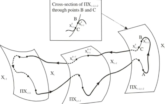
where x=[x1,x2,…,xn]T is the state space vector, p=[p1,p2,…,pm]T is a vector of the system parameters, and f=[f1,f2,…,fn]T is the vector function which is dependent upon the process being modelled. Then we assume that the dynamical system (1) is continuous but only in N subspaces Xi of the global hyperspace Ω (see Fig. 1), therefore, the right hand side of Eq.(1) will be piecewise smooth. For each subspace Xi when x=Xi the right hand side of Eq.(1) will be different function equal to fi (x, p) where i=[1,...,N].
ΠXi,i+1
ΠXi+1,i+2
ΠXi-1,i
Xi-1
Xi
Xi+1
Xi+2
A B
C
xk+1
(-)
xk+1
(+)
xk
(+)
xk
(-)
C B
xk
(+)
xk
(-)
Cross-section of X through points B and C
Π i+1,i+2
Figure 1. Trajectory of a non-smooth dynamical system.
Vibro-Impact Systems
Vibro-impact systems are inherently nonlinear and have been widely used in civil and mechanical engineering applications. One may give examples of ground moling machines, percussive drilling, ultrasonic machining and mechanical processing (cold and hot forging). In the past all these machines and processes have been designed based on linear dynamic analysis.
Imagine for example, a vibro-impact system driving a pile into the ground. During its operation the driving module moves downwards, and its motion can be viewed as a sum of a progressive motion and bounded oscillations. The simplest physical model exhibiting such behaviour is comprised of a mass loaded by a force having static and harmonic components, and a dry friction slider. This model was introduced and preliminary analysed in Krivtsov & Wiercigroch (1999, 2000). Despite its simple structure, a very complex dynamics was revealed. The main result from that work was a finding that the best progression occurs when the system responds periodically. A more realistic model including visco-elastic properties of the ground and its optimal periodic regimes were studied in Pavlovskaia et al. (2001, 2003a, 2003b, 2004).
Modelling of Vibro-Impact Moling
As a first approximation a vibro-impact moling system may be represented as an oscillating mass with a frictional visco-elastic slider as shown in Fig. 2a. The frictional visco-elastic slider models well the hysteretic soil resistance depicted in Fig. 2b. This model allows mimicking the separation between the mole head and the front face of the hole.
A mass m is driven by an external force f containing static b and dynamic a cos(ωτ + ϕ) components. The weightless slider has a linear visco-elastic pair of stiffness k and damping c. As has been reported in Pavlovskaia et al. (2001) the slider drifts in stick-slip phases where the relative oscillations between the mass and the slider are bounded ranging from periodic to chaotic motion. Similarly to the stick-slip phenomenon, the progressive motion of the mass occurs when the force acting on the slider exceeds the threshold of the dry friction force d, x, z, v represent the absolute displacements of the mass, slider top and slider bottom, respectively. It is assumed that the model operates in a horizontal plane, or the gravitational force is compensated. At the initial moment τ = 0 there is a distance between the mass and the slider top called gap, g.
Plastic motion Elastic
motion
S
oi
l
re
si
st
an
ce
Penetration
c k
Pf
(a) (b)
m
c k
Pf
P=P cos( t+ )+Pd Ω ϕ s
Xb
Xt
Xm
Figure 2. (a) Physical model of drifting vibro-impact system, (b) model of soil.
modes can be written using Heaviside step functions Hi in the following form:
(
)
(
)
(
)(
)
(
)
(
)
1 2 3 1 3
1 1
1 3 4 ,
cos (2 )H H 1 H H H ,
H 1 H 2 ,
H H H 1 2 ,
,
x y
y a s b y z
z y z
y z
s
ϕ ξ
ξ ξ ω
′ =
′ = + + − + − − −
′ = − − −
′ + −
′ =
(2)
where
(
)
(
)
(
)
( )
1 2
3 4
H , H 2 ,
H 2 1 , H
H x z e H y z
H y z H y
ξ ξ
= − − = +
= + − =
The basic function of the investigated system is to penetrate through soil. Despite the fact that the considered model has only two degrees-of-freedom, its dynamics is very complex. Since displacements of the system elements are moving from the origin, the mass velocity has been used to view the structural changes in the system responses due to the fact that it is bounded. The control parameter in form of static force, b proved to be very useful for determining the regions of the best progression.
δ γ
β α
T
IV III
gap
I
IV
II III
I
(a)
0.000 0.125 0.250 0.375 0.500
0 30 60 90 120
0 1500 3000 4500 6000
Di
sp
la
ce
m
en
t,
v
Static force b
P
ro
g
re
ss
io
n
p
er
p
er
io
d
(b)
Figure 3. (a) Four phases of a periodic progressive motion, (b) comparison of the numerical simulation with the semi-analytical method (thick solid line).
The construction of the bifurcation diagrams has brought some practical insight regarding progression rates. Since the system drifts towards larger displacements, v, one way to monitor progression rate is to calculate displacement in a finite time, which in our computations was equal to 50 periods of external loading. As has been reported in (Pavlovskaia et al., 2001), the maximum penetration rate coincides with the point where periodic regime becomes aperiodic. This information has been used to develop a semi-analytical algorithm for determining this point, and it can be found in Pavlovskaia & Wiercigroch (2003). The method constructs a periodic response assuming the global solution is comprised of a sequence of distinct phases for which local analytical solutions are known explicitly. A solution may consist of the following sequential phases (see Fig. 3a): (I) contact with progression, (II) contact without progression, (III) no contact and (IV) contact without progression. Progressions per period were calculated from the numerical simulation of the system dynamics and then compared with the results from the devised semi-analytical method (thick solid line in Fig. 3b). As can be seen from Fig. 3b, a very good correlation between two methods was obtained.
Vibrations in Metal Cutting
Despite the continuing effort in the field, and generation of new theories, there is no consistent explanation for the existence of chatter. The fundamental reason behind it is the complexity of the chip-formation process, where the following strongly nonlinear phenomena are interrelated and dependent: temperature-dependent plasticity; temperature- and velocity-dependent friction; nonlinear stiffness of machine tools; regenerative effects; and intermittency of the cutting process. There are two different types of chatter: primary and secondary. Primary chatter is caused mainly by the variable shear stresses in the primary and secondary plastic deformation zones, and the frictional effects of the chip acting on the rake surface due to the relative motion between the workpiece and tool. Secondary chatter is predominantly a result of the regenerative effects, where the workpiece geometry from the previous pass influences the dynamics of the next pass.
The most influential work on the dynamics of machine tools and cutting processes was conducted in the mid forties by Merchant (1945), and later by Russians. The studies carried out by Zorev (1956) and Kudinov (1963) are good examples of those investigations, where the dynamics characteristics of the cutting process play a key role in process stability. Contrary to this approach, there is a significant body of research assuming that the machine-tool structure is responsible for the dynamic instabilities (e.g. Tlusty, 1986). Recent investigations into nonlinear dynamics have shown an existence and importance of chaotic motion occurring in machining. The models by Grabec (1988), Wiercigroch (1997) and Wiercigroch & Krivtsov (2001) have shown evidence of chaotic vibrations, which are mainly due to the nonlinearity of the dry friction and then intermittent contact between the cutting tool and the workpiece.
cutting-process characteristics, is captured by orthogonal cutting, where the cutting edge is parallel to the workpiece and normal to the cutting direction, as depicted in Fig. 4b.
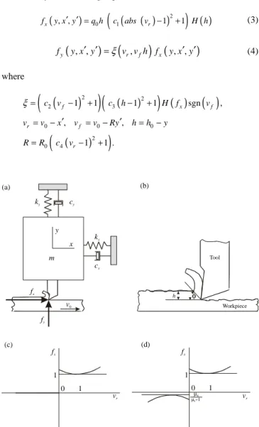
Since fx and fy are mutually related, one can be expressed by the other. This approach was adopted from Hastings et al. (1980), where the cutting forces for a wide class of technical materials are described by the following expressions,
(
)
(
(
( )
)
2)
( )
0 1
, , 1 1
x r
f y x y′ ′ =q h c abs v − + H h (3)
(
, ,)
(
,)
(
, ,)
y r f x
f y x y′ ′ =ξ v v h f y x y′ ′ (4)
where
(
)
(
)
(
(
)
)
( )
( )
(
)
(
)
2 2 2 30 0 0
2
0 4
1 1 1 1 sgn ,
, ,
1 1 .
f x f
r f
r
c v c h H f v
v v x v v Ry h h y
R R c v
ξ = − + − +
′ ′ = − = − = − = − + φ h Tool Workpiece 1 vr 0 fx 1 1 vr 0 fx 1 µ0
µ0+1
(b) (c) (d) (a) m cx kx fy fx x y v0
ky cy
Figure 4. MT-CP system; (a) physical model, (b) chip geometry, (c) former form of fx, (d) new form of fx as a function of the relative velocity vr.
The cutting process starts with an initial depth of cut, h0, where a layer is taken from the workpiece with the constant velocity, v0. Throughout the process it is assumed that the cutting parameters, such as c1, …, c4 and q0 are fixed. The nonlinear relationship between the cutting force, fx, and chip velocity is graphically presented in Fig. 4c where, for vr<0, the excitation force is equal to zero. In reality, this force never disappears completely as there is always a considerable friction force due to the compression force in the vertical spring. To make this approach more realistic, a dry friction force acting in x-direction for the vr < 0 cases needs to be added. On the other hand, Eq.(4) should still be valid to predict the total force, fx for the vr ≥ 0 cases. A modified formula, which satisfies the conditions listed above, is written below and presented graphically in Fig. 4d
(
)
( )
( )
( )
(
)
(
)
( )
0 0 0 0 2 1 1, , sgn
1 1
1 1
x r r
r
f y x y q h H v v
c abs v H h
µ µ µ ′ ′ = + × + + − +
(5)
where µ0 is the static friction coefficient.
Dynamics of the analysed system can be described by a set of two second-order differential equations, which is presented in a non-dimensional form
(
)
(
)
2 , , ,
2 , , ,
x x
y y
x x x f y x y
y y y f y x y
ξ
ξ α α
′′+ ′+ = ′ ′
′′+ ′+ = ′ ′ (6)
where 0 0 2 2 0 0 , , 2 2 , , . y x x y x y
y x y
x y
x
c c
m m
k k c
c m m
ξ ξ
ω ω
α ω ω
= =
= = =
As the analysed system is nonlinear and can exhibit a broad range of responses, it is essential to provide a high-accuracy integration routine. Each time a discontinuity occurs, the precise value of the time has to be calculated in order to provide the correct initial conditions for the next integration step. A standard zero-finder algorithm cannot effectively be applied in this case; therefore the computations were conducted using the method specifically developed for this problem, (see Wiercigroch, 1997). For a given set of parameters and initial conditions, the numerical integration is carried out using the fourth-order Runge-Kutta procedure with a fixed time-step, ∆τ = 0.001, until a discontinuity is detected. Then, based on the type of discontinuity recognized, the precise time value is calculated, either by an inverse interpolation or a bisection routine.
(a)
(b)
(c)
(d)
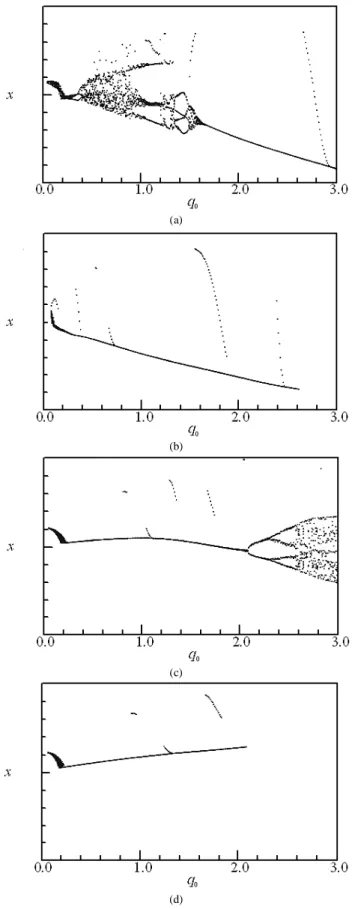
Figure 5. Bifurcation diagrams x = f(q0); (a) αααα = 0.25, (b) αααα = 1, (c) αααα = 4, (d)
α αα α = 16.
Summarizing, for α=0.25, the system dynamics undergoes vast changes. Setting up the stiffness ratio, α, to 1 and 16, the behaviour
is completely different (see Fig. 5b, d). For almost the entire range
of the cutting-force modulus, the system oscillates either periodically or almost periodically, excluding the lower values of q0, where some transient irregular motion occurs. The bifurcation diagrams constructed for α=4 show another example for an unusual behaviour, that is, unidirectional bifurcation. The system bifurcates in the x direction and is stable in the y direction, for q0 between 0.24 and 0.54, despite the fact that the equations of motion are coupled. There is also a shift of the critical point for the x and y directions. For the x direction, the system starts with two bifurcation periods of the doubling type, and then vibrates chaotically. For the y direction, the system, after crossing the critical value, oscillates with period 4, and then becomes chaotic. The bifurcation diagrams depicted in Fig. 5 show that, for α=0.25 and α=1.0, the system, after regaining periodicity, decreases its vibration amplitude with an increase of the cutting force. This fact can be used in the design of the machine tools and control of the cutting processes. For α=16, the system responses are consistent with a traditional understanding of the MT-CP interactions, i.e. higher amplitudes are generated by larger cutting forces.
Nonlinear Oscillations of Jeffcott Rotor with Snubber Ring
In rotor systems non-smoothness may appear due to bearing clearances. This may result in piecewise stiffness characteristics, which can consequently lead to nonlinear behaviour including chaotic motion. The existence of this characteristic implies that there is intermittent contact between the components of the rotor system, which is critical to predict and control their complex behaviour.
Rotor systems with bearing clearances have been studied in the past, where the investigations concentrated primarily on the Jeffcott rotors. In particular, Choy and Padovan (1987), Muszynska and Goldman (1995), Childs (1982) and Chu and Zhang (1997, 1998) paid attention to rub interactions in rotating machinery. Ehrich (1992) investigated spontaneous sidebanding, while Ganesan (1996) looked at the stability analysis. Numerical investigation of the model of the Jeffcott rotor with a snubber ring by Karpenko et al. (2002b) has shown the existence of multiple attractors and fractal basins of attraction. Influence of the preloading and viscous damping of the snubber ring was investigated in Karpenko et al. (2003b) where it was shown how the preloading of the snubber ring could stabilize the dynamic responses.
Rotor System with Bearing Clearances
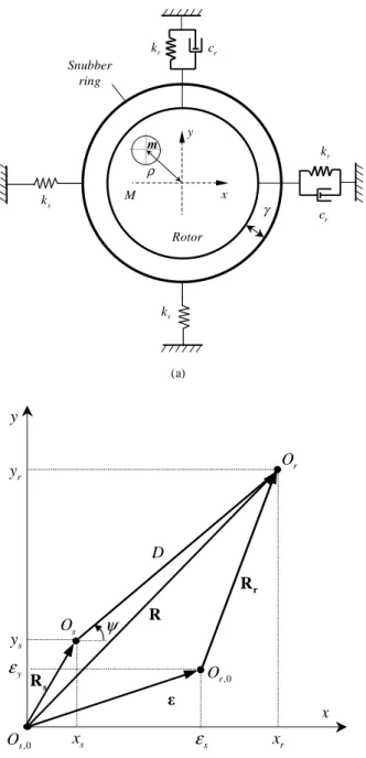
The rotor system (see Karpenko, 2003b) is modelled as a two-degrees-of-freedom piecewise nonlinear planar oscillator, where the rotor makes intermittent contact with the preloaded snubber ring. The physical model and the geometrical description of the model are given in Fig. 6. The excitation of the rotor is provided by an
m
M
k r
s
k
cr
γ
Rotor Snubber
ring
y
x
ρ
k r
cr
k s
(a)
x
D
s
R
sy
s
x
ψ
r
x
,0s
O
,0
r
O
sO
r
R
r
O
ry
x
ε
y
ε
R
y
(b)
Figure 6. (a) Physical model of the Jeffcott rotor with bearing clearances, (b) adopted co-ordinate system.
When rotor moves inside the stator without any interaction with the ring the equations of motion for the rotor and the snubber ring are as follows (Karpenko et al., 2003a)
(
)
(
)
1 0 0
1 0 0
2 2
2 cos ,
2 sin ,
2 0, 2 0.
r r r x
r r r y
s s s s
x x x f
y y y f
x x y y
ξ ε ϕ ητ
ξ ε ϕ ητ
ξ κ ξ κ
′′+ ′+ − = +
′′+ ′+ − = +
′+ = ′+ =
(7)
When the rotor is in contact with the snubber ring there are four unique regimes (see Pavlovskaia et al., 2004), for which the stiffness of the snubber ring for x and y directions differs. Equations of motion can be written as
(
)
(
)
1 , 0 0
2 , 0 0
2 cos ,
2 sin ,
( , ), ( , ).
r r r x s x
r r r y s y
s s r r s s r r
x x x f f
y y y f f
x x x y y y x y
ξ ε ϕ ητ
ξ ε ϕ ητ
′′+ ′+ − + = +
′′+ ′+ − + = +
= =
(8)
In Eqs( 7) and (8), 1 and 2 denote the viscous damping ratios of the rotor and the snubber ring, where fs,x and fs,y are the restoring forces in the snubber ring in x and y direction respectively. The constraints between the rotor and the snubber ring co-ordinates were developed in Pavlovskaia (2004). Equations of motion (8) and (9) have been derived using the following series of assumptions. Firstly dry friction between the ring and rotor has been neglected. Secondly it was assumed that the snubber ring itself is massless, because it is manufactured from aluminium and highly preloaded by compression springs. Thirdly gyroscopic forces are not taken into consideration since no angular motion occurs.
Experimental Verification
In this section sample of extensive experimental studies in Karpenko (2003b) conducted to verify the mathematical model of Jeffcott rotor system with a snubber ring developed at the University of Aberdeen is presented.
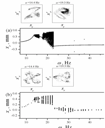
For the bifurcation diagram presented in Fig. 7a comparison of the theoretical (Fig. 7a) and experimental (Fig. 7b) responses shows a number of similarities. In both figures for the low magnitude of the forcing frequency period one motion is observed for f=(7,13.6)Hz and at f=(16.2,17.7)Hz followed by chaotic regimes for f=(13.6,16.2)Hz and f=(17.7,22.8)Hz respectively. In the theoretical and experimental diagrams the width of both periodic and chaotic regimes are the same. After the flip bifurcation at f=22.8Hz the theoretical response becomes periodic up to the end of the diagram. In the experimental bifurcation diagram in Fig. 7b for f=(25.6,32)Hz some kind of quasi-periodic regime was obtained. In both diagrams two cross-sections were examined in the form of Poincaré maps. It is also seen that the theoretical and experimental attractors are similar in shape. However, despite of the shape similarity, there are some differences in the amplitudes of displacements and velocities.
Conclusions
Figure 7. Bifurcation diagrams for the forcing frequency; (a) theoretical, (b) experimental.
Firstly the vibro-impact system in a form of moling device was modelled and anaysed in order to understand how the progression rates can be maximised. Periodic trajectories can be reconstructed as they go through three linear subspaces (no contact, contact with progression and contact with progression). It was shown that the considered model reflects well the dynamics of the vibro-impact system and also the soil resistance curves. A typical nonlinear dynamic analysis has revealed complex behaviour ranging from periodic to chaotic motion. Bifurcation diagrams were constructed using variation of the mass velocity as the displacement has a drift. It was found out that the maximum progression is achieved when system responds periodically with the period of external excitation.
In the second application frictional chatter occurring during orthogonal metal cutting has been examined via numerical simulation method. The physical models consider a dry friction force acting on the cutting edge. The system demonstrates complex dynamic behaviour, which is manifested by the existence of periodic, quasi-periodic, subharmonic and chaotic motion. It was found that some of the bifurcation diagrams couldn’t be classified into standard routes to chaos, however; crisis type transition to chaos is dominating. The analysis has shown that the bifurcation analysis can be very useful to make an appropriate choice of the system parameters to avoid chatter.
The last problem comes from rotordynamics, where nonlinear interactions between the rotor and the snubber ring are studied. The mathematical model neglects the frictional and gyroscopic forces, and concentrates on the dynamic responses caused by interactions between a whirling rotor and a massless snubber ring, which has much higher stiffness than the rotor. The mathematical model has been solved using both the approximate analytical method and numerical by a direct integration of the equations of motion. By employing various techniques such as construction of bifurcation diagrams and Poincaré maps, comparisons are made between the results obtained from the experiment and the theory. The results
obtained showed that a wide variety of motion was exhibited by this system ranging from periodic to chaotic. A good correlation between experimental and theoretical results has been obtained. It was shown that the experiment has confirmed the basic bifurcation scenarios predicted theoretically.
Acknowlegdement
I would like to gratefully acknowledge help I have received from my colleagues and collaborators over the years. I am particularly thankful to Dr E.E. Pavlovskaia of the University of Aberdeen and Dr E.V. Karpenko from Rolls-Royce plc.
References
Childs, D.W., 1982, “Fractional-Frequency Rotor Motion Due to Non-Symmetric Clearance Effects”, Trans. ASME, J. Engng Power, Vol.104, pp. 533-541
Choy, F.K., and Padovan, J., 1987, “Nonlinear Transient Analysis of Rotor-Casing Rub Events”, J. Sound Vibr., Vol.113, pp. 529-545.
Chu, F. and Zhang, Z., 1997, “Periodic, Quasi-Periodic and Chaotic Vibrations of a Rub-Impact Rotor System Supported on Oil Film Bearing”, International Journal of Engineering Sciences, Vol.35 pp. 963-973.
Chu. F. and Zhang, Z., 1998, “Bifurcation and Chaos in a Rub-Impact Jeffcott rotor system”, J. Sound Vibr., Vol.210, pp. 1-18.
Ehrich, F.F., 1992, “Spontaneous Sidebanding in High-Speed Rotordynamics”, Trans. ASME, J. Vibr. Acoust., Vol.114 pp. 498-505.
Feeny, B., 1992, “Non-smooth Coulomb Friction Oscillator”, Physica D, Vol. 59, pp.25-38.
Ganesan, R., 1996, “Dynamic Response and Stability of a Rotor-Support System with Non-Symmetric Bearing Clearances”, Mechanism Machine Theory, Vol.31, pp. 781-798.
Gonsalves, D.H., Neilson, R.D. and Barr, A.D.S., 1995, “A Study of Response of a Discontinuously Nonlinear Rotor System”, Nonlinear Dynamics, Vol.7, pp. 451-470.
Grabec, I., 1988, “Chaotic Dynamics of the Cutting Process”, Int. J. Mach. Tools Manufact., Vol.28, pp. 19-32.
Hastings, W. F., Mathew, P. and Oxley, P. L. B., 1980, “A Machining Theory for Predicting Chip Geometry, Cutting Forces, etc., from Material Properties and Cutting Conditions”, Proc. R. Soc. Lond. A, Vol.371, pp. 569-587.
Karpenko, E.V., Wiercigroch, M., and Cartmell, M.P., 2002a, “Regular and Chaotic Dynamics of a Discontinuously Nonlinear Rotor System”, Chaos, Solitons and Fractals, Vol.13, pp. 1231-1242.
Karpenko, E.V., Wiercigroch, M., Pavlovskaia, E.E. and Cartmell, M.P., 2002b, “Piecewise Approximate Analytical Solutions for a Jeffcott Rotor with a Snubber Ring”, Int. J. Mech. Sci., Vol.44, No.3, pp. 475-488.
Karpenko, E.V., Pavlovskaia, E.E., and Wiercigroch, M., 2003a “Bifurcation Analysis of a Preloaded Jeffcott Rotor”, Chaos, Solitons and Fractals, Vol.15, pp. 407-416.
Karpenko, E.V., 2003b, “Nonlinear Dynamics of a Jeffcott Rotor with Imperfections”, PhD thesis. University of Aberdeen.
Krivtsov, A M, Wiercigroch, M., 1999, “Dry Friction Model of Percussive Drilling”, Meccanica,, Vol.34, pp. 425-434.
Krivtsov, A. M., Wiercigroch, M., 2000, “Penetration Rate Prediction for Percussive Drilling via Dry Friction Model”, Chaos, Solitons and Fractals, Vol.11, pp. 2479-2485.
Kudinov, V. A., 1963, “Dynamic Characteristics of the Metal Cutting Process”, Stanki i Instrument, Vol.10, pp. 1-7. (In Russian.)
Merchant, M. E., 1945, “Mechanics of Metal Cutting Process. Part I. Orthogonal Cutting and a Type-2 Chip”. J. Appl. Phys., Vol.16, pp. 267-275.
Muszynska, A. and Goldman, P., 1995, “Chaotic Responses of Unbalanced Rotor/Bearing/Stator Systems with Looseness or Rubs”, Chaos, Solitons & Fractals, Vol.5 pp. 1683-1704.
Pavlovskaia, E.E., Wiercigroch, M. and Grebogi, C., 2001, “Modelling of an Impact System with a Drift” Phys. Rev. E, Vol.64, 056224 (9 pages).
Pavlovskaia, E.E., and Wiercigroch, M., 2003a “Periodic Solutions Finder for Vibro-Impact Oscillator with a Drift”, J. Sound Vibr, Vol. 267 (4), pp. 893-911.
Pavlovskaia, E.E., Karpenko, E.V. and Wiercigroch, M., 2004, “Nonlinear Dynamics of a Jeffcott Rotor with a Preloaded Snubber Ring”, J. Sound Vibr., Vol.276 No.1-2, pp. 361 – 379.
Peterka, F. and Vacik, 1992, “Transition to Chaotic Motion in Mechanical Systems with Impacts”. J. Sound Vibr., Vol.154, pp. 95-115.
Shaw, S.W., and Holmes, P.J., 1983, “A Periodically Forced Piecewise Linear Oscillator", J. Sound Vibr., Vol.90, pp. 129-155.
Tlusty, J., 1986, “Dynamics of High Speed Milling”, Trans. AMSE J. Engng Industry, Vol.108, pp. 59-67.
Wiercigroch, M., 1994, “A Note on the Switch Function for the Stick-Slip Phenomenon”, J. Sound Vibr., Vol.175, pp. 700.
Wiercigroch, M., 1997, “Chaotic Vibrations of a Simple Model of the Machine Tool-Cutting Process System”, Trans. ASME, J. Vibr. Acoust., Vol.119, pp. 468-475.
Wiercigroch, M. and de Kraker, B. eds., 2000, “Applied Nonlinear Dynamics and Chaos of Mechanical Systems with Discontinuities”, Nonlinear Science Series A, Vol.28. Singapore: World Scientific
Wiercigroch, M. and Krivtsov, A.M., 2001, “Frictional Chatter in Orthogonal Metal Cutting”, Philosophical Transactions of the Royal Society of London: Part A, Vol.359 (1781), pp. 713-738.
Wiercigroch, M., and Sin V.T.W., 1998, “Experimental Study of a Symmetrical Piecewise Base-Excited Oscillator", Trans. ASME, J. Appl. Mech., Vol.65 No.3, pp. 657-663.