1.Harbin Institute of Technology – Harbin, China
Author for correspondence: Zhang Jing | School of Mechatronics Engineering | Harbin Institute of Technology | 92 West Dazhi Street | Nan Gang District | Post Code 150001 Harbin – China | Email: [email protected]
Received: 23/02/13 | Accepted: 09/05/13
Nonlinear Characteristics of Revolute
Joints with Clearance
Liu Rong-qiang1, Zhang Jing1, Guo Hong-wei1, Deng Zong-quan1
ABSTRACT:The nonlinear contact characteristic of revolute joint with clearance can degrade the performance of deployable structure. In this article, tensile and compressive tests are adopted to investigate the accuracies of the simplest conformal model and nonconformal model for contact, which are used to calculate the revolute joint deformation. In order to study the applicability of the two models, different clearances of joints are introduced in the tests. The results of the two contact models do not well agree with the experimental results. A model for the calculation of contact force and deformation of revolute joint, considering geometric constraints and cylinder contact characteristic, is presented. By comparison with the simplest conformal model and nonconformal model for contact, the proposed model is more accurate to calculate the nonlinear contact of revolute joint. The theoretical and experimental analysis of revolute joint with clearance is helpful to improve the reliability of deployable structure simulation.
KEYWORDS: Nonlinear stiffness, Revolute joint, Clearance, Conformal contact.
INTRODUCTION
The deployable structures have always been used to reduce the packaging volume of the spacecraft. Many appendage structures (Larsen et al., 2009; Meguro et al., 2009), such as communication antennas, have been successfully deployed in space. The truss elements of deployable structures are constructed by revolute joints. In order to achieve connection and large-scale rotation of truss elements, there are small clearances in the joints. It affects the performance of deployable structures and causes noise, wear, and vibrations (Ingham and Crawley, 2001; Schwab et al., 2002; Parenti-Castelli and Venanzi, 2005; Flores et al., 2006a,b, 2010; Qi et al., 2010). The presence of clearance in the revolute joints often degrades the structure stiffness and has a significant effect on the dynamic behavior of deployable structures. Formulation for the contact of clearance joint is very important for researchers to study the nonlinear dynamics of structures and simulate the multibody system precisely (Liu et al., 2006). So it is necessary to analyze and calculate the stiffness of clearance joint.
in revolute joints to allow relative rotation between the clevis and tang. The contact force and the deformation of revolute joint with clearance are usually calculated by Hertz model. In this section, the contact model of two cylinders is presented first, which is based on plane strain theory. Figure 1b depicts the contact of revolute joint, in which the radial clearance, ΔR, is defined as difference between the pin and tang radius, R
1 and R2, respectively. It is assumed that the two contact bodies are isotropic materials. The Young’s modulus and Poisson’s ratio of tang and pin are represented by E
1, E2, υ1, and υ2, respectively, a is the contact width and ε is the semiangle of contact
corresponding to the contact relationship.
According to the Hertz laws for two-dimensional contact of cylindrical bodies (Johnson, 1985), two cylinder contact can be simplified from the three-dimensional contact into two-dimensional contact when their axes parallel. The relationship of contact force and width is obtained based on the constraints of contact. The sign of the curvature is related with the shape of the contact surface. When the contact surface is concave or saddle shaped, the radius curvature sign of the contact solid is negative. So the relative radius of the pin and the tang contact can be expressed as
1 2 2
R R R
R R
-=
1 (1)
The equivalent Young’s modulus can be written
2 2
2 1
1 2
1
1 1
E E E
u u
-
-= + (2)
The contact pressure distribution is given by
( )
(
2 2 2)
12
x 2P a x
p
a −
=
π
(3)response of four-bar mechanism with clearance joint, including the impact force and friction. Tian et al., (2009) deduced the lubricant force in lubricated joints based on Reynolds’ equation. In these plane mechanism studies, the Hertz law expression about two spheres has been used to calculate the contact force in revolute joint (Lankarani and Nikravesh, 1990; Jia et al., 2002; Khemili and Romdhane, 2008; Shi and Jin, 2008; Erkaya and Uzmay, 2012; Olyaei and Ghazavi, 2012). It is difficult to obtain accurate contact deformation and load of two cylinders by using sphere contact model and nonconformal contact model. So the rationality of the nonconformal contact model and conformal contact model has to be testified.
The main methods of building the contact model are the elastic theory and discrete method. Based on the contact force model with hysteresis damping given by Lankarani and Nikravesh (1990), Flores and Ambrosio (2004), and Flores et al., (2006a,b) gave the normal contact model of planar revolute
joints and compared different contact models. The contact area and load can be separated into its normal and tangential components (Abdo and Shamseldin, 2005). Discrete method is usually achieved by using finite element method (FEM), which has been used to give the force–displacement relation of sphere and the parameters influence on contact stress (Zhang and Vu-Quoc, 2001; Knight et al., 2002). However, it will take a long time to simulate the contact of joint with FEM.
Because a simple and accurate calculation method has not yet been developed, the particular focus in this article lies on the evaluation and formulation of the relationship among contact force, depth, and width of revolute joint, which is based on joint experiment, geometric constraint, and elastic theory. The layout of this article is as follows: in Hertz model that has been widely used to calculate the revolute joint contact in mechanism and conformal model that has been most studied are presented. In revolute joint experiment is achieved. The results of the two models are compared with the experimental results when the clearance size changes. The new model of revolute joint with clearance is proposed, which is more precise than Hertz model and conformal model in a number of cases.
TWO EXISTING MODELS FOR REVOLUTE JOINT WITH CLEARANCE
Nonconformal contact model
The revolute joint is composed of clevis, tang, and pin, shown in Fig. 1a. Some amount of clearance always exists
Figure 1. Model of revolute joints with clearance: (a) The
revolute joint (Lake and Lee, 1996) and (b) contact model for revolute joint with clearance.
a ΔR O R2
R1
x+
y+
ε Clevis
Pin Tang
The corresponding Hertz approximation can also be used to express the compression by
R R
δ= - 2
2 1
1 1
a
(
(
(12)The total load can be written
n 4nEa P
2n 1 δ =
+ (13)
It is clear in Eq. 13 that the stiffness of the contact pair is increased when the number of the polynomial is improved. So the simplest conformal model can be helpful to evaluate the error of other number conformal model.
Based on Eqs. 12 and 13, the contact load can be written
⎛ ⎞
= ⎜ − ⎟
⎝ ⎠
1
3 2
2
1 2
4E 1 1
P
3 δ R R
−
(14)
REVOLUTE JOINT EXPERIMENT AND COMPARISON
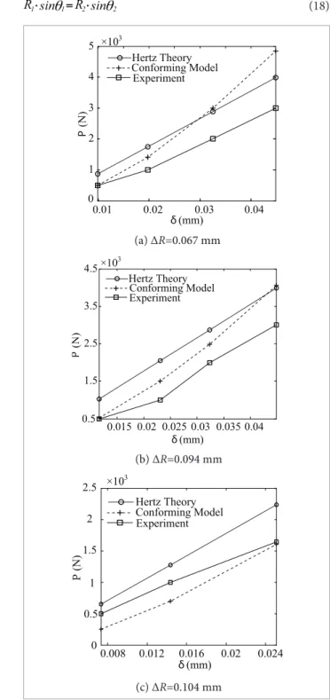
The experiment, which is shown in Fig. 2, is set up to evaluate the accuracy of nonconformal model and conformal model in calculating the stiffness of revolute joint. The joint was fixed between the base and the moving beam. The moving beam moved in the vertical direction. So the load applied on the joint was also in the vertical direction. The displacement of the moving beam and force along the joint can be collected by encoder and sensor, which correspond to the variable δ and P. The Young’s modulus of revolute joint is 2.06×10⁵ MPa. The experiment introduces three joints with different radial clearances which are 0.067, 0.094, and 0.104 mm, respectively. The contact length is taken as one where P is the contact load under the per unit length of the
contact cylinder.
The contact load P can be expressed as (Johnson, 1985)
2
a E P
4R
=π (4)
Because a can be expressed by δ, as
a
=
δ
R
(5)where δ is the mutual approach of distant points on the pin and the hole of the tang.
So the contact load can be expressed by the contact depth
P E
4 =
π
δ
(6)
In Hertz laws (Johnson, 1985), three assumptions need to be satisfied: surfaces are continuous, nonconforming, and frictionless; the strain is small; each solid could be considered as an elastic half-space. However, the contact pair of revolute joints with clearance has conformal surfaces that cannot satisfy the assumption of Hertz theory. So the conformal model must be considered.
Conformal contact model
In the previous part, the nonconformal contact model is expressed to calculate the contact force and penetration depth. Because the clearance in revolute joint is small, the contact of revolute joint is conformal contact. The normal contact of conformal surfaces has also been considered by Steuermann and Persson (Johnson, 1985). The profiles are represented as a polynomial to achieve a required degree approximation. So the initial separation of the contact bodies’ boundary can be expressed as
2 4 6 2n
1 2 3 n
h=A x +A x +A x + +... A x +... (7)
The external normal load and compression between centers of the contact bodies can be expressed as
(
)
(
)
2n 1 n n
4A Ena 2 4 2n
P
2n 1 1 3 2n 1
+ ⋅ ⋅⋅⋅
=
+ ⋅ ⋅⋅⋅ − (8)
(
)
δ= ⋅ ⋅⋅⋅
⋅ ⋅⋅⋅ − n
2 4 2n A a
1 3 2n 1 (9)
The second-order profiles assumed in this model is corresponding to n=1 in the Hertz theory. So the simplest initial separation in the revolute joint contact can be given by
2 1
h=A x (10)
The compression can be expressed as
2 1
2A a
δ= (11) Figure 2. Revolute joint experiment.
Joint Moving
Beam
Moving
Direction Base
unit length for the comparison of the experimental data with other model results, because the coaxially usually cannot be guaranteed in experiment. The comparisons of the joint deformation among nonconformal and conformal model results with experimental results demonstrate the suitability of the models, shown in Fig. 3.
As shown in Fig. 3, it is found that the results based on nonconformal model and conformal model are not close to the experimental results. The average errors of the two models are more than 50% and 30% separately. The nonconformal model results based on Hertz theory have large errors in small clearance and small errors in large clearance. However, conformal model is closer to the experiment results compared with Hertz model when the clearance is small. Because the Hertz model is base on nonconformal contact, it is more applicable to large clearance contact. The conformal model is more suitable for small clearance contact.
NONLINEAR CONTACT MODEL BASED ON THE GEOMETRIC CONSTRAINT
In the previous comparison, it is obvious that Hertz theory cannot solve the contact of revolute joint with clearance exactly, which is based on the assumption of nonconformal contact and the simplest conformal equation. So the dynamics simulation of multibody system cannot be performed conveniently and accurately. A new contact model is proposed in this section and is proved by comparing with above models.
Geometric constraints
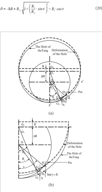
To find the relationship between the contact depth and the width, the new model must satisfy the geometric constraint. Based on the model of Fig. 1, the contact deformation and other assistant parameters are shown in Fig. 4.
The coordinates of the points G1 and G2 in the border of the pin and hole can be written as:
1 1
1 1
x
R
y
R
θ
θ
⎧⎪ ⎨ ⎪⎩
=
=
.
.
sin
11
cos
(15)2 2
2 2
x R
y R R
θ
θ
⎧⎪ ⎨ ⎪⎩
=
Δ +
.
.
sin 2
cos 2 (16)
where θ
1 and θ2are the center angles of the G1 and G2.
0.01 0.02 0.03 0.04
0 1 2 3 4 5 ×10
3
Hertz Theory Conforming Model Experiment
P
(N
)
δ (mm)
(a) ΔR=0.067 mm
0.015 0.02 0.025 0.03 0.035 0.04 0.5
1.5 2.5 3.5 4.5
Hertz Theory Conforming Model Experiment
P
(N
)
δ (mm)
×103
(b) ΔR=0.094 mm
0.008 0.012 0.016 0.02 0.024
0 0.5 1 1.5 2
2.5 ×10
3
Hertz Theory Conforming Model Experiment
δ (mm)
P
(N
)
(c) ΔR=0.104 mm
Figure 3. The results of the models and experiment.
Based on Eqs. 15 and 16, the distance of points having the same x coordinate separately in different circles can be written as
θ θ
= Δ + 2 −2 1 1
hhh= Δ +- R= Δ +- R- RRR.2R. −2cos. cosθ2 RR1..cos (17)
Because the two points G1 and G2 have the same x coordinate, θ
1 and θ2satisfy
=
.R1 s i n 1 R .s i n
Based on the relationship of contact width with pin radius and contact semiangle a=R1.sinε which is shown in Fig. 4, Eq. 20 can be expressed as
2 2 2 2
2 1
R R a R a
δ= −Δ + − − − (21)
Eq. 21 can also be expressed as
(
)
(
2 2 2 2)
2 22 1 2 1
R R a R a =R −R
+ Δ − + −
δ (22)
So
(
)
2 2
2 2 2 2 2 1
2 1
R R
R a R a
R δ
− = − + −
+ Δ (23)
By adding the Eq. 23 to Eq. 21, R12−a2can be eliminated. The contact width a can be given by
= − + +∆
4 R
2 2 2
2 2 1 2
1 R R
a R
δ
R
δ
+ ∆− (24)Approximate model for revolute joint with clearance The difficulty of establishing the contact model of revolute joints with clearance is how to determine the distribution of contact pressure and stress in the contact body when the geometry constraint is satisfied. In this article, the research is limited to the case that deformations of contact bodies are elastic and there is no friction. Based on the assumptions that: the shape of the contact area of the pin and role satisfies the geometric constraint given by Eq. 24; based on the half-space theory, the inner stress distribution of contact bodies has been considered; the contact pressure is assumed as ellipse distribution of Hertz theory. The deformation of the pin can be given by (Johnson, 1985)
2
1
b 1
4R 1
2P
E a
ν
δ
− =
π 2 ln (25)
Because the clevis and tang contact with pin at relative direction, the total deformation of contact pair of clevis and pin is
δ=2δb (26)
Substituting Eq. 21 into Eq. 26, the contact load on per unit length of cylinder can be expressed as
(
)
(
(
)
)
2 2 2 2
2 1
2
1
R R a R a
E P
2 ln 4R / a 1
4
ν
−Δ + − − −
=
− −
1
π
(27)
The relationship of contact depth and force can be expressed by
Considering Eq. (18) and trigonometric relationship
2 2
1
sin q2 +cos q2= , h in Eq. (17) can be redefined into
θ = ∆ + − −. θ . θ
2
1
1 2 1 1 1
2
R R
. .
2
1
2
R
R (19)
When θ
1 is equal to contact semiangle ε, h(θ1) corresponds to the distance of the edge points H1 and H2. Due to the deformation of the hole of the tang and the pin, the total displacement of the tang is equal to δ and h(ε), which can be found in Fig. 4. Based on Eq. 19, δ can be written as
. 2 .
1 2
R
R (20)
Figure 4. The geometry model of revolute joint with
clearance: (a) integral geometry model and (b) A quarter of the geometry model.
(a)
(b)
ΔR O
h
x+
y+
G1
G2
θ1 θ2
O1
O2
Pin The Hole of
theTang Deformation of the Hole
δ
H1
H2
δ
O O 1
h
G1
G2 θ
1
θ
2
Pin The Hole of
theTang Deformation
of the Hole δ
( )
h e =δ O2
H1
H2 R
∆
Figure 6 shows the penetration depth of simplest conformal and nonconformal contact when the radial clearance is 0.067 mm. It is clearly shown that the nonconformal and simplest conformal contact depth cannot be very large, because the contact depth has linear relationship with the square of contact width. The maximum displacement increases rapidly in the new model when the contact width is close to the radius of the surface. However, the penetration depth of conformal model and corresponding Hertz model always rise steadily with the contact width increase and is hard to reach a large value when the contact width approaches to the radius of the contact surface.
CONCLUSIONS AND FUTURE
WORKS
This article investigates the conformal contact model of revolute joint with clearance. The revolute joint experiment is conducted to evaluate the nonconformal and the simplest polynomial fitting conformal model. By comparing the two models with experimental results, it
(
)
1 2
2 2
2 2 1
1 2
2 1
E 1 R -R
P 2ln 4R / R - + + R
-4 + R 4
δ
δ
δ
ν
−
⎛ ⎞
⎜ ⎟
⎜ ⎟
⎝ ⎠
⎛ ⎛ ⎞ ⎞
⎜ ⎜ ⎟ ⎟
⎜ ⎟
⎜ ⎝ ⎠ ⎟
⎝ ⎠
= Δ
Δ
1
-π
(28)
Comparisons of three models and experiment for revolute joints with clearance
To verify the new contact model for revolute joint, the comparisons among the Hertz model, conformal model, and new model (experiment) are conducted. The results are presented in Table 1. The normal load P versus the normal displacement δ curve is shown in Fig. 5 which is obtained from the Hertz model given by Eq. 6, new model expressed by Eq. 28, simplest conformal model written as Eq. 14, and experimental data.
Observed from Fig. 5, it is found that the new contact model is closer to the experimental results than Hertz model and conformal model. The error of Hertz model decreases with the increase of the clearance. The errors of simplified conformal model and new model are small compared with Hertz model when the clearance is small. Because the contact of clearance revolute joint is close to conformal contact, the new model is more suitable for calculating the contact of revolute joint.
Table 1. The comparison of the Hertz and conformal model with experimental results.
∆R (mm) δ (×10–2mm)
Experiment Hertz theory Conformal model
p -value (N) p -value (N) Relative error (%) p -value (N) Relative error (%)
0.067
0.981 500 871 74.20 494 -1.20
1.971 1000 1751 75.10 1410 41.00
3.253 2000 2889 44.45 2988 49.40
4.484 3000 3983 32.77 4836 61.20
0.094
1.156 500 1026 105.20 527 5.40
2.308 1000 2054 105.40 1502 50.20
3.232 2000 2871 43.55 2483 24.15
4.484 3000 3983 32.77 4056 35.20
0.104
0.734 500 653 30.60 252 -49.60
1.436 1000 1275 27.50 696 -30.40
is found that the Hertz model is just suitable to solve the revolute joint contact when the contact load is not very large. The stiffness calculated by the simplest conformal model is higher than the nonconformal model and it is more accurate when the clearance is not small. The new model is built to solve the conformal contact problem which is based on geometric restriction, the half space theory, pressure distribution of Hertz theory, elastic deformation, and frictionless. When the clearance is large, the errors of conformal model and new model are close to each other by comparing these models with experiment. The error of new model is the smallest when the clearance is not very large. And it has not changed rapidly with the increase of clearance. So the new model is more simple and reliable to calculate the contact of revolute joint.
Future work focuses on the dynamic characteristics of the revolute joints. The friction and damping will be considered. The corresponding dynamic experiment will be conducted to get the dynamic characteristic.
ACKNOWLEDGMENTS
The authors acknowledge the support from the Natural Science Foundation of China (Project No. 50935002&11002039).
0.00981 0.01971 0.03253 0.04484 -10
0 10 20 30 40 50 60 70 80
R
el
at
iv
e
E
rr
o
r
o
f
P
(
%
)
δ (mm)
Hertz Theory
New Model Conformal Model
(a) ΔR=0.067 mm
0 20 40 60 80 100 120
0.01156 0.02308 0.03232 0.04484
R
el
at
iv
e
E
rr
o
r
o
f
P
(
%
)
δ (mm)
Hertz Theory
New Model Conformal Model
(b) ΔR=0.094mm
Hertz Theory
New Model Conformal Model
δ (mm)
- 50 - 40 - 30 - 20 - 10 0 10 20 30 40
0.00734 0.01436 0.02512
R
el
at
iv
e
E
rr
o
r o
f
P
(
%
)
(c) ΔR=0.104mm
Figure 5. Relation of the normal force and the total contact
depth.
Figure 6. Relation of the contact width and the penetration
depth.
0.5 1 1.5 2 2.5
0 0.1 0.2 0.3 0.4 0.5 0.6 0.7 0.8
0.9 Hertz Theory New Model
a/mm
δ
/m
REFERENCES
Abdo, J. and Shamseldin, E., 2005, “Modeling of Contact Area, Contact Force, and Contact Stiffness of Mechanical Systems with Friction”, 2005 ASME International Mechanical Engineering Congress and Exposition, Orlando, pp. 1-8.
Bengisu, M.T., Hidayetoglu, T. and Akay A., 1986, “A Theoretical and Experimental Investigation of Contact Loss in the Clearances of a Four-Bar Mechanism”, ASME, Vol. 108, pp. 237-244.
Dubowsky, S. and Freudenstein, F., 1971, “Dynamic analysis of mechanical systems with clearances, Part 1: Formulation of dynamic model”, Journal of Engineering for Industry, Vol. 93, pp. 305-309.
Erkaya, S. and Uzmay, I., “Effects of balancing and link lexibility on dynamics of a planar mechanism having joint clearance”, Sharif University of Technology Scientia Iranica, doi: 10.1016/j. scient.2012.04.011.
Flores, P. and Ambreósio, J., 2004, “Revolute joints with clearance in multibody systems”, Computers and Structures, Vol. 82, pp. 1359-1369.
Flores, P., Ambrósio, J., Claro, J. C. P. and Lankarani, H. M, 2006a, “Dynamics of Multibody Systems with Spherical Clearance Joints”, Transactions of the ASME, Vol. 1, pp. 240-247.
Flores, P., Ambrósio, J., Claro, J.C.P., Lankarani, H.M. and Koshy, C.S., 2006b, “A Study on Dynamics of Mechanical Systems Including Joints with Clearance and Lubrication”, Mechanisms and Machine Theory, Vol. 41, pp. 247-261.
Flores, P., Leine, R. and Glocker. C., 2010, “Modeling and Analysis of Planar Rigid Multibody Systems with Translational Clearance Joints Based on the Non-smooth Dynamics Approach”, Multibody System Dynamics, Vol. 23, pp. 165-190.
Ingham, M.D. and Crawley E.F., 2001, “Micro Dynamic Characterization of Modal Parameters for a Deployable Space Structure”, AIAA, Vol. 39, pp. 331-338.
Jia, X., Jin, D., Ji, L. and Zhang, J., 2002, “Investigation on the Dynamic Performance of the Tripod-ball Sliding Joint with Clearance in a Crank-sliding Mechanism. Part 1. Theoretical and Experimental Results”, Journal of Sound and Vibration, Vol. 252, pp. 919-933.
Johnson, K.L., 1985, “Contact Mechanics”, Cambridge University Press, Cambridge, 99 p.
Khemili, I. and Romdhane, L., 2008, “Dynamic analysis of a lexible slider-crank mechanism with clearance”, European Journal of Mechanics A/Solids, Vol. 27, pp. 882-898.
Knight, M.G., de Lacerda, L.A., Wrobel, L.C. and Henshall, J.L., 2002, “Parametric Study of the Contact Stresses Around Spherical and Cylindrical Inclusions”, Computational Materials Science, Vol. 25, pp. 115-121.
Lake, M.S. and Lee, D., 1996, “A revolute joint with linear load-displacement response for precision deployable structures”, The 37th
AIAA/ASME/ASCE/AHS/ASC Structures, Structural Dynamics, and Materials Conference, Salt Lake City, pp. 1-14.
Lankarani, H.M. and Nikravesh, P.E., 1990, “A contact force model with hysteresis damping for impact analysis of multibody systems”. Journal of Mechanical Design, Vol. 112, pp. 369-376.
Larsen, J.J., Jenkins, C., Banik, J. and Murphey, T., 2009, “Continuum Structural Representation of Flexure and Tension Stiffened 1D Spacecraft Architectures”, 50th AIAA/ASME/ASCE/AHS/ ASC Structures, Structural Dynamics, and Materials Conference, California, pp. 1-13.
Liu, C.S., Yang, L. and Zhang, K., 2006, “Normal Force-Displacement Relationship of Spherical Joints with Clearances”, Transactions of the ASME, Vol. 1, pp. 160-167.
Meguro, A., Shintate, K., Usui, M and A. Tsujihata., 2009, “In-orbit Deployment Characteristics of Large Deployable Antenna Relector Onboard Engineering Test Satellite VIII”, Acta Astronautica, Vol. 65, pp. 1306-1316.
Olyaei, A.A. and Ghazavi, M.R., 2012, “Stabilizing slider-crank mechanism with clearance joints”, Mechanism and Machine Theory, Vol. 53, pp. 17-29.
Parenti-Castelli, V. and Venanzi, S., 2005, “Clearance Inluence Analysis on Mechanisms”, Mechanism and Machine Theory, Vol. 40, pp. 1316-1329.
Qi Z.H., Xu, Y., Luo, X. and Yao, S., 2010, “Recursive Formulations for Multibody Systems with Frictional Joints Based on the Interaction Between Bodies”, Multibody System Dynamics, Vol. 24, pp. 133-166.
Ravn, P., 1998, “Continuous Analysis Method for Planar Multibody Systems with Joint Clearance”. Multibody System Dynamics, Vol. 2, pp. 1-24.
Rhee, J. and Akay, A., 1996, “Dynamic response of a revolute joint with clearance”, Mechanisms and Machine Theory, Vol. 31, pp. 121-134.
Schwab, A.L., Meijaard, J.P. and Meijers, P., 2002, “A Comparison of Revolute Joint Clearance Models in the Dynamic Analysis of Rigid and Elastic Mechanical Systems”, Mechanism and Machine Theory, Vol. 37, pp. 895-913.
Shi, B. and Jin, Y., 2008, “Dynamic analysis of the reheat-stop-valve mechanism with revolute joint in consideration of thermal effect”, Mechanism and Machine Theory, Vol. 43, pp. 1625-1638.
Tian, Q., Zhang, Y., Chen, L. and Flores, P., 2009, “Dynamics of spatial lexible multibody systems with clearance and lubricated spherical joints”, Computers and Structures, Vol. 87, pp. 913-929.