RESONANCE CONTROL OF PIEZOLAMINATED STRUCTURES
José M. Simões Moitaa, Cristóvão M. Mota Soaresb,*, Carlos A. Mota Soaresb
a
Universidade do Algarve, Escola Superior de Tecnologia, Faro, Portugal b
IDMEC/IST–Instituto Superior Técnico, Lisboa, Portugal,
Abstract
This paper deals with a third order shear deformation finite element model which is applied on the active resonance control of thin plate/shell laminated structures with integrated piezoelectric layers or patches, acting as sensors and actuators. The finite element model is a single layer triangular nonconforming plate/shell element with 24 degrees of freedom for the generalized displacements, and one electrical potential degree of freedom for each piezoelectric element layer, which are surface bonded on the laminate.
The Newmark method is considered to calculate the dynamic response of the laminated structures, forced to vibrate in the first natural frequency. To achieve a mechanism of active control of the structure dynamic response, a feedback control algorithm is used, coupling the sensor and active piezoelectric layers. The model is applied to the solution of one illustrative case, and the results are presented and discussed.
Keywords: High Order Theory, Laminated Structures, Sensors and Actuators. Dynamic Control.
1. Introduction
Advanced reinforced composite structures incorporating piezoelectric sensors and actuators are increasingly becoming important due to the development of smart structures. These structures offer potential benefits in a wide range of engineering applications such as vibration and noise suppression, shape control and precision positioning.
Using a higher order shear deformation theory, Samanta et al. [1] developed an eight-noded finite element for the active vibration control of laminated plates with piezoelectric layers acting as distributed sensors and actuators. The active control capability is studied using a simple algorithm with negative velocity feedback. Lam et al. [2] and Moita et al. [3] developed a finite element model based on the classical laminated theory for the active control of composite plates containing piezoelectric sensors and actuators.
In the development of the present work a higher order displacement field is used, which allows to taken into account transverse shear stresses and does not need the use of shear correction factors. The model is suitable for the analysis of highly anisotropic structures ranging from high to low length-to-thickness ratios. This approach leads to better displacements results when compared to classical Kirchoff or even first order shear deformation theories based models [4]. The finite element used is a flat three-noded triangular element with 24 mechanical degrees of freedom and one electric degree of freedom per piezoelectric layer of the finite element. * Corresponding author
An integrated control is considered, with the electrical potential of the sensors being used through feedback control as electric potential input of the actuators, in order to achieve an active damping mechanism. The governing equations are solved by the Newmark method [5] which is a direct method for time integration.
2. Displacement and Strain Fields
The assumed displacement field, for the numerical higher order finite element model, is a third order expansion in the thickness coordinate for the in-plane displacements and a constant transverse displacement, conjugated with the condition that the transverse shear stresses vanish on the top and bottom faces, which is equivalent to the requirement that the corresponding strains be zero on these surfaces [4].
(
)
( )
( )
( )
x w y , x 3h 4 z y , x z y , x u z , y , x u 0 y 3 2 y 0 ∂ ∂ − θ + θ − =(
)
( )
( )
( )
∂ ∂ − θ − + θ + = y w y , x 3h 4 z y , x z y , x v z , y , x v 0 x 3 2 x 0 (1)(
x,y,z)
w( )
x,y w = 0where u0, v0, w0 are displacements of a generic point in the middle plane of the laminate
referred to the local axes - x,y,z directions, θ θx, y are the rotations of the normal to the middle plane, about the x axis (clockwise) and y axis (anticlockwise), ∂w0 ∂x, ∂w0 ∂y are the slopes of the tangents of the deformed mid-surface in x,y directions,θz is the rotation about the local z axis, which does not enter in the formulation in the local coordinate system.
The strains components associated with the displacements are given in Moita et al [6].
3. Piezoelectric Laminates. Constitutive Equations.
Assuming that a piezoelectric composite plate consists of several layers, including the piezoelectric layers, the constitutive equation for a deformable piezoelectric material, coupling the elastic and the electric fields are given by, Tiersten [7]
E e Qε σ= − (2) E p e D= T ε + (3) where σ =
{
σx σy σxy τxz τyz}
T and ε ={
εx εy γxy γxz γyz}
T are the elastic the stress and strain vectors, Q the elastic constitutive matrix, e the piezoelectric stress coefficients matrix, E =[
Ex Ey Ez]
Tthe electric field vector, D=[
Dx Dy Dz]
T the electric displacement vector and p the dielectric matrix, in the element local system (x,y,z) of the laminate. The ij p , ij e , ijQ are functions of ply angle α for the kth layer, and are given for the
The electric field vector is the negative gradient of the electric potential φ, which is assumed to be applied and varying linearly in the thickness t direction, i.e. k
φ −∇ =
E ; E=
{
0 0 Ez}
T ; Ez =−φ/tk (4)4. Finite Element Formulation.
The non-conforming high order triangular finite element model (HSDT) has three nodes and eight degrees of freedom per node, the displacements
i i i 0 0 0 , v , w u , the slopes y w , x w0 ∂ ∂ 0 ∂
∂ , and rotations θxi ,θyi ,θzi. By neglecting the transverse shear deformation, a Kirchhoff laminated finite element model with 6 degrees of freedom per node (CPT) is also easily obtained. The element local displacements , slopes and rotations are expressed in terms of nodal variables through shape functions N given in terms of area co-ordinates i L [8]. Thus i the displacement and strain fields are given as in Moita et al [6], and the electric field is given by:
φ − = Bφ
E (5) The dynamic equations of a laminated composite plate can be derived from the Hamilton’s principle, which, in the discretized form, is given as follows
)
{ }
a dA{ }
a dS{ }
a dS dt 0 dA ) dz ( dA dz a 0 0 0 0 a S S c T V T h h T n 1 = k k A T t t N 1 K A mec T T mec T h h T T T k 1 -k 2 1 k 1 -k = ∫ δ +δ +∫ δφ + ∫ δ + ∫ ∑ ρ ∫ ∫ ∑ ∫ − φ − φ ∫ δ = φ φ Q F t N f N N Z N p e e Q B B B B (6)leading to the following sistem of equations
= φ + φ φφ φ φ ) t ( F (t) F K K K K 0 0 0 M ele mec ext u u uu uu q q & & & & (7) where dA dz B Q B K N mecT mec 1 = K A h h uu k 1 -k ∑ ∫ ∫ = K N BmecT e B dz dA 1 = K A h h u k 1 -k φ φ = ∑ ∫ ∫ dA dz B e B K N T T mec 1 = K A h h u k 1 -k φ φ = ∑ ∫ ∫ K B p B dz dA T N 1 = K A h h k 1 -k φ φ φφ =− ∑ ∫ ∫ (8)
Assuming that piezoelectric sensors as well as actuators are bonded or embedded in the structure, the electric potential vector is subdivided in a sensor component φ( )S and an actuator component φ( )A . Separating actuator and sensor components and considering that the external applied electric charge at the sensors is zero the system of Eq. (7) takes the form
[
Muu]{ } [
q&& + Kuu]{ }
q +[ ]
K(uSφ){ }
φ(S) ={
Fextmec(t)−K(uAφ) φ(A)}
(9)[ ]
Kφ(A)u{ }
q +[ ]
K(A)φφ{ } {
φ( )A = Fele(t)}
(10)[ ]
Kφ(S)u{ }
q +[ ]
Kφφ(S){ }
φ( )S ={ }
0 (11)4. Dynamic Analysis
The sensor output can be obtained as follows, Reddy [9]. The charge output of each sensor, with poling in the z direction, can be expressed in terms of spatial integration of the electric displacement over its surface, taking into account that the converse piezoelectric effect is negligible. Thus we have
∫ + ∫ = ∫ = + = = dA ) t ( D dA ) t ( D 2 1 dA ) t ( D ) t ( Q ) z z ( A z ) z z ( A z A z ) S ( 1 k k (12)
From Eq. (3), the last equation can be written in the discretized form as follows
{ }
q[ ]
K{ }
q dA) B e ( ) t ( Q (S)u A mb T ) S ( φ = ∫ = (13) The current on the surface of the sensor is given by I(t)=dQ(S) dt and can be converted into the open circuit sensor voltage output φ(S)as φ(S) =GcdQ(S) dt where G is the constant c gain of the amplifier, which transforms the sensor current to voltage. The sensor output voltage can be feed back through an amplifier to the actuator with a change of polarity. Thus, we have for the actuator voltage φ(A) =−GiGcdQ(S) dt where G is the gain of the amplifier to i provide feedback control. The voltage of each actuator, written in the discretized form, is then given by[ ]
K{ }
q G Gi c (S)u ) A ( & φ − = φ (14)This way we introduce an equivalent negative velocity feedback control, the active damping. Considering Rayleigh type damping the motion equations become:
[
Muu]{ } (
q CR CA){ }
q[ ]
Kuu[ ][ ] [ ]
K(uS) K(S) 1 K(Su) { }
q ={
Fextmec(t)}
− + + + & φ φφ − φ & & (15)with CA =−GiGc
[ ][ ]
K(uAφ) Kφ(S)u andCR =αMuu +βKuu, where α and β are Rayleigh’s coefficients.5. Vibration control of a cantilever beam under sinusoidal loading.
A cantilever graphite-epoxy composite beam
[
a/0º/90º/90º/0º/s]
made up of four-layer, equal thickness, symmetric cross-ply and two PVDF layers bonded to the upper (actuator a) and lower (sensor s) surfaces of the main structure, is considered. The mechanical and piezoelectric properties of the PVDF are E1=E2=2 GPa, G12=0.775 GPa,GPa 775 . 0 G G13= 23= , ν12 =0.29, p33 =1.062 x 10⁻¹⁰F/m,e31= e32 = 0.046C/m2, ρ=1800 kg/m3, and mechanical properties of the graphite-epoxy are
, GPa 98
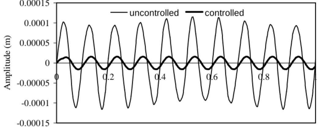
E1 = E2=7.9GPa,G12 =5.6GPa,G13 =G23 =4.72GPa ν12=0.28, ρ=1520 kg/m3, t=0.125x10⁻³ m. The applied transverse harmonic load q(t)=q sin 2πf t, is a uniformly distributed load and has a magnitude of q=7.5N/m2. The beam dimension are length L=0.1 m and width b=0.005 m, and is modeled by 10 triangular elements. For an applied transverse harmonic load with f =10Hz, Figure 1 illustrates, the uncontrolled and controlled responses for tip deflection w for the first mode of vibration, where the effect of negative velocity feedback control GiGc =2.0x10¹², is evident.
-0.00015 -0.0001 -0.00005 0 0.00005 0.0001 0.00015 0 0.2 0.4 0.6 0.8 1 Time (seconds) A m p lit ud e (m) uncontrolled controlled
Figure 1. Effect of negative velocity feedback control on the tip deflection.
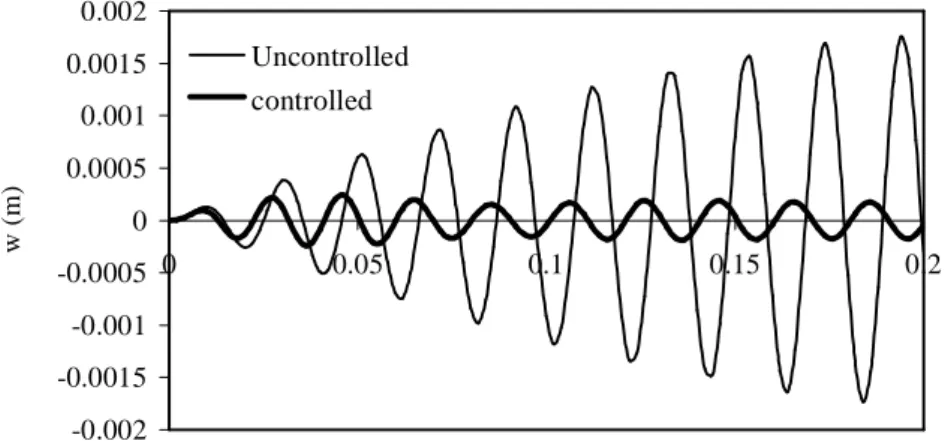
For an applied transverse harmonic load with f =50Hz, which is very close of the first natural frequency, a time step ∆t=0.002 s is used for the Newmark method. Using the HSDT present mode, Figure 2 illustrates the uncontrolled and controlled responses for tip deflection w, where the effect of negative velocity feedback control GiGc =2x10¹⁰ is now much more evident.
Conclusions
The active control capability of composite structures covered with piezoelectric layers is investigated, using the finite element method. A finite element model has been developed for active control of thin laminated structures with piezoelectric sensor and actuator layers, based
on the third order shear deformation theory. The results obtained show that the negative velocity feedback control algorithm used in this model is effective for an active damping control of vibration response.
-0.002 -0.0015 -0.001 -0.0005 0 0.0005 0.001 0.0015 0.002 0 0.05 0.1 0.15 0.2 Time (seconds) w (m) Uncontrolled controlled
Figure 2. Effect of negative velocity feedback control on the tip deflection at resonance frequency
Acknowledgments
The authors thank the partial financial support of FCT/POCTI/FEDER, FCT-Proj. POCTI/P/EME/12028/2001, Phase II, and POCTI/2001/EME/37559.
References
1. Samanta B, Ray MC, Bhattacharyya R. Finite element model for active control of intelligent structures. AIAA Journal 1996; 34 (9):1885-1893.
2. Lam KY, Peng XQ, Liu GR, Reddy JN. A finite element model for piezoelectric composite laminates. Smart Material Structures 1997; 6: 583-591.
3. Moita JS, Mota Soares CM, Mota Soares CA. Geometrically non-linear Analysis of composite structures with integrated piezoelectric sensors and actuators. Composite Structures 2002; 57(1- 4): 253-261.
4. Reddy JN. Mechanics of laminated composite plates. CRC Press, Boca Raton, New York, 1997.
5. Bathe KJ. Finite Element Procedures in Engineering Analysis. Prentice-Hall Inc, Englewood Cliffs, New Jersey, USA, 1982.
6. Moita JS, Barbosa JI, Mota Soares CM, Mota Soares CA. Sensitivity analysis and optimal design of geometrically non-linear laminated plates and shells. Computers and Structures 2000; 76: 407-420.
7. Tiersten HF. Linear Piezoelectric Plate Vibrations. New York: Plenum Press, 1969.
8. Zienckiewicz OC. The Finite Element Method in Engineering Sciences, McGraw-Hill, 3 rd, London, 1977.
9. Reddy JN. On laminate composite plates with integrated sensors and actuators. Engineering Structures 1999; 21: 568-593.