!" #$%! & ' & ( )
*
+ ,- . / # , 0
"1! 2#3 ! * 4 & 0& ( )
* 5
* 67 , .
4 8 ,# 4
%!!3#!!! 9 & 4& ( )
! "# $
$
The use of cutting fluid in milling operations causes increase of temperature variation on the tool and may cause decrease of tool life. However, sometimes its use is necessary due to possible deleterious influence the temperature increase may have on the workpiece. Therefore, it is important to make fluid less harmful for the tool. In this work, two alternatives were tried: the application of emulsion internally to the tool, forcing it to get closer to the cutting edge and the use of an emulsion with higher concentration, trying to increase the lubrication and decrease the fluid cooling capacity. These alternatives were experimented in the face milling operation of stainless steel used in the aeronautic industry (where workpiece damage must be avoided) and were compared to the usual way of fluid application (externally to the tool and with lower concentration) and also to dry cutting, in two different cutting speeds. Tool wear damage was analyzed. The main conclusions were: a) dry cutting generated longer tool lives than cutting with emulsion no matter the way of application and the fluid concentration; b) tool wear mechanism which caused the end of tool life was attrition for dry cutting and cracks and chippings of thermal origin for cutting with emulsion, again, no matter the way of fluid application and the fluid concentration. Keywords: cutting fluid, milling, dry cutting, PH stainless steel, tool wear
Introduction
1
The costs related to the use of cutting fluid, which can reach up to 17% of the total manufacturing costs, the risks for the operator health and the growing rigidity of the ecological laws have forced industries to make their productions less and less dependant of cutting fluids. Several ways have been tried lately to reduce the inconvenient of cutting fluid use. One of them is the dry cutting, in which cutting fluid is eliminated from the process. Obviously, this solution takes out the process the cutting fluid benefits like tool lubrication and cooling and also chip removal from the cutting region. Therefore, the use of dry cutting must be analyzed in each specific situation. In milling processes, for instance, the use of water based cutting fluid, which has high cooling capacity but low lubrication capacity, increases the tool temperature variation in each tool revolution and, usually, contributes to the increase of cracks of thermal origin. In the other hand, some times the cutting fluid must be applied to the process to protect the workpiece from an excessive heating and, therefore, to avoid either metallurgical damages to the workpiece surface or deformation of workpiece thin walls. This work verifies whether the way of fluid application (internally or externally to the tool) and the emulsion concentration influences tool life and tool wear mechanism. Moreover, it also demonstrates the damages the use of abundant water based cutting fluid (vegetable emulsion) brings to the tool in the milling of precipitation hardened stainless steels (used in aeronautical industries) with carbide inserts. All the experiments were carried out in two different cutting speeds and their results were compared to the experiments using dry cutting.
Cutting Fluid Application in Continuous and Interrupted Machining Processes
In continuous machining processes like turning, lubrication is harmed, because it is difficult for the fluid to reach the chip-tool and workpiece-tool interfaces in order to decrease the friction coefficient. According to Kalpakjian (1991) the fluid is dragged inside the chip-tool interface using the capillarity effect caused by
Paper accepted February, 2008. Technical Editor: Fernando Antônio Forcellini.
the space produced by the tool surface roughness, what may have a lubricant effect. In order to penetrate in these small spaces, the fluid must have small molecules. According to Childs et al. (1988) and Seah et al. (1997) the contact pressure between tool and chip is very high what blocks all the possible ways for the fluid penetration in the tool-chip contact region. What occurs in most of cases is and indirect cooling, since the fluid removes heat from the chip surface, from the workpiece and from the tool exposed to the contact with it. Trent and Wright (2000) affirmed that in areas of seizure between chip and tool there is no possible access of externally applied lubricants to most of the interface. Therefore, just in the periphery of the contact between chip and tool, where sliding occurs, the fluid penetration is possible.
Then, in continuous cutting cooling must be the main goal of fluid application, instead of lubrication and, therefore, the use of water based cutting fluids usually brings benefits to the process. Diniz and Micaroni (2002) carried out several experiments in different cutting conditions (typical of finish turning), using water based cutting fluid in turning process of AISI 1045 steel with coated carbide tool. In all cutting conditions tool lives obtained in the experiments with abundant cutting fluid were compared with those obtained with dry cutting. Their main conclusions were: a) the abundant cutting fluid provided longer tool lives than dry cutting in all cutting conditions tried; b) in order to make tool life obtained with dry cutting closer to that obtained with abundant cutting fluid, it is necessary to decrease cutting speed, increase feed and tool nose radius.
In the other hand, lubrication is facilitated in milling operations, since when the cutting edge is rotating in the air in each revolution and receives a certain amount of fluid with high lubrication capacity, it is able to bring this fluid to the interfaces chip-tool and tool-workpiece in order to perform the lubrication action. Therefore, it would be interesting to use neat oil in this kind of process. But, neat oil has its disadvantages. Among them, it can be cited that it is more expensive than the water based fluid and the smoke produced by it spreads in the air surrounding the machine and may cause health problems to the people who work in this environment (Salles et all., 2000). Other alternatives may be the use of a high concentrated water based fluid, with smaller cooling capacity and higher lubrication capacity and to apply the fluid internally to the tool, in an attempt to to reach the chip-tool and workpiece-tool interfaces. These alternatives are going to be experimented in this work.
The workpiece material used in the experiments of this work was the 15-5PH stainless steel. This material has a broad use in the aeronautic industry. In this kind of industry it is usual to perform all the machining operations with abundant cutting fluid, in order to avoid any metallurgical damage to the workpiece, even with the consequent decrease of tool life. This is another reason to try alternatives to the usual way of applying water based cutting fluid which is the application of a low concentration emulsion externally to the tool. The goal is to have a cutting fluid with higher lubrication capacity applied closer to the interfaces, in order to keep tool life similar to that obtained in dry cutting, without heating the workpiece so much.
This work verifies whether the way of fluid application (internal or externally to the tool) and the emulsion concentration influence tool life and tool wear mechanism. Moreover, it also demonstrates the damages the use of abundant water based cutting fluid
(vegetable emulsion) brings to the tool in the milling of precipitation hardened stainless steels (used in aeronautical industries) with carbide inserts. All the experiments were carried out in two different cutting speeds and their results were compared to the experiments using dry cutting.
Materials, Equipments and Methods
The workpiece material used in the experiments was the 15-5 precipitation hardened martensitic stainless steel with hardness of 31 ± 1 HRc. The workpiece dimensions were 355 mm of length x 205 mm of width x 75 mm of height.
The tool used in the experiments was an end mill with indexable inserts with 19.05 mm of diameter and 2 cutting edges. The cemented carbide inserts (ISO grade M20–M40) had as substrate WC plus Co and were coated with TiAlN (deposited by PVD process – Physical Deposition Vapor). The tool nose radius was 0.4 mm.
The experiments were carried out in a CNC vertical machining center, with available power in the spindle of 22 kW.
Tool flank wear was measured several times during the experiments using a stereoscope microscope (with maximum magnification of 50 times) connected to an image acquisition system composed of CCD camera and a computer with an image acquisition software.
Aiming to explain the tool wear behaviour, after the end of the experiments pictures of the worn tools were taken in a Scanning Electron Microscope (SEM). In the same microscope, Energy Disperse Spectroscope (EDS) analysis were carried out.
All the experiments were carried out using down milling with passes executed in the longitudinal direction of the workpiece. After 5 consecutive milling passes, tool flank wear was measured. This measurement was made in each one of the three cutting edges. After the wear measurement, the tool was assembled again in the
machine-tool for the milling of a new set of passes. This procedure was repeated up to the point the tool reached its criterion of tool life (maximum flank wear VBmax = 0.2 mm).
The cutting fluid, when used, was a flood of vegetable oil based emulsion. Two concentrations of the emulsion were used (7 and 12%) with two different ways of fluid application (internally and externally to the tool). The cutting fluid flow rate was 45 l/min when applied externally and 22,5 l/min when applied internally to the tool (with high pressure – 70 bars). The results of these experiments were compared to the results of dry cutting experiments. Moreover, two different cutting speeds were used: vc = 120 and 140 m/min.
Each experiment was carried out twice. The order of the experiments was randomly chosen.
The performance of the cooling/lubrication condition was evaluated through the tool life obtained under each condition.
The parameters kept constant in all experiments were: radial depth of cut – 13.33 mm (70% of the diameter of the mill); axial depth of cut – 4 mm and feed per tooth – 0.12 mm.
Results and Discussions
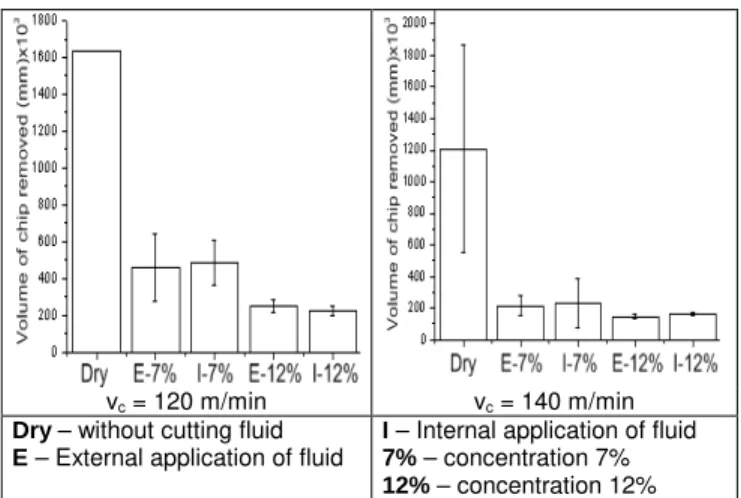
Figure 1 shows tool lives (in volume of chip removed) for all experiments carried out.
vc = 120 m/min vc = 140 m/min
Dry – without cutting fluid
E – External application of fluid
I – Internal application of fluid
7% – concentration 7%
12% – concentration 12%
Figure 1. Tool lives for all the experiments.
variation caused by the fluid application, since the cutting edge left the cut with a higher temperature in each revolution.
In order to carry out an analysis of the reasons which generated this tool life behaviour, pictures of the worn tools taken in a Scanning Electronic Microscope together with EDS results from the tool worn land in each condition will be shown next.
Figure 2 shows pictures of one of the inserts used in the experiment with vc = 140 m/min and dry cutting.
(a) General view of one of the cutter worn cutting edges
(b) Magnified view of the marked region in picture (a) Chemical Elements in weight (%) Element W Co Cr Fe Ni Al Ti EDS 0.82 2.40 16.00 76.82 3.90 0.07 0.00
c) EDS analisys of the region marked on picture (b).
Figure 2. Pictures of the worn cutting edge and EDS analysis results, vc =
140 m/min, dry cutting.
As can be seen in this figure, the flank wear value was constant along the whole edge, but increased a lot in the region of the end of depth of cut. Figure 2b shows an amplified view of this region and figure 2c shows the results of the EDS analysis on this region. This analysis shows that the presence of a high level of elements from the workpiece (Cr, Fe and Ni, with more than 96% in weight) covered all the tool substrate on that point. Other points of the tool flank face also had the presence of elements from the workpiece, but not in such amount as that found in the end of the depth of cut. The presence of workpiece material on the tool flank face points out that the chip was extruded between workpiece and cutting edge due to the high normal pressure and the high ductility of the stainless steel. This extrusion was stimulated by the fact that the cutting edge radius was 45 µm and the feed per tooh was 120 µm which generated, for the tool diameter and axial depth of cut used, an average chip thickness of 85 µm. Therefore, a great portion of the chip was generated on the edge radius region, which presents a very negative rake angle, what increase even more the normal pressure. Adding to this the fact that the workpiece material is very ductile and it is in
high temperature due to the dry cutting, all the conditions are suitable for the extrusion of the chip through cutting edge and workpiece. This extruded material adhered to the flank face and caused the tool wear through the mechanism called by Trent (2004) as attrition. The adhered material was cyclically removed by the friction between tool and workpiece and, when removed, dragged tool particles.
The reason for the fact that the largest wear value occurred in the end of depth of cut region may be its stress condition, with very high stress in one side (the side involved in the cut) and without stress in the neighbour point (which is not involved in the cut). This stress condition made the region more sensitive to the removal of particles by attrition.
Figure 3 shows the pictures of the worn cutting tool edges used in the experiments with cutting speed of 120 m/min, emulsion application internally to the tool and emulsion concentration of 7%.
a) General view of insert 1
b) Magnification of region pointed in picture (a)
c) Magnification of the nose radius region of picture (a)
Figure 3. Pictures of the worn cutting edge and EDS analysis results. vc =
d) General view of insert 2
e) Magnification of the region pointed in picture (d)
f) Magnification of the region pointed in picture (e) Chemical elements in weight (%)
Element W Co Cr Fe Ni Al Ti EDS1 68.98 12.03 5.82 9.47 2.99 0.27 0.44
EDS2 4.29 2.14 5.58 21.65 1.18 10.33 54.83 g) EDS analysis of the regions pointed in figure (e)
Figure 3. (Continued).
The picture of the Fig. 3(a) shows a general view of insert 1 where it can be seen a large chipping in the region of the end of depth of cut. A magnification of this region shown on Fig. 3(b) shows a large crack. The picture of the Fig. 3(c) is a magnification of the nose radius region, where it can be seen scratches typical of abrasive wear (Trent and Wright, 2000) and, in the upper right side, some edge chippings. Along the edge abrasion occurred, especially on the workpiece material adhered, but what really limited tool life were the chippings in the end of the depth of cut produced by temperature variation, which initiate in the cutting edge. The picture of the Fig. 3(d) shows a general view of the flank face of insert 2 of the tool. It can be seen on this figure several cracks perpendicular to the cutting edge. Part of this face was magnified in the picture of
Fig. 3(e), where two cracks can be clearly seen. Moreover, a large chipping can be seen close to the crack at left. It can be observed that the chippings start around the cracks on the cutting edge. The crack at the right of the picture started on the cutting edge and propagated down to the flank face, as can be seen in Fig. 3(f). Comparing Fig. 3(a) and Fig. 3(d) it can be seen that the end of tool life was caused by the higher value of tool wear of insert 1, because in insert 2 the wear was much lower. This fact shows that in insert 1 the cracks propagate more quickly and, consequently, the chippings which originated the high tool wear value also increased fast.
Figure 3(g) shows the EDS analysis of the regions pointed in Fig. 3(e). In the whiter region close to the crack at right (EDS 1), mainly tool substrate material was found (81% of tungsten and cobalt), a lower amount of workpiece material adhered (18% of iron, chromium and nickel) and also a little of tool coating elements (0,71% of aluminum and titanium). In the dark region pointed as EDS 2 (border between worn and unworn regions) it can be seen a large amount of coating material (65% of aluminum and titanium), workpiece adhered material (28% of iron, chromium and nickel) and, in a lower amount, element from the tool carbide substrate (6,5% of cobalt and tungsten).
Therefore, it can be concluded that in this experiment (vc = 120 m/min, abundant emulsion), there was some wear caused by abrasion, but the main cause of flank wear was the presence of cracks and chippings generated by temperature variation. This temperature variation caused a large chipping in the end of depth of cut, which was the responsible for the end of tool life. Based on these analysis, this mechanism can be summarized:
• The cutting edge heats up when it is cutting during one revolution and cools down quickly, under the action of the emulsion, when it is not cutting in the same revolution. As the tool revolution was bigger than 2000 RPM for vc = 120 m/min, this temperature variation occurred more than 33 times per second.
• Due to these thermal shocks, a small crack appears on the cutting edge. This crack, as cutting time goes by, propagated down to the flank face.
• With the crack already present, the mechanical shocks inherent to the milling process, added to the continuation of the thermal shocks, made easier the appearance of chippings, close to the cracks.
• As cutting time goes by, the cracks and chippings increased both, in number and size.
• A moment is reached when the cracks and chippings get such proportion that a breakage of large volume of the cutting edge happens, making the continuation of the cutting dangerous, because the risk of a catastrophic failure of the insert is high.
• This phenomenon was more intense close to the end of the depth of cut due to the stress condition of that region, submitted to a large stress in the cutting side and no stress in the neighbour region, which is not involved in the cutting. Besides, the vicinity of this point involved in the cutting presents the temperature variation of the whole cutting edge, while the neighbour point outside the cutting is always wet by the cutting fluid and, so, remains in a lower temperature, without large variation.
It can be seen on Fig. 4(a) and Fig. 4(b) a large chipping in the end of depth of cut region. In the picture of the Fig. 4(c), which is a magnification of the region pointed on Fig. 4(b), it can be seen two cracks, one in the direction parallel to the cutting edge and the other in its perpendicular direction. The increase of cutting speed increases the heat input in the process and, due to the emulsion application, the thermal shock grows, making easier the crack generation. In this environment, the crack propagated faster and large flank wear values were reached earlier compared to what happened with cutting speed of 120 m/min, what shortened tool life.
a) General view of the insert
b) Magnification of the B region of picture (a)
c) Magnfication of the region pointed on picture (b)
Figure 4. Pictures of the worn cutting edge and EDS analysis results. vc =
140 m/min, emulsion application externally to the tool, 7% of concentration.
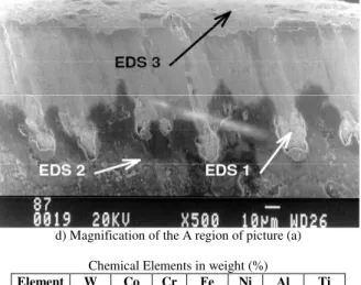
d) Magnification of the A region of picture (a) Chemical Elements in weight (%)
Element W Co Cr Fe Ni Al Ti
EDS1 79.84 9.51 2.40 4.63 0.63 0.81 2.18
EDS2 0.00 0.00 2.83 2.77 0.00 19.45 74.95
EDS3 62.41 14.59 6.79 14.40 1.38 0.42 0.00 e) EDS analysis of the regions pointed on figure (d)
Figure 4. (Continued).
In the picture of Fig. 4(d) and in the table of Fig. 4(e) (EDS analysis) it can be seen that in the region pointed as EDS 1 there was a large amount of tool substrate elements (W and Co) and, in a smaller amount, elements from the workpiece material (Fe, Cr and Ni) and tool coating (Ti and Al). It can also be seen (figures 4(a) and 4 (d)) that abrasion occurred along the tool flank wear land (point “A” in Fig. 4(a) which was magnified in Fig. 4(d)), since the scratches typical of abrasive process can be seen in these figures. The EDS 3 analysis of Fig. 4(e) shows some adhered workpiece material on the tool substrate, but no abrasive marks can be seen on it. In that region probably difusion was the mechanism which generated wear. The clues for this affirmation are that a small amount of workpiece material was present and the surface in that region is very smooth (Trent and Wright, 2000). The EDS 2 analysis presents just material from the tool coating (94% in weight of aluminium and titanium) with small amounts of material from the workpiece (less than 6% in weight of iron and chromium) and no element from the tool substrate. This region can not be considered a worn region anymore (it is in the vicinity of the wear land) and so the tool coating is almost intact. It is important to remember in this point that the picture on figure 4(d) shows the region of the cutting edge/flank face that did not present a large value of flank wear and, so, was not responsible for the end of tool life. Therefore, although present, abrasion and diffusion were not directly responsible for the end of tool life in this experiment.
Comparing Fig. 3 and Fig. 4 it can be seen that when cutting speed was increased from 120 to 140 m/min the wear rate increased but the wear mechanism was the same, i.e., cracks and chippings of thermal origin, which were more intense in the end of depth of cut region, causing the end of tool life. In other words, what determined the wear mechanism was the presence of the abundant emulsion and not the cutting speed. The increase of cutting speed just accelerated this mechanism.
Conclusions
Based in the results obtained in this work, it can be concluded for the milling of the precipitation hardened stainless steels with coated carbide inserts, in conditions similar to those used in the experiments of this work that:
of fluid application and the cutting speed. All the attempts of making fluid application less deleterious to the tool, like applying it internally to the tool and increase the fluid concentration did not work.
b) The higher the cutting speed, the larger is the difference between tool lives of dry cutting and cutting with abundant emulsion.
c) When dry cutting was used the end of tool life was caused by a large tool flank wear in the end of depth of cut region. The main mechanism which caused this large wear was attrition.
d) When cutting with abundant fluid was used also the end of tool life was caused by a large tool flank wear in the end of depth of cut region. However, in this situation the wear mechanism was different. Abrasion and diffusion were present along the cutting edge, but the mechanism which led the tool to its end of life was the cracks and chippings of thermal origin, which were present also on the whole cutting edge, but were more intense on the end of depth of cut region.
References
Childs, T. H. C.; Maekawa, K.; Maulik, P.; 1988, “Effects of coolant on temperature distribution in metal machining”, Materials Science and Technology, vol. 4, n. 11, pp.1006-1019.
De Melo, A. C. A.; Machado, A. R.; 2005, “Comparison of the wear development of ISO P45 tools coated with TiN/TiCN and ISO P25 without coating during face milling of AISI 1045 steel” (In Portuguese), 3th
Brazilian Congress of Fabrication Engineering – COBEF, de 12 a 15 de abril, Joinville, SC, Brazil, anals in CD.
Diniz, A. E.; Marcondes, F. C.; Coppini, N. L.; 2006, “Materials Machining Technology” (in Portuguese). São Paulo, Art Liber Editora, 256 p.
Diniz, A. E., Micaroni, R.; 2002, “Cutting conditions for finish turning process aiming: the use of dry cutting”, International Journal of Machine Tools & Manufacture, vol. 42, pp. 899-904.
Kalpakjian, S., 1991, “Manufacturing processes for engineering materials”, 2. ed., New York, Addison-Wesley.
Sales, W. F.; Diniz, A. E.; Machado, A. R., 2001, “Application of Cutting Fluids in Machining Processes”, Journal of the Brazilian Society of Mechanical Engineering, Rio de Janeiro, vol. XXIII, n. 2, pp. 227-240.
Seah, K. H. W.; Li, X.; 1997, “Influence of coolant on cutting tool performance”, Journal of Materials Science and Technology, vol. 13, n.3, pp. 199-205.