Improvements of Ultra-High Molecular Weight Polyethylene
Mechanical Properties by Nitrogen Plasma Immersion
Ion Implantation
A. R. Marcondes
1, M. Ueda
1, K. G. Kostov
1, A. F. Beloto
2, N. F. Leite
2,
G. F. Gomes
1, and C. M. Lepienski
31
Laborat´orio Associado de Plasma, Instituto de Pesquisas Espaciais (INPE)
S˜ao Jos´e dos Campos, C.P. 515, ZIP 12201-970, SP , Brazil
2
Laborat´orio Associado de Materiais e Sensores, Instituto de Pesquisas Espaciais (INPE) S˜ao Jos´e dos Campos, C.P. 515, ZIP 12201-970, SP , Brazil
3
Universidade Federal do Paran´a, Setor de Ciˆencias Exatas, Bloco II, Depto de F´ısica
Curitiba, C.P. 19044, ZIP 81531-990, PR, Brazil
Received on 29 January, 2004; revised version received on 7 May, 2004
Nitrogen Plasma Immersion Ion Implantation (PIII) has been used to modify the surface chemical structure of Ultra High Molecular Weight Polyethylene (UHMWPE). Grinding and polishing processes based on abrasive papers and alumina pastes have been evaluated with regard to their results on the improvement of polymer surface roughness, which has shown to be of crucial importance for hardness characterization. Raman spectros-copy, XPS, and Nanoindentation tests were used to characterize the modified surfaces. Experimental results has shown that UHMWPE surface mechanical properties such as hardness and elastic modulus can be improved by induced chain cross-linking between the macromolecules on the polymer surface caused by nitrogen PIII. The new material formed on the surface is Diamond Like Carbon (DLC). As a significant improvement in hard-ness was obtained by DLC synthesis on the treated surface, it is expected a dramatic improvement of abrasion resistance and overall durability of prostheses made with PIII treated UHMWPE.
1
Introduction
Total joint replacement has become an effective and popular surgical technique for restoring function to patients whose joint have been afflicted by major trauma or joint degenera-tive diseases. Millions of patients have been fitted with total joint prostheses over the past three decades. A majority of these prostheses have a metal surface articulating against a second component of ultra-high molecular weight polyethy-lene (UHMWPE). UHMWPE has evolved as the dominant material of choice in total joint prostheses because of its bio-compatibility, relative superior friction, wear characteristics, ductility and impact load damping.
The primary problem with UHMWPE in total hip joints is the constant generation of submicron particle debris that overwhelms the body’s ability to remove the material. The polyethylene wear particles generated at the articular sur-face have been recognized as a long-term cause of loosing and failure of the artificial hip joint due to osteolysis (lo-cal bone loss) [1]. Therefore it is essential to quantitatively minimize the polyethylene wear particles in hip joints.
Plasma immersion ion implantation (PIII) is an emer-ging technology that has been used for surface treatment of several kinds of engineering materials, from metals to ce-ramics. Nowadays it has been used with increasing inte-rest in the field of polymeric materials, specifically those for prostheses, since it offers the possibility of performing
three-dimensional ion implantation in geometrically com-plex parts without the need for workpiece manipulation. PIII offers yet some additional advantages over the conventional ion beam implantation, which has been successfully used to modify the surface of polymers improving their tribological properties [2]. Among these advantages we can mention the relative simplicity of the process, high ions doses, low or moderate ions energy (100 keV or less) and the possibility of large area ion implantation at a reasonable cost.
In the PIII, the workpice to be treated is immersed in plasma from which the implantation species are extracted. Negative high-voltage pulses are applied to the samples. Ions from the plasma are accelerated toward the substrates and are then implanted into the target.
TABLE 1. Grinding and polishing sequences for the samples surface treatment. Pre-treatment 1 Pre-treatment 2
Grinding with abrasive papers #s 240 / 400 / 600 / 1200 240 / 400 / 600 / 1200
Polishing on alumina paste #s 9µm / 2µm 9µm / 2µm / 0.3µm / 0.06µm / 0.02µm
Surface mechanical properties of UHMWPE can be spe-cially improved when Diamond-like carbon (DLC), also known as amorphous hydrogenated carbon (a-C:H), is for-med in the surface of that polymer. DLC is a class of ma-terials with excellent mechanical, tribological and biologi-cal properties. Obviously those unique combination of pro-perties depend on DLC microstructure, which is commonly considered as an amorphous mixture of sp2
-type trigonal bonds, and sp3
-type tetrahedral bonds hybridized carbon atoms coexisting with 20-40% of hydrogen. The group of hydrogen-free carbon materials with strong chemical bon-ding composed by an arrangement of atoms with a high sp3
/sp2
ratio incorporated in an amorphous structure is pre-sently defined as DLC materials [5]. The quality of DLC films is strongly dependent on the sp3/sp2carbon atoms ra-tio. Low sp3/sp2ratio approaches the characteristics of DLC film from those of the graphite and high sp3
/sp2
ratio from those of diamond.
The present study was directed towards improving me-chanical properties of UHMWPE employing PIII technique. The mechanism involved in the chemical structure change are investigated by Raman and XPS characterization and the surface mechanical properties modifications are evalu-ated by nanoindentation testing.
2
Experimental details
2.1
Materials
In this study it was used a medical grade of UHMWPE, GUR 1020, which was supplied by BAUMER (Brazil). The gross sample was in the form of 25 mm diameter extruded and annealed rod. The density of homogeneous material and average molecular weight, quoted by the manufacturer, are 0.935 g/cm3 and 3.5 x 10⁶ g/mol, respectively. Crystalli-nity was estimated to be about 50 % using X-ray diffrac-tion method. The rod was cut into discs of approximately 2 mm in thickness that were grounded in one of their surfaces with SiC abrasive papers and after that polished on alumina pastes according to two different sequences. The sequen-ces used for grounding and polishing are shown in Table 1. Sequence 2 is more rigorous in terms of the roughness de-crease.
2.2
PIII treatment and characterization
The samples had their surface treated using the PIII system at the Plasma Associated Laboratory, INPE, Brazil, descri-bed elsewhere [6]. The nitrogen plasma was generated by
a DC glow discharge with controlled floating plasma poten-tial.
A conductive grid placed some millimeters above the target and connected to a high voltage pulser (RUP4, Ger-many) was used to permit that nitrogen ions were accelera-ted enough to be implanaccelera-ted into the polymer surface.
The treatment conditions were the following: working gas pressure at 6.8x10⁻²Pa, pulses of 10µs in length, 10
kV in magnitude and frequency of 100 Hz, plasma density of 109
cm−3, plasma temperature of 5.0 eV and treatment
time of 30 minutes.
After ion implantation, the surface morphology of the samples was examined using optical microscopy. The struc-tural changes of polymer surface were analyzed through micro-Raman spectroscopy (Renishaw2000) with 514.5 nm Ar+ laser light and X-ray photoelectron spectroscopy (Kra-tos XSAM HS). The hardness and elastic modulus of PIII-treated samples were studied employing Tribo Scope Nano-mechanical Indentation tester from Hysitron Inc.
3
Experimental results and
discussi-ons
3.1
Characterization by Raman Spectroscopy
It was observed that the surface color of the treated samples had changed from shining ivory-white to brownish yellow. This color modification is probably due to two different pro-cesses involving both thermal effect and dehydrogenation [7]. Thermal effect occurs when highly energetic ions pass trough the UHMWPE surface and dissipate some of their energy as heat onto the treated surface. Dehydrogenation occurs when hydrogen atoms are removed from the poly-mer chains as a result of the ion bombardment. The bro-ken carbon-hydrogen bonds lead to an intensive formation of conjugated carbon-carbon double bonds to which surface color is sensitive.
It is shown in Fig. 1 the extended Raman spectra for both implanted and unimplanted UHMWPE samples. For the unimplanted samples several sharp peaks at 1060, 1127, 1293, 1440, 2722, 2846 and 2882 cm−1 can be
obser-ved. Carbon-carbon skeletal stretching is responsible for the weak intensities of the bands at 1060 and 1127 cm−1. The
band at 1293 cm−1with medium intensity is —CH2—
in-phase twisting mode and the band at 1440 cm−1originates
from the —CH2—deformation stretching. The strong
inten-sities in the bands at 2846 and 2882 cm−1can be attributed
to the symmetric and asymmetric CH2stretchings [8].
Usu-ally, the band at 2722 cm−1cannot be observed in the
be ascribed to the —CH(=O) stretching caused by oxygen contamination on the surface.
1000 2000 3000 4000 5000
0 2000 4000 6000 8000 10000
Intensity (a.u.)
Wavelength number (cm -1)
UHMWPE Uninplanted UHMWPE Implanted
Figure 1. Extended Raman spectra of UHMWPE.
We can see that implantation clearly enhances the effect of photoluminescence on the Raman spectrum, which can be ascribed to an increase of defects in the polymer crystal caused by the implantation of the energetic ions. The re-duction of the intensities of bands at 2846 and 2882 cm−1
indicates that the hydrogen content in the surface decreases [2], which is in agreement with our theory about the color change.
1000 1200 1400 1600 1800 2000 0
400 800 1200 1600 2000
Intensity (a.u.)
Wavelenght number (cm-1) UHMWPE Implanted UHMWPE Uninplanted
Figure 2. Baseline corrected Raman spectra of implanted and unin-planted UHMWPE samples.
The baseline corrected Raman spectra shown in Fig. 2 gives us some important information about the surface struc-tural modification. In that figure it can be seen that the re-lative intensity of the bands at 1060, 1127, 1293 and 1440 cm−1are all decreased as a result of the ions implantation.
This suggests that the chemical structure of UHMWPE has changed with the implantation. Especially, the decrease of relative intensity of the peak at 1293 cm−1indicates that the
polymer chain is broken [2] and its length becomes much smaller than the original chain length as the relative inten-sity of the band at 1293 cm−1increases with the n value of
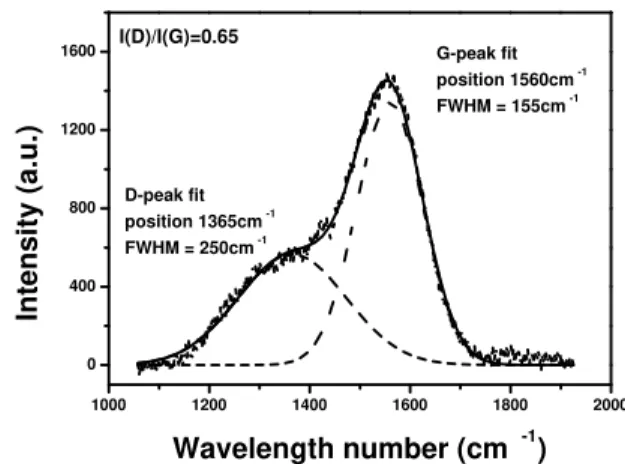
the [—CH2—]n. When the UHMWPE characteristics peaks are removed, a broad peak with two shoulders at approxi-mately 1360 cm−1 and 1560 cm−1can be observed in the
Raman spectrum as shown in Fig. 3. These two bands were fitted with two Gaussian functions and can be attributed to the D and G band of hydrogenated amorphous carbon [9]. Although, sp3
/sp2
ratios in the hydrogenated carbon films cannot be derived directly from the Raman spectra, some quantitative information can be extracted from the fitting as the position using full width at half maximum (FWHM) of the G and D peaks as well as the ratio of the D to G peak area - I (D)/I (G). The position of G and D lines, G peak’s FWHM and the peak integral intensity ratio I (D)/I (G) are somewhat correlated with the sp3
/sp2
bonding ratio [10].
1000 1200 1400 1600 1800 2000
0 400 800 1200
1600 I(D)/I(G)=0.65
D-peak fit position 1365cm-1 FWHM = 250cm-1
G-peak fit position 1560cm-1
FWHM = 155cm-1
Intensity (a.u.)
Wavelength number (cm -1)
Figure 3. Fitted Raman spectrum after removing the characteristic peaks of UHMWPE.
An important indication of the formation of diamond-like carbon (DLC) layer on the implanted polymer sur-face can be obtained from the Raman spectrum of implan-ted UHMWPE which exhibits characteristics typical for the DLC, including a disorder peak (D peak) at 1365 cm−1, and
a graphite-like peak (G peak) at 1560 cm−1 with a I (D)/I
(G) ratio of about 0.65.
3.2
Characterization by XPS
Currently, the analysis of the X-ray photoelectron spectra (XPS) of the C 1s core level peak has been successfully adopted to estimate the sp3
Gaussian and a Lorentzian) and by accounting the contri-bution of the background by the Shirley method. The first component is found at 284.4±0.1 eV (FWHM = 1.00±0.05 eV), and corresponds to sp2carbon atoms, while the second at 285.2±0.1 eV (FWHM = 1.10±0.05 eV) corresponds to sp3
carbon atoms. A third peak of much smaller intensity at 286.5 eV has also been added and is attributed to some C-O contamination formed at the surface of the samples. This contamination is due to air or residual gas exposure of the dangling bonds, which are formed by polymer chain dehy-drogenation [2]. The binding energy values found for the sp2
and sp3
components of the DLC C 1s spectra are con-sistent with the binding energies of 284.4 eV and 285.2 eV detected for C 1s peaks of graphite and diamond respecti-vely. The whole spectrum was deconvoluted into four dif-ferent contributions at 284.4 eV, 285.2 eV, 286.6 eV, and 288.3 eV. The nitrogen implantation causes an asymmetric broadening of C 1s XPS peak towards higher energies. At low nitrogen concentration these peaks could be respectively attributed to C-sp2
, C-sp3
, C-O and C=O or O-C-O chemi-cal bonding formed at the surface [12]. The oxygen present in the chemical structure of the treated polymer is probably due to the oxidation of the long-living radicals, phenomena that is widely reported in the literature. The fitting method for XPS data gives values for sp2
/sp3
ratios within hydro-genated carbon films, which are consistent with the results from other measurements [11,12]. In the sequence, the sp3
and sp2
carbon atom content was determined as the ratio of the corresponding peak area over the total C 1s peak area. Thus, the ratio of sp3
/sp2
hybridized C in the treated sam-ples was estimated to be about 60% indicating a formation of hard DLC layer.
292 290 288 286 284 282 280
5 10 15
C(1s) fitting curve
C=O C-O
C sp3
C sp2
Intensity (Counts x10
3 )
Binding energy (eV)
Figure 4. Deconvolution of the XPS C 1s peak of the PIII implan-ted polyethylene.
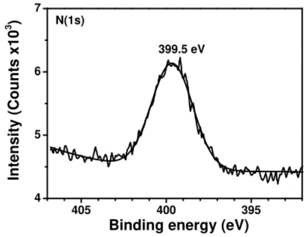
The XPS N1s peak for the nitrogen implanted UHMWPE is shown in Fig. 5. A N1s peak (FWHM = 2.9 eV) is found at 399.5 eV. Sjostrom et al. [13] have reported the calculations of two model systems in which an N atom is surrounded by sp2
hybridized carbon atoms or sp3
hybri-dized carbon atoms. The N1s binding energy for N- sp3
C
and N- sp2
C are 398.3 eV and 400.2 eV, respectively. It has also been reported that N1s peak position for nitrile (-C≡N) is at 399.4 eV [14]. Therefore, the peak at 399.5 eV in XPS spectrum of the PIII treated polyethylene may be the overlap of the two peaks (398.3 and 400.2 eV) or corresponds to ni-trile. In any way, the implanted nitrogen ions form chemical bonds with the polymer chains instead of forming precipi-tates by self-clustering (binding energy ∼402.0-403.0 eV) [14].
405 400 395
4 5 6 7
399.5 eV N(1s)
Intensity (Counts x10
3 )
Binding energy (eV)
Figure 5. N 1s peak of PIII implanted UHMWPE.
3.3
Characterization by Nanoindentation
te-chnique
Even with 4 g load the effect of the substrate bulk could not be avoided. So the conclusion is that lighter loads should be used until the limit where hardness measurement were independent of the substrate (type and roughness) and, in this way, uniquely attributed to DLC formed on the polymer surface. But we shall have in mind that there is a critical ba-lance between the load value and measurement error in such a way that smaller the load higher the measurement error.
Another point that needs to be mentioned is the neces-sity of performing multiple measurements for each depth. The measurement error inherent to nanoidentation techni-que is high and, in this way, statistical data treatment based on mean values is necessary for results with a good level of confidence.
0 500 1000 1500 2000 2500 3000 30
40 50 60 70 80 90
Hardness (MPa)
Displacement into surface (nm)
unimplanted - 4 g 6loads implanted 30´N - 4 g 6loads
Figure 6. Hardness of uninplanted and PIII implanted UHMWPE.
As illustrated in Fig. 6, we can see that PIII treatment has a pronounced hardening effect on UHMWPE. In fact the hardening level depends on the depth of the measurement and closer the surface we measured it more pronounced was the hardening effect. This result was already predictable be-cause improvement on polymer mechanical properties indu-ced by ion implantation is largely due to the formation of a three-dimensional covalent bonds network among the poly-mer chains. As the ions are implanted from the surface to the interior of the material, intensity of cross-linking bonds are expected to decrease in the same direction. This conclusion is supported by the literature [16].
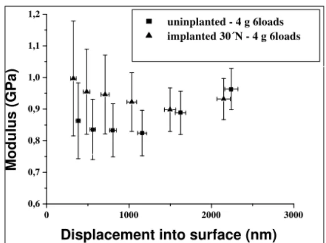
In this study, it was found that within depths of the order of 0.5 µm the hardness was improved by 50%. The hard-ness improvement is higher at distances closer to the surface but it was very difficult to measure it cause of the polymer characteristics already discussed. Therefore, significant sur-face modifications are confined to a very thin layer (<1µm) beneath the surface. Fig. 7 presents the enhanced elastic mo-dulus for modified UHMWPE, which also shows a tendency to get higher at the very surface of the sample.
0 1000 2000 3000
0,6 0,7 0,8 0,9 1,0 1,1 1,2
uninplanted - 4 g 6loads implanted 30´N - 4 g 6loads
Modulus (GPa)
Displacement into surface (nm)
Figure 7. Elastic modulus of uninplanted and PIII implanted UHMWPE.
4
Conclusions
Plasma immersion ion implantation has been demonstra-ted to be an effective treatment for surface modification of UHMWPE. The nitrogen ion bombardment has caused a significant decreasing of the hydrogen content in the poly-mer surface. That phenomenon represents, in fact, a ture modification of the polymer chemical chains. The struc-ture modification consists of bombardment of the polymer surface by nitrogen energetic ions, in such a way that the ions cause bond breakage or molecular chain scission by displacing atoms from polymer chains. The subsequent re-actions lead to free radical formation and new and stronger cross-linked bonds. So, new chemical species are created on polymer surface, which leads to better tribological proper-ties. The XPS results show that the initial surface layer has in fact been converted into hydrogenated amorphous carbon a new layer obtained on the polymer surface that is DLC.
Raman spectroscopy of treated samples has shown an enhanced luminescence background and a G and D bands centered at 1560 cm−1and 1365 cm−1, respectively.
XPS C 1s core level spectra of the modified layer were used for evaluation of the content of sp3
and sp2
carbon atoms at the polymer surface. The estimated ratio of sp3
/sp2
hybridized C in the treated samples strongly indicated the formation of DLC layer.
It has been proven that PIII can also significan-tly improve the surface hardness and elastic modulus of UHMWPE and one of the important conclusions of this work is that the improvement of the grounding and polishing processes permits easier evaluation of these mechanical pro-perties at the surface of the material.
an improved inertness. For UHMWPE prostheses applica-tion, the cross-linked bonds are usually obtained by gamma radiation sterilization process. But sterilization in air may be particularly harmful, because it may initiate a long-term oxidative process, which has a negative impact on the im-plant’s mechanical properties. Nitrogen PIII process eli-minates these disadvantages while keeping the benefits of cross-linked bonds.
Acknowledegments
One of the authors, A. R. Marcondes, wishes to thank Capes for his fellowship. FAPESP has also financially sup-ported this work. Another author, G. F. Gomes, gratefully acknowledges a post-doctoral fellowship from FAPESP.
References
[1] D. Lwise, D. J. Trantolo, D. E. Altobelli, M. J. Yaszemski, J. D. Gresses, and E. R. Schwarts, Encyclopedic Handbook of Biomaterials and Bioengineering A,2, 1759 (1995). [2] J. S. Chen, S. P. Lau, Z. Sun, B. K. Tay, G. Q. Yu, F. Y. Zhu,
D. Z. Zhu, and H. J. Xu, Surf. Coat. Techol.138, 33 (2001). [3] W. Shi, X. Y. Li, and H. Dong, Wear, 250, 544 (2001). [4] D. Ikeda, M. Ogawa, Y. Hara, Y. Nishimura, O. Odusanya, K.
Azuma, S. Matsuda, M. Yatsuzuka, and A. Murakami, Surf. Coat. Technol.156, 301 (2002).
[5] M. Konuma,Film Deposition by Plasma Techniques, Sprin-ger, Berlin, p. 171 (1992).
[6] M. Ueda, L. A. Berni, J. O. Rossi, J. J. Barroso, A. F. Beloto, and E. Abramof, Surf. Coat. Technol.136, 28 (2001). [7] A. Valenza , A. M. Visco , L. Torrisi, and N. Campo, Polymer,
45, 1707 (2004).
[8] D. Lin-Vien, N. B. Colthup, W. G. Fateley, and J. G. Gras-selli,Infrared and Raman Characteristic Frequencies of Or-ganic Molecules, Academic Press, Inc (1991).
[9] J. Y. Chen, L. P. Wang, K. Y. Fu, N. Huang, Y. Leng, Y. X. Leng, P. Yang, J. Wang, G. Wan, H. Sun, X. Tian, and P. K. Chu, Surf. Coat. Technol.156, 289 (2002).
[10] J. Robertson, Mat. Sci. Eng. Reports37, 129 (2002). [11] P. Merel, M. Tabbal, M. Chaker, S. Moisa, and J. Margot,
Appl. Surf. Sci.136, 105 (1998).
[12] J. Filik, P. W. May, S. R. J. Pearce, R. K. Wild, and K. R. Hallam, Diamond Rel. Mat.12, 974 (2003).
[13] H. Sjostrom, S. Stafstrom, M. Boman, and J. E. Sundgen, Phys. Rev. Lett.75, 1331 (1995).
[14] A. Toth, T. Bell, I. Bertoti, M. Mohai, and B. Zelei, Nucl. Instr. and Meth. B148, 1131 (1995).
[15] H. C. Ong, R. P. H. Chang, N. Baker, and W. C. Oliver. Surf. Coat. Technol.89, 38 (1997).