Abstract
The dynamic behavior of variable stiffness composite laminated (VSCL) plate with curvilinear fiber orientation subjected to in-plane end-loads is investigated. A variable stiffness design can increase the laminated composite structural performance and also provides flexibility for trading-offs between various structural prop-erties. In each ply of the VSCL plate, the fiber-orientation angle assumed to be changed linearly with respect to horizontal geometry coordinate. The spline finite strip method based on both classical as well as higher order shear deformation plate theories is formulated to explain the structural behavior. The panel is assumed containing internal square delamination regions with friction and contact conditions at delaminated interfaces are not considered. In order to demonstrate the capabilities of the developed method in predicting the structural dynamic behavior, some representing results are obtained and compared with those available in the literature. The effects of change in curvilinear fiber orientation angles on the struc-tural stability is studied. The obtained results show very good conformity in comparison with those exists in the available litera-ture.
Keywords
stability, variable stiffness, curvilinear fiber composite, finite strip method, delamination.
Stability Analysis of Variable Stiffness Composite Laminated
Plates with Delamination Using Spline-FSM
1 INTRODUCTION
Aeronautical, space and marine structures are among disciplines where the least structural weight besides providing high available strength must be achieved. Thus, thin-walled structures will usually come to play. Every structural component especially those thinner in thickness under in-plane har-monically varying excitation added to a constant mean load, meets situations where the instability conditions may appear. The amplitude of the dynamic instability load may even be lower than the
Jamshid Fazilati a
a Assistant professor, Aerospace Research
Institute, Tehran, P.O.box: 14665-834, Iran, [email protected]
http://dx.doi.org/10.1590/1679-78253562
value corresponding to static bifurcation point. These excitation conditions are prevalent in case of mechanical structures as well as fluid-structural interactions.
The traditional composite designs consider the composite lamina properties to be constant throughout the entire ply by the usage of straight and uniformly spaced fibers. This type of con-struction provides constant unchanged stiffness throughout the whole lamina. A ply with variable mechanical properties could be achieved by changing the fiber orientation angle with respect to the locality. With the automated fiber placement technology, it is possible to fabricate composite plies with variable fiber orientations within their geometrical domain. As a result of changed fiber orien-tation, the ply achieves variable directional stiffness through the geometry and may be called as a variable stiffness composite laminate (VSCL). On the other hand, a widespread defect of composite laminated structures is the debonding of layers called delamination. Delamination occurrence causes total strength reduction of the structure and activates low energy local instability and failure modes. So it is of high importance to calculate the stiffness reduction of a delaminated structure. Therefore, it is essential to study the various effects of loading and delamination on the dynamic characteristics and response of layered plates under static and periodic in-plane loads.
investigated the parametric instability problem of flat and curved shell panels with and without internal cutout and longitudinal stiffeners under uniform in-plane loadings.
In this paper the static as well as dynamic stability behavior of moderately thick laminated flat panels containing delamination subjected to inplane loadings has been investigated. The laminate assumed to be variable stiffness due to curvilinear fiber placement that changes linear in the panel longitudinal direction. The in-plane loading is assumed to change harmonically with time. A B-spline version of FSM has been developed. The formulations are based on both the classical thin plate theory and the Reddy type higher order shear deformation theory in order to include the transverse shear stresses effect in case of moderately thick structures. The governing equations are derived using full energy concepts on the basis of the principle of virtual work. The dynamic behav-ior including natural frequencies as well as instability load-frequency margins are extracted utilizing the Bolotin’s first order approximation followed by an eigenvalue analysis. Some representative problems are numerically studied and compared to those in the literature wherever available. To the best of the author’s knowledge, this is the first application of B-spline FSM to the problem. Moreo-ver, many studies have been devoted to the curvilinear fiber VSCL panels, while there are few pub-lished works on the parametric instability of curvilinear fiber variable stiffness composite laminated panels with delamination.
2 FORMULATION
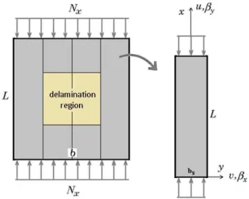
The assumed model includes a flat square laminated panel with a squared through-the-width or embedded delamination zone. The panel laminates are made from curvilinear (linearly changed) fiber orientations. The geometry is divided to a number of longitudinally adjacent finite strips. Fig-ure 1 shows a sample numerical mesh of a geometry of width b, length L and total thickness t. The geometry is made from number of strip elements of length L and width bs. A typical embedded sin-gle delamination zone is also indicated in the figure. A uniform loading as prestress is assumed on finite strips. The loading is consisted from a non-changing (static) component and a harmonically changing (dynamic) component which are indicated using S and D superscripts, respectively. The loading as a function of the static buckling load could be expressed as,
S D
x cr cr
N =a N +a N coswt (1)
With w, aS and aD as the excitation frequency, static part coefficient and dynamic part
coeffi-cient, respectively.
The assumed model displacement field based on Reddy-type third order shear deformations in thickness direction (zero shear at top and bottom surfaces), may be expressed as,
2 2
0
0 * 3
0
0 * 3
* 4 0
0 3
* 4 0
3 . / ( , , ; ) . . / ( , , ; ) . , / ( , , ; ) / xz x x x yz y y y
x t x
y t y
C dw dx
u x y z t u z C z
C dw dy
v x y z t v z C z
dw dx
w x y z t w
dw dy
g b
b b g b
b b b b
b b
ìï =
-ï
ì ï
ï = + + ï
ï ï = +
ï ï
ïï = - - ï
í í é ù
ï ï = - ê + ú
ï ï ë û
ï = ï
ï ï é ù
ïî ïï = êë - úû
ïî
Figure 1: Typical delaminated plate finite strip mesh, finite strip geometry and loading.
Where u v w, , are the displacement components of any arbitrary point, u v w0, ,0 0are the corre-sponding displacement components at the strip mid-surface, and b bx, y are the rotations around y and x axis, respectively. The pointer C is set to 1 and may be set to 0 in case of classical plate theo-ry assumptions.
The mid.-surface displacement field is approximated as multiplication of longitudinal-directional approximation functions. In longitudinal direction of a finite strip, the summation of a series of B3-splines are employed while in the strip width, inplane linear Lagrange functions in conjunction with out of plane third order Hermitian ones are chosen (Fazilati and Ovesy, 2013). Any type of bounda-ry constraints (free, hinged, clamped) may be implemented according to the approximation dis-placement functions chosen.
The linear strains for flat geometry are calculated through,
, , , , , , , , .( ) .( ) x x y y
xy y x
yz z y
xz z x
u v
u v
C v w
C u w
e e g g g ìï = ïï ïï =
ïïï = +
íï
ïï = +
ïï
ï = +
ïïî
(3)
where ‘,’ defines a differentiation operator. Substituting the displacement functions (equation 2) into the strain equations (equation 3) leads to the strain field as:
(0) (1) 2 (2) 3 (3)
(0) (1) 2 (2) 3 (3)
(0) (1) 2 (2) 3 (3)
(0) (1) 2 (2) 3 (3)
(0) (1) 2 (2) 3 (3)
. . .
. . .
. . .
. . .
. . .
x x x x x
y y y y y
xy xy xy xy xy
yz yz yz yz yz
xz xz xz xz xz
z z z
z z z
z z z
z z z
z z z
e e e e e
e e e e e
g g g g g
g g g g g
g g g g g
ìï = + + +
ïï
ïï = + + +
íï
ïï = + + +
ïïî
ì = + + +
í
= + + +
ïïï ïïïî
where the strain coefficients are defined as:
(
)
(
)
(
)
(
)
(
)
(
)
(
)
(
)
(
)
(
)
(0) (0) (0) 0 0 0 0
, , , , (0) (0) 0 0
, ,
(1) (1) (1)
, , , , (2
(2) (2) (2)
(3) (3) (3) * * * *
, , , ,
, , , , +
, . - , +
, , , - ,
-,
, , 0, 0, 0
, , . , - ,
-x y xy x y y x
yz xz y y x x
x y xy x x y y x y y x
yz x y xy
x y xy x x y y x y y x
u v u v
C w w
C
e e g
g g b b
e e g b b b b
g e e g
e e g b b b b
ìï = ïï = ïï = ïï íï = ïï ïï = ïïî
(
)
(
)
(
) (
)
( )
) (2) * *
(1) (1) (3) (3)
, . -3 , 3
, , 0, 0
xz y x
yz xz yz xz
C
g b b
g g g g
ìïï
ïïï =
íï
ïï = =
ïïî
(5)
Solution of the instability problems is sought through the principle of virtual work. The total energy of a strip is defined as summation of kinetic (T), pre-stress (Ug) and elastic strain (Ue) ener-gy components:
e g
U U T
P = - - (6)
Where the energy terms could be defined as,
(
)
(
)
(
)
2
2 2 2 2 2
2
2
2 2 2 2 2
, , , , ,
2
(0) (1) (2) (3) (0) (1) (2) (3) 1
2
12
12
. .
t o o o
x y
o o o
t
g x x x x x x y x
T T
e
t
T u v w dxdy
t
U N u v w C dx dy
U N M O P Q RT U dx dy
r
b b
b b
e e e e g g g g
æ ö÷
ç ÷
ç + + + ÷
ç ÷÷
çè ø
æ é ù ö÷
ç ê ú ÷
ç + + + + ÷
ç ê ú ÷÷
çè êë úûø
æ ö÷
ç + ÷
ç ÷ çè ø
òò
òò
òò
= + = = (7)With denoting of the material mass density as ߩ, differentiation with respect to time as a upper dot and a matrix transpose operator as superscript T. The force resultants (N,ܯ,O,P,Q,R,T,U) can be related to the strain terms via the curvilinear fiber laminated material equivalent stiffness matri-ces. i.e.: (0) (1) (2) (3) { } { } [ ] [ ] [ ] [ ] { } { } [ ] [ ] [ ] [ ] { } { } , { } [ ] [ ] [ ] [ ] { } { } { } [ ] [ ] [ ] [ ] { } { }
N A B D E Q
M B D E F R
O D E F I T
P E F I H U
e e e e ì ü ï ï
ì ü é ù ì ü
ï ï ï ï ï ï
ï ï ê ú ï ï ï ï
ï ï ê ú ï ï ï ï
ï ï ï ï ï
ï ï ï ï ï
ï ï= ê ú ï ï ï
í ý ê ú í ý í ý
ï ï ê ú ï ï ï
ï ï ï ï ï
ï ï ê ú ï ï ï
ï ï ï ï ï
ï ï ê ú ï ï ï
ï ï ï
î þ ë û ïïî ïïþ î
(0) (1) (2) (3) [ ] [ ] [ ] [ ] { } [ ] [ ] [ ] [ ] { } [ ] [ ] [ ] [ ] { } [ ] [ ] [ ] [ ] { }
S S S S
S S S S
S S S S
S S S S
A B D E
B D E F
D E F I
E F I H
g g g g
é ù ìïï üïï
ê ú ï ï
ê ú ï ï
ï ï ï
ï ê ú ï ï
ï= ê ú íï ïý
ï ê ú ï ï
ï ê ú ï ï
ï ï ï
ï ê ú ï ï
ï ï ï
ïþ êë ú ïû îï ïïþ
(8)
Substituting the strain and force resultant equations in energy integrals (equation 7), minimiz-ing the energy equilibrium equation 6, factorizminimiz-ing with respect to the degrees of freedom vectors, and some further handlings including assembling the strip equations and implementing of necessary boundary conditions, a Mathieu-type differential governing equation is obtained as,
( S cos D) 0
g g
Where M, K, KgS and KgD are the global structural matrices corresponding respectively to mass, elastic strain, static stress and dynamic initial stress energies. d is the global vector of uncon-strained degrees of freedom. By implementing the Bolotin’s first order approximation corresponding to the period twice the loading period, which is more critical (Bolotin, 1964), the time varying vec-tor,d, is approximated as:
(
1)
(
1)
2 2
sin cos
A t B t
d = w + w (10)
A and B are time-independent coefficient vectors called degrees of freedom vectors. Substitution of equation 10 into equation 9, factorization of harmonic terms and setting their coefficients to zero leads to a set of homogenous equations. For a non-trivial solution of unknown vectors A and B, the determinants of the coefficient matrices should be set to zero. The governing equations are reduced to two subsequent eigenvalue problems as,
1
2 2
1 2
0 1 0
0 0
4 0
S S D D
g g
S S D D
g g
K a K a K M
M
K a K a K w
æ - + ö÷ æ ö
ç ÷ ç ÷
ç ÷- ç ÷÷=
ç ÷ ç ÷
ç - - ÷ ç ÷
ç è ø
è ø (11)
The equations corresponding to vectors A and B are not coupled and can be solved separately which reveals the two boundaries of the instability region for the structure in terms of loading pa-rameter sets of ( ,a aS D, )w .
2.1 Curvilinear Fiber Simulation Considerations
Using machine fiber placement technologies, it is possible to change the fiber orientation through the geometry. The resulting production is called as a curvilinear fiber placement. In this research it is assumed that the fiber angle changes linearly just in the longitudinal direction of the geometry. As a result, the lamination layup in the panel width is constant while changing in the longitudinal direction. The changing fiber angle is denoted by a two-angle set <T0,T1> where the former one and the latter are the fiber angle at the plate middle section and plate longitudinal ends, respective-ly. In other words, the fiber angle in a single ply is symmetric with respect to the plate middle sec-tion. So, the fiber angle at every arbitrary point in the geometry is given by the following equation,
0 1 0
| / 2 |
( , ) ( )
/ 2
x L
x y T T T
L
q = + - - (12)
Figure 2: Curvilinear variable fiber orientation in a single lamina.
2.2 Delamination Modeling Technique
In the delamination region, the plate is actually a set of two thinner plates. To bring a single delam-ination effects into consideration, the main idea is to use double strips in the thickness direction. This means that the whole plate is composed of two similar layers of strip meshes with special lay-ups. Inside the delamination zone, the two layers are independent and has no connections (note that the probable contact between two adjacent layers is ignored at present.). Out of delamination zone, all of degrees of freedom of the two layer must rigidly linked to each other via knots’ merging pro-cess. The corresponding strips in upper and lower layers have the same geometrical and numerical characteristics. According to Figure 3, the strip knots of the same planar positions are merged to-gether in all the perfect panel areas and also in the delamination zone edges. It is important to have knots on the edges of the delamination region. This approach could also be generalized for the case geometry with N delamination in thickness direction (N+1 layers is needed to be defined). Every strip layer has the same geometry properties but are different in bending stiffness. To fulfill the true bending properties of every layer in a strip with respect to the plate mid.-surface, every layer lay-up is considered similar to the whole plate layup with the redundant layers’ material changed to a null stiff-less and weight-less one. (see Figure 3) These considerations provide the physical conditions at the edges of the delamination zone.
3 RESULTS AND DISCUSSION
The first two natural frequencies and fundamental buckling strength of a laminated composite rec-tangular plate are investigated. The lamina material properties and the model geometry are charac-terized as,
1 1 2 12
3 12 2
134.4 , / 13, 0.25 0.127 , / 10, / 125 ,
/ 0;0.2;0.4;0.6 / 0.5, 1480 /
E GPa E E L m L b L t
d L
G E kg m
n r
ì = = = ì
ï ï = = =
ï ï
í í
ï = = ï =
ï ïî
î (13)
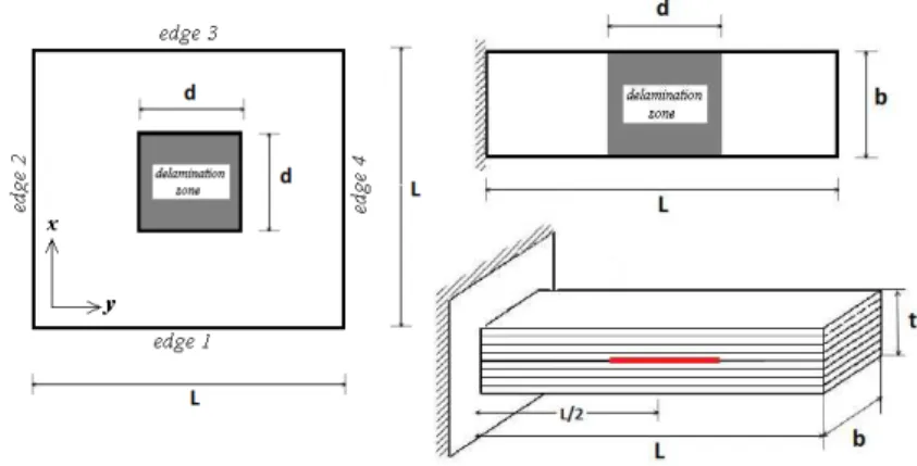
The laminate has 8 layers with fixed orientation lay-up [0/90/0/90]s. A central through-the-width delamination in the mid layer is considered as shown in Figure 4. Table 1 shows the results for the first two natural frequencies as well as fundamental critical buckling load. The results from higher order deformation theory, layerwise theory and experimental tests are also provided from the literature. A good agreement could be seen between the present FSM calculations and the reference ones.
Figure 4: The geometry and delamination position of the cantilever plate (left) and square plate (right).
d/L 0.0 0.2 0.4 0.6
Exp. (Shen, 1992) w1 (Hz) 79.83 78.17 75.38 66.96
HST (Radu, 2002) w1 (Hz) 82.12 81.19 76.48 67.26
w2 (Hz) 513.3 509.24 469.02 369.08
Pcr (N) 16.363 16.08 15.054 12.712
FSDT-LWT (Ovesy, 2014) w1 (Hz) 82.03 80.75 75.98 66.83
w2 (Hz) 506.55 508.37 465.37 365.81
Pcr (N) 16.208 15.933 15.084 12.961
CLT FSM (present) w1 (Hz) 82.16 81.23 75.49 65.65
w2 (Hz) 514.87 513.34 459.36 388.21
Pcr (N) 16.34 16.18 14.88 12.30
HST FSM (present) w1 (Hz) 82.10 81.15 75.34 65.50
w2 (Hz) 512.59 511.06 453.82 384.70
Pcr (N) 16.33 16.16 14.85 12.26
The first eight natural frequencies of three-layer square VSCL plates of diverse thickness, for simply-supported and clamped boundary conditions are extracted and presented in comparison to higher order FEM results of Akhavan and Ribeiro (2011) in Table 2-5. The model consists of a square plate of unit edge lengths with two length to thickness ratio (L/t) of 100 and 10. Three dif-ferent ply fiber orientation angle layups are considered including [<0,45>/<-45,-60>/<0,45>], [<30,0>/<45,90>/<30,0>], [<90,45>/<60,30>/<90,45>]. The material properties of the plies are given as,
1 1 2 12
3 12 2
173 , / 24.028, 0.29 / 0.52, 1540 /
E GPa E E
G E kg m
n r
ì = = =
ïï
íï = =
ïî (14)
The results show the very good consistency of the FSM higher order as well as classical formu-lations.
[<0,45>/<-45,-60>/<0,45>] [<30,0>/<45,90>/<30,0>] [<90,45>/<60,30>/<90,45>] HST FEM CLT-FSM HST-FSM HST
FEM CLT-FSM
HST-FSM HST FEM CLT-FSM HST-FSM Akhavan
(2011) present present
Akhavan
(2011) present present
Akhavan
(2011) present present
1 358.488 357.223 358.948 308.799 309.963 309.513 329.688 327.809 330.602
2 589.90 589.854 591.870 503.799 505.921 506.397 539.407 536.031 539.927
3 960.361 964.726 967.324 845.509 849.859 853.589 886.392 886.284 886.995
4 1075.21 1081.566 1076.831 1131.31 1142.172 1133.931 1091.20 1093.037 1093.440
5 1327.88 1331.970 1329.703 1279.85 1286.756 1293.531 1279.90 1273.095 1280.431
6 1474.67 1475.865 1484.581 1307.40 1319.000 1311.984 1401.87 1402.226 1400.969
7 1726.71 1733.524 1730.946 1701.66 1712.942 1716.874 1755.53 1686.402 1702.978
8 2137.13 2099.267 2114.419 1758.95 1762.449 1775.964 1809.82 1800.674 1806.170
Table 2: Linear natural frequencies (Hz) for simply supported thin square three-ply VSCL(L/t=100).
[<0,45>/<-45,-60>/<0,45>] [<30,0>/<45,90>/<30,0>] [<90,45>/<60,30>/<90,45>]
HST FEM
CLT-FSM
HST-FSM HST FEM
CLT-FSM
HST-FSM HST FEM
CLT-FSM
HST-FSM Akhavan
(2011) present present
Akhavan
(2011) present present
Akhavan
(2011) present present
1 579.398 585.860 581.796 667.177 674.701 669.276 710.771 719.218 714.221
2 821.532 830.278 828.713 862.919 872.278 870.286 912.183 922.956 917.268
3 1225.79 1238.937 1245.285 1234.64 1248.612 1256.165 1335.49 1351.924 1347.236
4 1493.76 1526.021 1500.899 1701.04 1730.614 1721.424 1689.69 1723.643 1710.075
5 1726.96 1766.256 1741.505 1775.56 1809.472 1803.511 1836.71 1878.085 1860.086
6 1775.16 1797.064 1817.967 1902.48 1944.446 1915.429 1987.55 2021.619 2010.531
7 2135.76 2182.707 2166.721 2269.83 2316.398 2306.725 2278.23 2298.254 2301.067
8 2443.53 2479.814 2519.071 2310.69 2346.615 2373.940 2466.75 2515.019 2518.218
[<0,45>/<-45,-60>/<0,45>] [<30,0>/<45,90>/<30,0>] [<90,45>/<60,30>/<90,45>]
HST FEM HST-FSM HST FEM HST-FSM HST FEM HST-FSM
Akhavan
(2011) present
Akhavan
(2011) present Akhavan (2011) present
1 2934.69 2928.605 2620.4 2624.798 2746.66 2739.410
2 4688.30 4693.783 4225.74 4242.711 4402.32 4393.163
3 7000.96 7009.894 6704.11 6749.203 6915.87 6928.962
4 7324.22 7366.613 7121.26 7136.770 7058.72 7066.031
5 8471.78 8486.471 8383.48 8419.139 8254.38 8247.497
6 10448.8 10525.667 9317.14 9394.306 9626.07 9648.588
7 10907.0 10984.944 11079.5 11181.187 11158.9 11067.479
8 11653.3 11657.977 11762.0 11793.071 11486.5 11503.689
Table 4: Linear natural frequencies (Hz) for simply supported square three-ply VSCL(L/t=10).
[<0,45>/<-45,-60>/<0,45>] [<30,0>/<45,90>/<30,0>] [<90,45>/<60,30>/<90,45>]
HST FEM HST-FSM HST FEM HST-FSM HST FEM HST-FSM
Akhavan
(2011) present
Akhavan
(2011) present
Akhavan
(2011) present
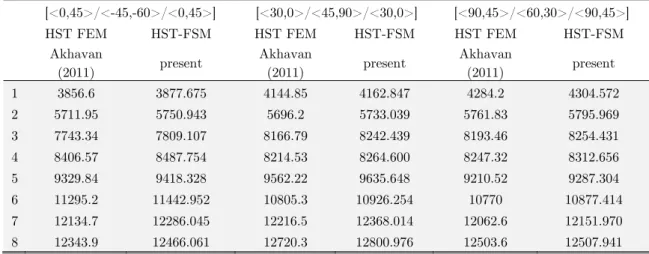
1 3856.6 3877.675 4144.85 4162.847 4284.2 4304.572
2 5711.95 5750.943 5696.2 5733.039 5761.83 5795.969
3 7743.34 7809.107 8166.79 8242.439 8193.46 8254.431
4 8406.57 8487.754 8214.53 8264.600 8247.32 8312.656
5 9329.84 9418.328 9562.22 9635.648 9210.52 9287.304
6 11295.2 11442.952 10805.3 10926.254 10770 10877.414
7 12134.7 12286.045 12216.5 12368.014 12062.6 12151.970
8 12343.9 12466.061 12720.3 12800.976 12503.6 12507.941
Table 5: Linear natural frequencies (Hz) for fully clamped square three-ply VSCL (L/t=10).
CCCC CSCS CCCF CFCF SSSS SSSF SFSF
d/L=0.0 1 1.9463 1.7064 1.3644 1.2983 1.2720 0.6959 0.6825
2 2.0423 1.9769 1.6145 1.3896 1.7145 1.0952 0.6996
3 2.4249 2.3750 2.1001 1.6630 2.0856 1.5908 1.0362
4 2.5558 2.5320 2.3005 1.7564 2.3261 1.9166 1.4392
d/L=0.2 1 1.9438 1.7050 1.3636 1.2981 1.2717 0.6959 0.6825
2 1.9739 1.9206 1.6045 1.3875 1.6749 1.0940 0.6996
3 2.3901 2.3554 2.0520 1.6629 2.0833 1.5739 1.0361
4 2.4182 2.3692 2.2494 1.7308 2.2434 1.9101 1.4360
d/L=0.4 1 0.9137 0.9126 0.9122 0.9104 0.9067 0.6904 0.6716
2 0.9272 0.9271 0.9271 0.9270 0.9255 0.9017 0.6971
3 1.0062 1.0061 1.0060 1.0058 1.0059 0.9251 0.9019
4 1.0963 1.0914 1.0884 1.0787 1.0546 1.0054 0.9250
d/L=0.6 1 0.5520 0.5500 0.5500 0.5478 0.5377 0.5284 0.5177
2 0.6657 0.6654 0.6651 0.6644 0.6426 0.6334 0.6227
3 0.7306 0.7303 0.7301 0.7296 0.7278 0.6908 0.6739
4 0.7391 0.7388 0.7387 0.7383 0.7384 0.7304 0.7008
Table 6: Buckling of square three-ply VSCL plate with central embedded delamination (GPa).
CCCC CSCS CCCF CFCF SSSS SSSF SFSF
d/L=0.0 1 3893.0 3608.0 3223.9 3124.5 2936.8 2242.1 2145.6
2 5807.4 5044.1 4188.5 3378.1 4716.2 3256.6 2389.8
3 7842.3 7625.2 6158.2 4489.2 7012.6 5189.6 3629.2
4 8628.3 7692.0 7162.4 6454.2 7439.3 6361.1 5540.4
d/L=0.2 1 3892.9 3608.0 3223.1 3124.5 2936.8 2241.8 2145.6
2 5767.8 5016.4 4187.6 3376.0 4690.9 3256.0 2388.9
3 7656.9 7534.5 6106.0 4489.1 6850.9 5152.6 3629.1
4 8626.9 7624.1 7129.4 6377.1 7438.4 6339.7 5483.4
d/L=0.4 1 3822.3 3555.2 3197.1 3101.5 2894.7 2227.0 2130.0
2 5469.7 4793.3 4117.2 3350.5 4475.6 3215.1 2379.1
3 6763.9 6693.4 5711.7 4417.0 5884.2 4812.7 3584.9
4 7151.4 6773.3 6682.2 5844.1 6684.5 5885.0 4971.5
d/L=0.6 1 3338.7 3190.6 3004.0 2906.4 2685.8 2159.4 2063.1
2 4279.3 4151.2 3624.5 3222.6 3968.1 2996.8 2329.8
3 4680.5 4275.9 4348.9 3778.7 4109.4 4052.8 3299.5
4 5831.8 5545.8 4893.2 4563.3 4874.9 4239.9 4157.6
Table 7: Natural frequencies of square three-ply VSCL plate with central embedded delamination (Hz).
Figure 6 depicts the fundamental free vibration mode shape in different boundary condition sets for the case of three-ply VSCL plate with central 36% delamination area.
Figure 5: Change in static and dynamic instabilities due to delamination area growth for different constraints.
VSCL square plate CCCC CSCS CCCF
CFCF SSSS SSSF SFSF
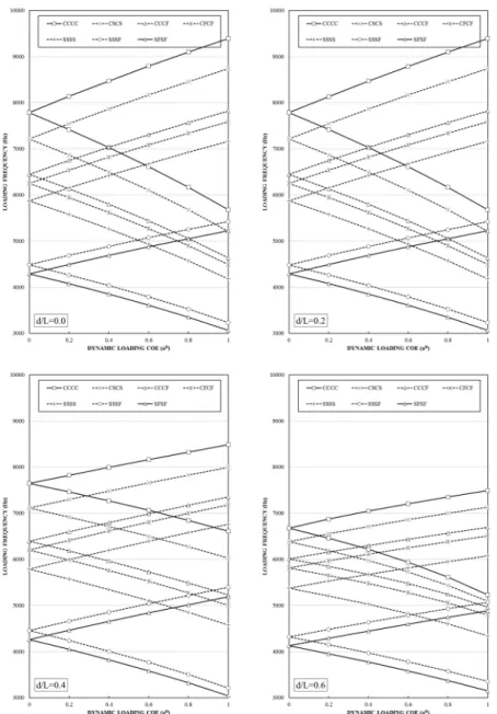
Figure 7 depicts the change in dynamic instability regions map of the perfect and delaminated VSCL panel with respect to different loading amplitude and frequencies. A pure longitudinal har-monic loading (aS=0.0) is assumed. The results show that the burst of delamination shifts the base instability frequencies (aD=0.0) toward slightly more critical lower ones while shrinks the instability region. A 4% delamination shows very ignorable results while higher delaminations make more sig-nificant changes.
Clamped VSCL plate containing a central 36% delamination region is considered with the refer-ence lay-up [<0,0>//<90,90>/<0,0>]. The central fiber angles in all layers (T0) is changed and the instability regions under inplane longitudinal uniform loading is extracted. Figure 8 depicts the instability region limits of various lay-ups. A pure dynamic loading is assumed. The results show that with change in central lay-up, the instability frequencies shift initially to the higher ones and then to the lower ones. A lay-up with fiber angles of [<15,0>//<-75,90>/<15,0>] benefits with higher instability frequencies that may interpreted to higher stable lay-up of the panel. It is also shown that in case of unchanged central fiber angles, the lay-up [<0,15>//<90,-75>/<0,15>] pre-sented higher instability frequencies. The study demonstrates a slightly higher effect of changing the central fiber angle in comparison with change in end fiber angles.
Figure 8: Dynamic instability region for clamped delaminated VSCL plate with different central fiber angles (d/L=0.6).
Figure 9: Dynamic instability region for clamped delaminated VSCL plate with changing static preload coefficient (d/L=0,0.6).
4 CONCLUSIONS
The static as well as dynamic stability behavior of moderately thick variable stiffness composite laminated (VSCL) plates containing inter-ply square delamination region is investigated by using of a higher order B-spline finite strip formulation. A harmonically time-varying in-plane longitudinal loading is assumed. The friction and contact effects at delaminated interfaces are neglected. The governing equations are derived using full energy concepts on the basis of the principle of virtual work. The dynamic parametric instability load-frequency margins are extracted utilizing the Bo-lotin’s first order approximation followed by an eigenvalue analysis. Comparisons imply that the spline formulation is a reliable tool in calculation of delamination effects as well as variable stiffness laminated plates stability problems. To the best of the author’s knowledge, this is the first applica-tion of B-spline FSM to the problem. Some representative results with change in lay-up, boundary conditions and delamination size are provided. The results show that the growth of the delamina-tion region made more significant destabilizing effects for the most constrained cases. It is also shown that proper fiber angle design may lead to minimize the delamination effects on the stability of the plate. The instability of the panel shifts to occur at lower loading frequencies as a delamina-tion growing but the severity of changes depends on the type of out-of-plane boundary condidelamina-tions.
References
Akhavan H, Ribeiro P (2011). Natural modes of vibration of variable stiffness composite laminates with curvilinear fibers. Composite Structures 93(11): 3040–3047.
Bolotin, V. V. (1964). The dynamic stability of elastic systems, Moscow: GITTL 1956. English translation. San Francisco: Holden-Day.
Fazilati, J., Ovesy, H.R. (2013). parametric instability of laminated longitudinally stiffened curved panels with cut-out using higher order FSM. Composite Structures 95:691–696.
Gurdal Z., Olmedo R. (1993). In-plane response of laminates with spatially varying fiber orientations-variable stiff-ness concept. AIAA Journal 31:751–758.
Hu, N., Fukunaga, H., Kameyama, M., Aramaki, K., Chang, F.K. (2002). Vibration analysis of delaminated compo-site beams and plates using a higher-order finite element. International Journal of Mechanical Sciences 44:1479–1503. Hyer M, Lee H. (1991). The use of curvilinear fiber format to improve buckling resistance of composite plates with central circular holes. Composite Structures 18:239–261.
Mohanty, J., Sahu, S.K., Parhi, P.K. (2015). Parametric instability of delaminated composite plates subjected to periodic in-plane loading. Journal of Vibration and Control 21 (3):419-434.
Ovesy, H.R., Fazilati, J. (2012). Buckling and free vibration finite strip analysis of composite plates with cutout based on two different modeling approaches. Composite Structures 94(3):1250–1258.
Ovesy, H.R., Fazilati, J. (2012). Parametric instability analysis of moderately thick FGM cylindrical panels using FSM. Computers and Structures 108–109:135–143.
Ovesy, H.R., Fazilati, J., Mahmoudabadi, M.R. (2014). Finite strip buckling and free vibration analysis of laminated composite plates containing delamination using a first order layerwise theory. in B.H.V. Topping, P. Iványi, (Edi-tors), "Proceedings of the Twelfth International Conference on Computational Structures Technology", Civil-Comp Press, Stirlingshire, UK, Paper 24. doi:10.4203/ccp.106.24
Parhi, P.K. Bhattacharyya, S.K., Sinha, P.K. (2001). Hygrothermal effects on the dynamic behavior of multiple delaminated composite plates and shells. J Sound Vibration 248(2):195-214
Radu, A.G., Chattopadhyay, A. (2002). Dynamic stability analysis of composite plates including delaminations using a higher order theory and transformation matrix approach. International Journal of Solids and Structures 39:1949– 1965.
Shen, M.-H. H., Grady, J. E. (1992). Free Vibrations of Delaminated Beams, AIAA Journal 30(5):1361-1370.
Tornabene F., Fantuzzi N., Bacciocchi M., Viola E. (2015). Higher-order theories for the free vibrations of doubly curved laminated panels with curvilinear reinforcing fibers by means of a local version of the GDQ method. Compo-sites Part B 81:196–230.