“© © 2010 IEEE. Personal use of this material is permitted. Permission from IEEE must be obtained for all other uses, in any current or future media, including reprinting/republishing this material for advertising or promotional purposes, creating new collective works, for resale or redistribution to servers or lists, or reuse of any copyrighted component of this work in other works.”
The definitive version of this article is available at
http://ieeexplore.ieee.org
Published as: Fernandes, C.A.; Lima, E.B.; Costa, J.R., "Broadband Integrated Lens for Illuminating Reflector Antenna With Constant Aperture Efficiency," Antennas and Propagation, IEEE Transactions on , vol.58, no.12, pp.3805,3813, Dec. 2010 doi:
IEEE Proof
Web Version
Broadband Integrated Lens for Illuminating Reflector
Antenna With Constant Aperture Efficiency
Carlos A. Fernandes, Senior Member, IEEE, Eduardo B. Lima, and Jorge R. Costa, Senior Member, IEEE
Abstract—A new integrated shaped lens antenna configuration is
described with frequency stable radiation pattern and phase center position across a broad 1:3 frequency band, which can be used for focal plane reflector feeding in quasi-optical radio telescope systems. The lens is compatible with the integration of ultrawide-band uniplanar printed feeds at its base and equally broadultrawide-band mixing devices, like the Hot Electron Bolometer (HEB), although these are not used in the present work. Measurements on a scaled mm-wave lab prototype have confirmed stable performance versus frequency, with only 1 dB directivity variation, and better than 94% Gaussicity, thanks to the possibility to impose a predefined output radiation pattern template. Simulations were performed to test the illumination of an off-set parabolic reflector by the lens radiation pattern, which confirmed reasonably constant aperture efficiency in the order of 78% across the 100% bandwidth.
Index Terms—Broadband stable radiation pattern, broadband
stable phase center position, integrated lens antennas, millimeter-and submillimeter wave antennas, reflector feed.
I. INTRODUCTION
S
UBMILLIMETER wave radio telescopes can collect radi-ation from some of the coldest and most distant objects in the Universe. To circumvent the atmospheric attenuation, these telescopes are either mounted at high altitude stations like the Atacama Large Millimeter/submillimeter Array (ALMA) [1] or at space vehicles like the Herschel Space Observatory [2]. In Herschel and in many submillimeter wave radio telescopes, bolometers are used as detectors [3] and can operate from microwave up to ultraviolet [4]. The Hot Electron Bolometer (HEB) can even be used for coherent receivers [5] and when integrated with broadband antennas (like log-spiral or log-peri-odic) these receivers can offer up to 100% bandwidth [6], [7].At millimeter waves or at lower frequencies, horn antennas (rigged [8], dielectric [9], [10] or corrugated [11]) are the most common broadband feed elements for reflector antennas. How-ever, the horn radiation pattern beam width and, in some cases, also the phase center position are frequency dependent. This
Manuscript received November 30, 2009; revised May 21, 2010; accepted June 22, 2010. Date of publication September 23, 2010; date of current version November 30, 2010. This work was developed in the framework of the ILASH project, under European Space Agency-ESTEC Contract 17514.
Carlos A. Fernandes and Eduardo B. Lima are with the Instituto de Telecomu-nicações, IST, 1049-001 Lisboa, Portugal (e-mail: [email protected]).
Jorge R. Costa is with the Instituto de Telecomunicações, IST, 1049-001 Lisboa, Portugal and also with the ISCTE—Instituto Universitário de Lisboa, Departamento de Ciências e Tecnologias da Informação, 1649-026 Lisboa, Portugal.
Color versions of one or more of the figures in this paper are available online at http://ieeexplore.ieee.org.
Digital Object Identifier 10.1109/TAP.2010.2078463
undesirable feature negatively impacts on reflector aperture ef-ficiency, becoming critical when considering 100% frequency span; in this case, the reflector will be used below maximum aperture efficiency over a large part of the band. This problem is often circumvented by splitting the wide band into multiple sub-bands, each with its own feed horn; but then a complex set-up is required to minimize aberrations due to off-axis po-sitioning of the multiple horns [12]. The ideal reflector feed should present a frequency stable radiation pattern with mod-erate gain and stable phase center position across the whole band.
At submillimeter waves, horn feeds are difficult to manu-facture and align. At those frequencies, printed antenna tech-nology is preferred and, moreover, it can be easily combined with bolometers [6], [7]. One such feed is presented in [13]. However, due to fabrication constraints at submillimeter waves, it is highly convenient that printed antennas can be implemented within a single planar metallization layer (uniplanar structure). Then, to force the otherwise bidirectional radiation pattern from such printed elements to become predominantly directed to-wards the reflector, a high permittivity lens is usually placed directly on top of the printed antenna [14]. This configuration is commonly referred as integrated lens since the feed elements are directly in contact with the lens base. The use of the high permittivity lens also improves the integrated feed radiation ef-ficiency by minimizing substrate modes [14].
Most of the papers about integrated lenses use canonical single material axial symmetric lenses like the extended hemispherical [6], hyper hemispherical [14], elliptical [15], [16]–[18] or synthesized elliptical [7]. In most cases it is not possible to obtain, with these lenses, frequency independent output beamwidth and phase center position. An alternative configuration is proposed in [19], but the stability of the referred characteristics is ensured only in one plane.
High permittivity materials like Alumina or Silicon are usu-ally adopted to enhance the fraction of the uniplanar feed ra-diation that is coupled into the lens. However, in the canon-ical lenses the high material permittivity originates important internal reflections at the dielectric/air interface, degrading the beam pattern and the admittance of the antenna [20]. The quarter wavelength matching layer approach is commonly used to min-imize these reflections [7], [18]. However, this narrowband ap-proach [21] cannot match the large bandwidth (more than 100%) that is achievable with a bolometer receiver.
A new broadband double-shell axial symmetric lens for inte-grated feeds is proposed, where the refraction interfaces from both shells are adequately shaped to comply with a frequency stable radiation pattern template and frequency stable phase 0018-926X/$26.00 © 2010 IEEE
IEEE Proof
Web Version
2 IEEE TRANSACTIONS ON ANTENNAS AND PROPAGATION, VOL. 58, NO. 12, DECEMBER 2010
centre position. Appropriate choice of permittivity values from both materials favors significant reduction of internal reflec-tions which are otherwise associated with high contrast lenses. Although this solution is not able to completely eliminate the reflection at the lens surfaces as does the classical matching layer at the tuned frequency, it works satisfactorily for the whole broad bandwidth.
With an appropriate feed, the lens can present low cross-po-larization level. When used to feed a reflector, those features favor reasonably constant and high reflector aperture efficiency versus frequency. The main objective of the paper is to evaluate the concept rather than obtaining a finished submillimeter wave product. To validate the design procedure, a scaled lens proto-type has been manufactured and measurements confirmed the desired broadband operation performance.
The paper is organized as follows. The lens design proce-dure is described in Section II. The performance of a lens pro-totype is presented in Section III. Section IV presents the anal-ysis of an off-set parabolic reflector illuminated by the lens pro-totype. Numerical and experimental results are given and dis-cussed throughout. Conclusions are finally drawn in Section V.
II. LENSDESIGNPROCEDURE
This section presents the design formulation based on geo-metrical optics (GO), which was used to obtain a first step closed form solution for a double-shell axial symmetric lens complying with two design conditions: the phase centre position behind the lens (outside its body) and a target far-field amplitude tem-plate. Lens dimensions are assumed to be large relative to the wavelength. The effectiveness of the design, including diffrac-tion effects and internal reflecdiffrac-tions, is analyzed in a second step by using the classical hybrid geometrical optics/physical optics (GO/PO) approach [22] and also comparing it with measure-ments.
Consider the geometry from Fig. 1 where and are the refraction indexes from the outer and inner lens shells, respec-tively, and and are the corresponding axial depths. The two lens surfaces are defined by variables and as functions of the angle and are obtained from a system of three differential equations as explained next.
Power conservation in an elementary ray tube crossing the lens system requires that [22]
(1)
where is the feed power pattern, is the desired far-field power pattern template, is the transmissivity across the lens layers [22] and is a normalization constant to be determined from the total balance between the power inside and outside the lens
(2)
Fig. 1. Geometry for the lens design.
being the maximum feed aperture and the maximum output angle.
Further imposing Snell law at the inner interface results in
(3)
while imposing Snell law at the outer interface results in
(4) Finally, the following path length conditions are imposed:
(5)
The lens profile is obtained by solving the system of three dif-ferential equations (1), (3) and (4) with respect to integrating from to . The angle required in (3) and (4) is obtained from the following explicit expression derived from (5)
IEEE Proof
Web Version
The initial conditions at are
(7)
It is important to be aware that the distance from the phase center position to the base of the lens is settled once the lens shells refraction index and axial depths are chosen. In fact, from (7) we have
(8) Note that (1) is numerically undetermined at . To obtain its value at , the following relation is written from (2)
(9) and evaluated in the limit as and . This results in
(10)
where and are assumed constant near and . Finally, from the above equation, we have the corresponding limit value for (1)
(11)
This result is also used in the related part of (4) for . The design formulation is integrated into the software tool ILASH developed by the authors [23].
The GO lens design is inherently broadband as long as lens dimensions are large compared to the wavelength and as long as the feed radiation pattern remains constant and coincident with the used template.
III. LENSPROTOTYPE
This section presents a lens design example, intended to val-idate the proposed concept and the design procedure. As previ-ously referred, it is out of the scope of the paper to address the technological issues related to the fabrication of a radio tele-scope reflector feed lens at sub-millimeter waves. Therefore, in order to facilitate lab prototype manufacturing and measure-ments, a scaled lens was designed to operate from 30 to 90 GHz (100% bandwidth). Also, an embedded waveguide aperture was adopted as the lens feed. Although the operation band of this type of feed is not wide enough, the broadband characteristic of
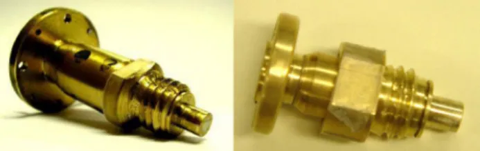
Fig. 2. Waveguide lens feeds for the Q-band (left) and for the V-band (right).
the lens can still be tested using separate waveguide feeds, each one designed for partial bands.
A broadband printed slot feed antenna with integral mixer presenting frequency stable linear polarization has already been developed and used by the authors for integrated lenses [16], [17]. However, the measurement setup available at our labo-ratory to test feeds with integral mixer cannot retrieve phase, which is of utmost importance in the present paper to assess the stability of the lens phase center.
So, alternatively, two waveguide feeds with equal radiation patterns were implemented: one in Q-band and another in V-band [24] (see Fig. 2). Both feeds have a tapered waveguide section loaded with dielectric material, ending in a narrow square aperture designed to present a good power transfer to the lens and produce a circular symmetric radiation pattern at the inner lens medium with about 8 dBi directivity. Its radiation pattern inside the lens is similar to that obtained by the classical uniplanar integrated double-slot feed, for the design frequency.
Although submillimeter integrated lenses are commonly made from very high dielectric permittivity materials like Alumina or Silicon, its mechanical hardness does not favor fabrication of larger lenses for millimeter waves by the milling technique available in our lab. No machinable material with comparable permittivity, low losses at millimeter waves and adequate size could be found, so the best approach was to use MACOR™ for the inner shell, a ceramic-based dielectric
ma-terial . Acrylic was used for the outer
shell ( . The complex permittivity
values of these materials were measured and confirmed using both a waveguide method and an open Fabry-Perot resonator method [25]. The adopted square root relation between the permittivity of the inner and outer shell materials maximizes the power transfer across the double-shell lens [26]. It was verified by simulations that even if the loss tangent of these alternative materials is high, the conclusions regarding the lens broadband performance in terms of beam width, Gaussissity, phase centre, polarization and internal reflections do not change for lower loss materials. Of course the described lens design procedure can be used with other combinations of existing dielectric materials, including loss tangent dielectrics that enable lens radiation efficiencies up to 95%.
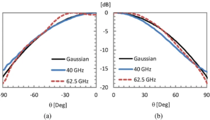
Fig. 3 presents the main planes power pattern from both waveguide feeds when radiating into unbounded MACOR™ medium. These simulated results were obtained with WIPL-D™ electromagnetic solver [27] based on the Method of
IEEE Proof
Web Version
4 IEEE TRANSACTIONS ON ANTENNAS AND PROPAGATION, VOL. 58, NO. 12, DECEMBER 2010
Fig. 3. Waveguide feeds simulated radiation pattern for an unbounded medium of MACOR: (a) E-plane; (b) H-plane.
Moments. Both feeds present similar axial-symmetric radiation power patterns, which can be approximated by a Gaussian curve
(12) with Gaussian width . The Gaussian curve is also superimposed on Fig. 3. An important figure of merit for radio astronomy applications is the Gaussicity of the antenna output beam [14] which measures how well the antenna couples to an incoming Gaussian beam. In the present case this value is influenced by the lens itself and by its feed radiation pattern. Gaussicity of the adopted waveguide feeds radiation pattern is of the order of 96%.
So, a Gaussian far-field power template was also adopted for in the lens design. The corresponding Gaussian width was adjusted to ensure an adequate illumination taper at the rim of the reflector as will be detailed in Section IV. All the lens design parameters are summarized in Table I. Given the selected values, the phase center position determined from (8) is mm, behind the lens base. The obtained lens profile is presented in Fig. 1 and a photograph of the manufactured proto-type is shown in Fig. 4. The waveguide feed is attached through an Archimedean screw to a threaded hole at an extended part of the base of the lens. This enables simple and reliable exchange of the test feeds without compromising alignment and measure-ment repeatability.
The magnitude of the lens input reflection coefficient mea-sured at the input port of each waveguide feed is presented in Fig. 5, which confirms an adequate match. Full-wave CST Mi-crowave Studio transient solver [28] simulations of the wave-guide radiating into a low-loss version of the lens and into un-bounded media of the same permittivity have shown that the reflection level at the waveguide port is mostly determined by the waveguide open-end mismatch (about dB). Lens in-ternal reflections originate negligible ripple on top of this level. So, lens internal reflections are low, but not because they are damped by material losses.
Magnitude and phase radiation pattern measurements were conducted at 40 GHz (with the Q-band waveguide) and at 62.5 GHz (with the V-band waveguide). The lens position in the setup was adjusted to make the waveguide aperture lie at the
Fig. 4. Fabricated lens prototype with inner shell of MACOR and outer shell of Acrylic.
TABLE I LENSDESIGNPARAMETERS
Fig. 5. Magnitude of the input reflection coefficient of the prototype lens when using the waveguide feed at: (a) Q-band; (b) V-band.
intersection of the chamber azimuth and roll positioner axes. The obtained results are presented in Figs. 6 and 7. The figures also show the corresponding simulated GO/PO results predicted by the ILASH tool [23], taking into account diffraction effects and first order internal reflections. Note that, in order to make the phase center characteristic more clear, the measured phase was subtracted by , which is equivalent to shifting the lens so that its rotation axes intersect at the GO predicted phase centre position . The represents the free space wave number.
The results from Figs. 6 and 7 show that at the main planes the lens magnitude radiation patterns are frequency stable. Mea-sured cross-polarization level is generally below dB. It was
IEEE Proof
Web Version
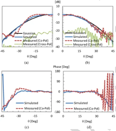
Fig. 6. Measured and simulated radiation pattern of the lens at 40 GHz: (a) E-plane magnitude; (b) H-plane magnitude; (c) E-plane phase; (d) H-plane phase.
Fig. 7. Measured and simulated radiation pattern of the lens at 62.5 GHz: (a) E-plane magnitude; (b) H-plane magnitude; (c) E-plane phase; (d) H-plane phase.
verified by simulation that the cross-polarization level in the di-agonal plane reaches dB. It is clear that the measured phase
Fig. 8. Simulated radiation pattern of the lens: (a) E-plane amplitude; (b) H-plane amplitude; (c) E-plane phase; (d) H-plane phase.
curve is almost constant within the main beam for both test fre-quencies and coincident for both planes, which translates into a well defined constant phase centre across the elevation angle , that is simultaneously coincident with the GO predicted value
mm.
The good agreement between measurements and simulations in Figs. 6 and 7 confirmed the validity of the ILASH GO/PO analysis. Actually, this tool has been thoroughly validated against measurements made on several canonical and shaped dielectric lenses [24], [29]. Therefore, the ILASH tool was used to evaluate the lens performance for the rest of the band from 30 to 90 GHz, assuming unchanged feed power pattern given by (12). Fig. 8 presents the lens radiation pattern simulated by ILASH, for different frequencies within the 100% bandwidth. As verified with the measurements for two far apart frequencies, the simulations also show frequency stable radiation patterns and phase center positions.
Fig. 9 shows the dB beam width as well as the lens di-rectivity dependence with frequency. Didi-rectivity is very stable along the bandwidth with oscillations of about dB. For com-parison, the directivity of a uniformly illuminated aperture in-creases by 9.5 dB from edge to edge of a 100% bandwidth. How-ever, the lens measured gain is not frequency independent due to the moderate dissipation losses associated with MACOR and Acrylic: in fact the measured gain is 9.9 dBi at 40 GHz while it is 6.4 dBi at 62.5 GHz, somewhat lower than the directivity values from Fig. 9. Dissipation losses depend on path length inside the lens normalized to the wavelength, thus introducing frequency dependence on gain. The effect of these losses could be minimized if Alumina and Fused Quartz were used instead.
IEEE Proof
Web Version
6 IEEE TRANSACTIONS ON ANTENNAS AND PROPAGATION, VOL. 58, NO. 12, DECEMBER 2010
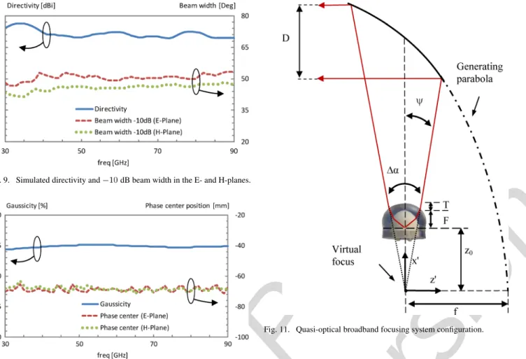
Fig. 9. Simulated directivity and010 dB beam width in the E- and H-planes.
Fig. 10. Simulated Gaussicity and phase center position in the E- and H-planes.
With loss tangent in the order of , the resulting radia-tion efficiency would range from 87% ( dB) to 95% ( dB) across the same bandwidth.
Fig. 10 shows the frequency dependence of the phase center position with respect to the lens base, which is quite stable. This result, along with the reasonably constant beam width versus frequency characteristic shown in Fig. 9, can ensure frequency independent reflector aperture efficiency. The same behavior was also observed in CST full-wave analysis of the lens fed by the integrated broadband printed slot feed from [16], [17]. The simulations were carried in the 30–50 GHz interval, limited by the large size of the lens (30 at 90 GHz, requiring 90 GB of RAM).
The Gaussicity [14] parameter allows evaluating the performance of the lens simultaneously in relation to the ampli-tude and phase center of the radiated field, since it measures it’s coupling to a Gaussian beam of the form
(13) where is the polarization unit vector, is a constant Gaussian width and is a phase parameter related to the phase center position
(14)
Fig. 11. Quasi-optical broadband focusing system configuration.
where is the wavelength in free space. Fig. 10 shows that the maximum Gaussicity of the lens output beam remains always
above 94% for constant and mm.
IV. LENSPLUSREFLECTORANALYSIS
In this section the results from the prototype lens are analyzed together with an offset parabolic reflector in order to evaluate the lens potential for broadband focal plane illumination with con-stant aperture efficiency. The geometry is specified in Fig. 11. The system is formed by an off-set parabolic reflector that is fed by the previously designed lens. The lens axis is at 90 with respect to the generating parabola axis (z -axis) and the lens is shifted up so that its phase center is coincident with the parabola focal point. Mechanical rotation of the reflector with respect to x -axis may be used for azimuth beam scan. The parabola focal length is m and the projected reflector aperture diam-eter is m; the reflector rim corresponds approximately to . The feed beam width was previously chosen as when defining , to ensure dB field taper at the rim.
The ILASH tool [23] was used to evaluate, through GO/PO, the reflector far-field radiation pattern when illuminated by the lens radiation pattern. For cross-check purposes, the reflector ra-diation pattern was also calculated using GRASP9 student edi-tion [30] when illuminated by a frequency constant Gaussian beam with . It is noted that the GRASP student edition version does not allow using external feeds. Main planes radiation patterns are presented in Fig. 12 for different frequen-cies in the 30 to 90 GHz frequency interval.
IEEE Proof
Web Version
Fig. 12. Reflector simulated radiation pattern. ILASH uses lens radiation pat-tern as feed; GRASP uses ideal Gaussian beam feed: (a) E-plane 30 GHz; (b) H-plane 30 GHz; (c) E-plane 50 GHz; (d) H-plane 50 GHz; (e) E-plane 70 GHz; (f) H-plane 70 GHz; (g) E-plane 90 GHz; (h) H-plane 90 GHz.
The reflector output beam width decreases with increasing frequency, as expected, since the lens produces an almost frequency independent illumination of the reflector surface. The slight difference between ILASH and GRASP results is explained by the difference in the feeds used in each tool.
Fig. 13. Directivity and aperture efficiency of the reflector.
Fig. 13 shows the output beam directivity versus frequency. It also shows the reflector aperture efficiency defined as the ratio between its effective area and the physical area
(15) where is the gain of the reflector along the direction of the peak of radiation. The gain of the reflector was calculated in a first step using the lens radiated power instead of the power at the lens feed port in order to rule out the effect of the dissi-pation losses associated with the lens materials and thus isolate the frequency behavior of the lens beamwidth, phase center po-sition and reflector aperture efficiency. The result is presented in Fig. 13, confirming the desired constant characteristic of , in the order of 78%. When dissipation losses from the MACOR and Acrylic prototype materials are included in the gain calcu-lation, the aperture efficiency ranges from 4% to 28% across the studied band. But for Alumina and Fused Quartz it ranges from 67% to 71%.
V. CONCLUSION
A new integrated lens antenna configuration was proposed with the objective to produce constant radiation pattern and phase center position across a very broad frequency band, in-tended for focal plane illumination of radio telescope reflector antennas with constant aperture efficiency across the band. This simple structure can compete with the complex assemblies of multiple split-band horns.
The two shaped refraction surfaces from the double shell lens configuration offer two degrees of freedom to enhance the output beam Gaussicity and to control the phase center position. Appropriate choice of the permittivity value from the two materials that form the lens shells enables a non-resonant broadband matching of the waves that impinge at the lens interfaces. This copes with the classical problem of lens in-ternal reflections originated by the need to use high permittivity dielectric materials to force the uniplanar feed radiation to couple strongly to the lens. The narrow-band matching layer is thus avoided. In part because the proposed lens design is based on GO, it has no frequency limitation as long as the
IEEE Proof
Web Version
8 IEEE TRANSACTIONS ON ANTENNAS AND PROPAGATION, VOL. 58, NO. 12, DECEMBER 2010
overall dimensions remain larger than the wavelength and the lens feed radiation pattern also remains constant and with good Gaussicity. The proposed lens configuration is ideal for integration with broadband coherent receivers like those using the hot electron bolometer, although these were not considered in the present study.
A lens prototype was fabricated and experimentally tested. Because the paper objective is just to prove the concept and not to explore the technological aspects of lens fabrication, some simplifying steps were taken, which do not preclude the in-tended demonstration: the prototype was designed to operate from 30 GHz to 90 GHz, two especial waveguide feeds with similar radiation pattern at two partial bands were used, and MACOR and Acrylic materials were used for lens fabrication instead of the common low loss but mechanically hard Alu-mina and Fused Quartz. Measured results have shown frequency stable radiation patterns with only dB of directivity variation across the bandwidth and a frequency stable phase center posi-tion located behind the lens, outside the lens body. Coupling of the lens radiation pattern with a Gaussian beam (Gaussicity) is better than 94% within the 100% bandwidth. Simulations in-cluding an off-set parabolic reflector showed almost frequency constant aperture efficiency ranging from 77.5% to 79% within the 1:3 bandwidth.
Although the excessive losses from MACOR and Acrylic ma-terials used in the lab prototype reduces significantly the system gain, dissipation losses do not otherwise affect the lens output beamwidth, Gaussissity or the phase center position, thus do not preclude the validation of the concept. In fact, both GO/PO and full-wave simulations have confirmed that these characteristics are maintained when losses are very low
which are typical for Alumina and Fused Quartz. There is no re-striction to redesign the lens with the same objective using any other combination of dielectric materials, including
loss tangent dielectrics that enable lens radiation efficiencies up to 95%.
ACKNOWLEDGMENT
The authors acknowledge the collaboration from V. Fred and C. Brito for prototype construction, and A. Almeida for proto-type measurements. The authors also thank M. van der Vorst for discussions on the general reflector plus lens configuration, the support from C. R. Medeiros with the measurement set-up and from Prof. R. Sauleau for facilitating some of the measurements at the IETR anechoic chamber.
REFERENCES
[1] A. Wootten and A. Thompson, “The Atacama large millimeter/submil-limeter array,” Proc. IEEE, vol. 97, no. 8, pp. 1463–1471, Aug. 2009. [2] D. Doyle, G. Pilbratt, and J. Tauber, “The Herschel and Planck space
telescopes,” Proce. IEEE, vol. 97, no. 8, pp. 1403–1411, Aug. 2009. [3] P. Siegel, “THz Instruments for space,” IEEE Trans. Microw. Theory
Tech., vol. 55, no. 11, pp. 2957–2965, Nov. 2007.
[4] A. Semenov, G. Gol’tsman, and R. Sobolevski, “Hot-electron effect in superconductors and its application for radiation sensors,” Supercon-duct. Sci. Technol., vol. 15, no. 4, pp. R1–R16, Apr. 2002.
[5] J. Gao, M. Hajenius, Z. Yang, J. Baselmans, P. Khosropanah, R. Barends, and T. Klapwijk, “Terahertz superconducting hot electron bolometer heterodyne receivers,” IEEE Trans. Applied Supercond., vol. 17, no. 2, pp. 252–258, Jun. 2007.
[6] L. Liu, Member, H. Xu, R. Percy, D. Herald, A. Lichtenberger, J. Hesler, and R. Weikle, “Development of integrated terahertz broad-band detectors utilizing superconducting hot-electron bolometers,” IEEE Trans. Applied Supercond., vol. 19, no. 3, pp. 282–286, Jun. 2009.
[7] A. Semenov, H. Richter, H. Hübers, B. Günther, A. Smirnov, K. Il’in, M. Siegel, and J. Karamarkovic, “Terahertz performance of integrated lens antennas with a hot-electron bolometer,” IEEE Trans. Microw. Theory Tech., vol. 55, no. 2, pp. 239–247, Feb. 2007.
[8] C. Bruns, P. Leuchtmann, and R. Vahldieck, “Comprehensive anal-ysis and simulation of a 1–18 GHz broadband parabolic reflector horn antenna system,” IEEE Trans. Antennas Propag., vol. 51, no. 6, pp. 1418–1422, Jun. 2003.
[9] K. Lee, C. Chen, and R. Lee, “UWB dual-linear polarization dielectric horn antennas as reflector feeds,” IEEE Trans. Antennas Propag., vol. 55, no. 3, pp. 798–804, Mar. 2007.
[10] C. Salema, C. Fernandes, and R. K. Jha, Solid Dielectric Horn An-tenna. Norwood, MA: Artech House, 1998.
[11] C. Granet, G. James, R. Bolton, and G. Moorey, “A smooth-walled spline-profile horn as an alternative to the corrugated horn for wide band millimeter-wave applications,” IEEE Trans. Antennas Propag., vol. 52, no. 3, pp. 848–854, Mar. 2004.
[12] H. Rudolf, M. Carter, and A. Baryshev, “The ALMA front end op-tics—System aspects and European measurement results,” IEEE Trans. Antennas Propag., vol. 55, no. 11, pp. 2966–2973, Nov. 2007. [13] R. Olsson, P. Kildal, and S. Weinreb, “The eleven antenna: A
com-pact low-profile decade bandwidth dual polarized feed for reflector an-tennas,” IEEE Trans. Antennas Propag., vol. 54, no. 2, pp. 368–375, Feb. 2006.
[14] G. Rebeiz, “Millimeter-wave and terahertz integrated circuit antennas,” Proc. IEEE, vol. 80, no. 11, pp. 1748–1770, Nov. 1992.
[15] A. Neto, “Planar implementation of the UWB leaky lens antenna,” in Proc. Int. Conf. on Electromagnetics in Advanced Applications, ICEAA’09, Sep. 2009, pp. 427–430.
[16] J. Costa and C. Fernandes, “Broadband slot feed for integrated lens antennas,” IEEE Antennas Wireless Propag. Lett., vol. 6, pp. 396–400, 2007.
[17] J. Costa and C. Fernandes, “Integrated imaging lens antenna with broadband feeds,” presented at the 2nd Eur. Conf. on Antennas Propag.—EUCAP, Edinburgh, U.K., Nov. 2007.
[18] S. Yeap, C. Parini, J. Dupuy, and M. Rayner, “FDTD simulation and measurement of a 90 GHz quasi-optical annular slot receiver,” IEE Proc.-Microw. Antennas Propag., vol. 152, no. 2, pp. 117–123, Apr. 2005.
[19] A. Neto, S. Bruni, G. Gerini, and M. Sabbadini, “The leaky lens: A broad-band fixed-beam leaky-wave antenna,” IEEE Trans. Antennas Propag., vol. 53, no. 10, pp. 3240–3246, Oct. 2005.
[20] M. van der Vorst, P. de Maagt, A. Netto, A. Reynolds, R. Heeres, W. Luinge, and M. Herben, “Effect of internal reflections on the radiation properties and input impedance of integrated lens antennas: Compar-ison between theory and measurements,” IEEE Trans. Microw. Theory Tech., vol. 49, no. 6, pp. 1118–1125, Sep. 2001.
[21] N. Nguyen, R. Sauleau, and C. Perez, “Very broadband extended hemi-spherical lenses: Role of matching layers for bandwidth enlargement,” IEEE Trans. Antennas Propag., vol. 57, no. 7, pp. 1907–1913, Jul. 2009.
[22] C. Fernandes, “Shaped-beam antennas,” in Handbook of Antennas in Wireless Communications, L. Godara, Ed. Boca Raton, FL: CRC Press, 2001.
[23] E. Lima, J. Costa, M. Silveirinha, and C. Fernandes, “ILASH—Soft-ware tool for the design of integrated lens antennas,” presented at the IEEE Antennas Propag. Soc. Int. Symp., San Diego, CA, Jul. 2008. [24] J. Costa, M. Silveirinha, and C. Fernandes, “Evaluation of a
double-shell integrated scanning lens antenna,” IEEE Antennas Wireless Propag. Lett., vol. 7, pp. 781–784, 2008.
[25] C. Fernandes and J. Costa, “Permittivity measurement and anisotropy evaluation of dielectric materials at millimeter-waves,” presented at the IMEKO World Congress, Lisbon, Portugal, Sep. 2009.
[26] M. Silveirinha and C. Fernandes, “Shaped double-shell dielectric lenses for wireless mm-wave communications,” in Proc. IEEE An-tennas Propag. Soc. Int. Symp., Salt Lake City, UT, Jul. 2000, pp. 1674–1677.
[27] B. Kolundzija, J. Ognjanovic, and T. Sarkar, WIPL-D Microwave: Circuit and 3D EM Simulation for RF & Microwave Applica-tions. Boston, MA: Artech House, Feb. 2006.
IEEE Proof
Web Version
[29] J. Costa, C. Fernandes, G. Godi, R. Sauleau, L. L. Coq, and H. Legay, “Compact Ka-band lens antennas for LEO satellites,” IEEE Trans. An-tennas Propag., vol. 56, no. 6, pp. 1251–1268, May 2008.
[30] GRASP9—Student Edition, [Online]. Available: http://www.ticra.com
Carlos A. Fernandes (S’86–M’89–SM’08)
re-ceived the Licenciado, M.Sc., and Ph.D. degrees in electrical and computer engineering from Instituto Superior Técnico (IST), Technical University of Lisbon, Lisbon, Portugal, in 1980, 1985, and 1990, respectively.
He joined the IST in 1980, where he is presently Full Professor in the Department of Electrical and Computer Engineering in the areas of microwaves, radio wave propagation and antennas. He is member of the Board of Directors from the research institute Instituto de Telecomunicações and coordinator of its Wireless Communications scientific area. He has been the leader of antenna activities in National and European Projects as RACE 2067—MBS (Mobile Broadband System), ACTS AC230—SAMBA (System for Advanced Mobile Broadband Applications) and ESA/ESTEC—ILASH (Integrated Lens Antenna Shaping). He has coauthored a book, a book chapter, and more than 120 technical papers in international journals and conference proceedings, in the areas of antennas and radiowave propagation modeling. His current research interests include dielectric antennas for millimeter wave applications, antennas and propagation modeling for per-sonal communication systems, RFID antennas, artificial dielectrics and meta-materials.
Eduardo B. Lima received the Licenciado and M.Sc.
degrees in electrical and computer engineering from Instituto Superior Técnico (IST), Technical Univer-sity of Lisbon, Lisbon, Portugal, in 2003 and 2008 respectively.
He is a Researcher at the Instituto de Telecomu-nicações, Lisbon, Portugal. From 2004 to 2007, he was involved in the ESA/ESTEC project ILASH (In-tegrated Lens Antenna Shaping). He is the coauthor of one patent application and six technical papers in international journals and conference proceedings in the area of antennas. His present research interests include dielectric lens an-tennas, UWB and MIMO.
Jorge R. Costa (S’97–M’03–SM’09) was born in
Lisbon, Portugal, in 1974. He received the Licen-ciado and Ph.D. degrees in electrical and computer engineering from the Instituto Superior Técnico (IST), Technical University of Lisbon, Lisbon, Portugal, in 1997 and 2002, respectively.
He is currently a Researcher at the Instituto de Telecomunicações, Lisbon, Portugal. He is also an Assistant Professor at the Departamento de Ciências e Tecnologias da Informação, Instituto Superior de Ciências do Trabalho e da Empresa. His present research interests include lenses, reconfigurable antennas, MEMS switches, UWB, MIMO and RFID antennas. He is the coauthor of four patent applications and more than 50 contributions to peer reviewed journals and international conference proceedings. More than ten of those papers have appeared in IEEE journals.