Abstract—A novel Quadruple-shaped Dielectric Resonator Antenna
(DRA) excited by a coaxial feed is investigated. The dielectric used
for investigation is biodegradable polymer based dielectric material
having a dielectric constant (�) of 3.45 and dielectric loss tangent
(δ) =0.02. The resulting antenna offers broad impedance bandwidth of 63.2% for |S11| < -10 dB from 2.8 to 5.2 GHz frequency band.
This antenna is suitable for practical use in WLAN (5.15–5.35 GHz)
and Wi-Max (3.4–3.69 GHz) applications. The results show the
peak gain of the antenna is 4.5dBi at resonant frequency 3.8 GHz.
It is also observed that the new proposed structure of
Quadruple-shaped DRA offers broadside radiation patterns and high efficiency
for the entire operating band. The simulated and experimental
results are well in agreement.
Index Terms— Biodegradable Polymer, Dielectric Resonator Antenna,
Quadruple-shaped DRA, Wi-Max,WLAN
I. INTRODUCTION
To enrich with new services to more users higher bit rate is indispensable that's why wireless
systems is shifting towards the microwave frequency bands with low interference and more available
bandwidth. However, at these frequencies, conductor loss is significant, which affects the gain and
efficiency of fabricated metallic antennas. For better utilization of microwave frequencies regarding
wireless applications, antennas with simple fabrication, higher efficiency, and larger impedance
bandwidth is statutory.
Dielectric Resonator Antennas (DRAs) have abundant captivating features such as wider impedance
bandwidth with higher radiation efficiency due to the deprivation of surface wave and conductor
Design of Biodegradable Quadruple
-
shaped
DRA for WLAN/Wi
-
Max applications
Pramod Kumar, Santanu Dwari,
Department of Electronics Engineering, Indian Institute of Technology (Indian School of Mines), Dhanbad, Jharkhand, India
[email protected]; [email protected]
Utkarsh
Department of Electronics and Communication, Inderprastha Engineering College, Ghaziabad, U.P., India [email protected]
Jitendra Kumar
losses [1]. Challenging part is a fabrication of DRAs as they are made of high permittivity ceramics,
which are naturally hard and extremely difficult to cut. The fabrication of these three dimensional
(3D) structures are onerous at microwave frequencies where the size of the antenna is reduced to the
millimeter or sub-millimeter range.
In recent years the most standard dielectric resonators (DRs) configurations such as rectangular,
hemispherical, cylindrical etc., have been modified in the pursuit of enhanced operational bandwidths
[2-7]. As compared to cylindrical or hemispherical DRA, Rectangular Dielectric Resonator Antenna
(RDRA) provides more degrees of freedom which can be used to control the impedance bandwidth of
the antenna [3].
Significant efforts with different techniques are adopted on DRAs such as Stacked DRs [8],
Multi-segment DRs [9], as well as more tortuous structures as see in [10-11] led to enhanced band widths of
about 35%–40%. In [12] stacked and embedded DRs also claimed the possibility to achieve
prodigious operational bandwidths up to more than 60%, but make the manufacturing process of
antenna complicated and expensive. The use of multiple resonating modes was adopted in [13]. More
recently a new class of DRA known as Super-shaped DRA [14] is introduced. These antennas render
freedom for the design of the DRs. Quadruple-shaped DRAs overt the good flexibility for matching
bandwidth and radiation patterns while preserving broadside radiation and ease of manufacturing.
In this paper a novel rectangular DRA based on Quadruple-shaped profile excited by a coaxial feed
is developed and investigated for WLAN/Wi-Max applications. The basic idea of proposed DRA is to
affiliate the use of biodegradable polymer based dielectric material which is easily available and
machinable materials. Biodegradable PLA for DRA material is special polymers which are made from
renewable resources instead of non-renewable petroleum based resources. This makes it relatively
cost efficient to produce. Biodegradable means it naturally degrades when exposed to the environment
after the use while during the use it will not decompose. It will help in managing the electronic waste
(e-waste) as it is becoming a huge concern. This choice helps us with inexpensive DRAs with
experimentally verified performance regarding broad impedance bandwidth, radiation stability and
radiation efficiency. It is found that the linear polarized proposed antenna offers 63.2% impedance
bandwidth for |S11| < -10 dB from 2.8 to 5.2 GHz. To authenticate the simulation, measurement was
carried out, and reasonable results are achieved.
II. ANTENNA DESIGN AND CONFIGURATION
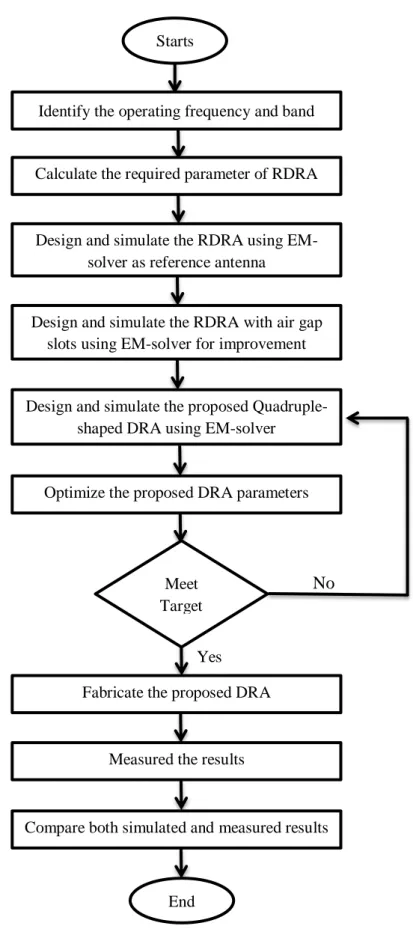
Design guide flowchart of proposed antenna is shown in Fig.1. The different views of the proposed
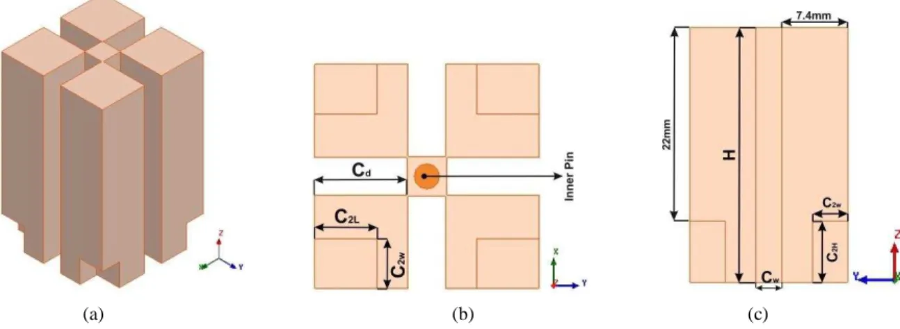
antenna are shown in Fig. 2, which is a simple a type of rectangular DRA. The designing of antenna is
done by using ANSYS HFSS [15] and validated with CST Microwave Studio [16] as well as
experimental measurements.
The dimensions of DRA along x-, and y-, directions are equal (length = width = 18mm) and along
ground plane level having characteristic impedance 50Ω. The radius of coaxial probe is Pr =1 mm and
height PH = 14 mm, as shown in Fig. 3 for RDRA. The strip size (length of one constituent) of the
Quadruple is taken as 7.4 mm.
Fig. 1 Design guide flowchart of proposed Quadruple-shaped DRA
Starts
Identify the operating frequency and band
Calculate the required parameter of RDRA
Design and simulate the RDRA using EM-solver as reference antenna
Optimize the proposed DRA parameters
Meet Target
Design and simulate the RDRA with air gap slots using EM-solver for improvement
Design and simulate the proposed Quadruple-shaped DRA using EM-solver
No
Fabricate the proposed DRA
Measured the results
Compare both simulated and measured results
(a) (b) (c)
Fig. 2 Proposed DRA geometry: (a) Isometric view, (b) Top view, (c) Side View
The theoretical formula for resonant frequency (��) of a RDRA is given as [1]:
��=2�√��√�2+ �2+ �2 (1)
where “�” is the dielectric constant of the RDRA, “c” is the speed of light in free space and symbol
“� ”, “� ” and “� ” represents the wave numbers in the x, y and z directions respectively. The
dielectric used for examination of DRA is polymer based ceramic material having a dielectric
constant (�) of 3.45 and dielectric loss tangent (�) =0.02. RDRA is braced by a square ground plane
as shown in Fig. 3. The ground plane of thickness GT = 1mm and sides GS = 100mm is made up by
copper.
(a) (b)
Fig. 3 Rectangular DRA as Reference Antenna: (a) Top View, (c) Side View
The development procedure of the Quadruple-shaped DRA includes three steps: First, a rectangular
shaped DR as (reference antenna) shown in Fig. 4(a) is taken and second, air gap slots [(Cw = 3.2mm)
x (Cd = 7.2 mm) x (H = 29 mm)] are inserted in it to reduce Q-factor as shown in Fig. 4(b). This DRA
is named as a modified antenna with side cut. Then to further modify the shape, cutting height (C2H),
cutting length (C2L), and cutting width (C2W) is done to achieve Quadruple-shaped DRA as shown in
Fig. 4(c).
The permittivity of the proposed antenna is altered with the perforated slots cut in the DRA and it
will become effective permittivity (εeff) of the DR with a smaller value. Thus, as the εeff decreases, the
Q factor decreases and hence the bandwidth is improved significantly. Hence, εeff of proposed DRA
0
r slots
eff
slots
V V
V V
(2)where V and Vslots are the volume of proposed DRA and air gap slots of DRA respectively.
(a) (b) (c)
Fig. 4 Evolutionary steps of Quadruple-shaped DRA: (a) Reference antenna, (b) Modified antenna with side cut, (c)
Proposed antenna
The main aim of research is to enhance the impedance bandwidth of DRA with effective cost which
can use for WLAN/Mi-Max applications. Carving out side’s portion also shifted the operating band in
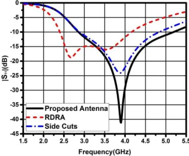
high frequency as well as improved the reflection coefficient. The comparison of reflection coefficient
versus frequency for Quadruple-shaped, RDRA and modified antenna with side cuts is shown in Fig.
5. The simulated results show that proposed antenna (Quadruple-shape DRA) is having a sharp
resonance dip of S11 is -41dB at 3.8GHz with 63.2% impedance bandwidth for |S11| < -10dB which is
highest as compared to RDRA and side cut DRA. The RDRA is having a resonant dip of S11 is -18dB
only at 2.7GHz with 53.3% fractional bandwidth for |S11| < -10 dB, whereas the resonant dip of S11 for
modified side cut DRA is -24dB at 3.8GHz.
Fig. 5 Reflection coefficient versus frequency for reference antenna (RDRA), modified antenna with side cuts and proposed
antenna (Quadruple-shaped)
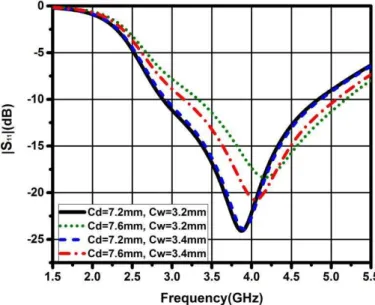
A parametric study is carried out to characterize the proposed DRA and the influence of various
for different cutting depth (Cd) is shown in Fig. 6. It is noticed that if cutting depth (Cd) is 7.2 mm and
cutting width (Cw) is 3.2 mm then antenna successfully enhances the bandwidth by 300 MHz with
respect to a reference antenna due to efficient impedance matching.
Fig. 6 Variation of reflection coefficient versus frequency curve for different value of cutting depth
In effort of further improvement of the result, the bottom edges of DR from all four sides are
engraved out, which successfully enhanced the bandwidth from 52.6% to 63.2%. To confirm this
parametric analysis, simulated reflection coefficient plot of the DRA versus frequency for different
value of cutting bottom edges is shown in Fig. 7. This analysis shows that cutting bottom edge not
only affects the impedance matching at the resonant frequency, but it also affects the impedance
bandwidth of the antenna. It is observed that the optimum impedance bandwidth is achieved by
choosing values for C2H = 8mm, C2L = 5mm and C2W = 4mm. Table I shows the comparison of the
proposed DRA with reference RDRA and side cuts DRA.
TABLE I: COMPARISON TABLE OF SIMULATED RESULTS OF DIFFERENT STRUCTURE
Parameters fr (GHz) BW (GHz) BW (%) Gain (dB)
RDRA 2.7 1.8 53.3 4.6
Side Cuts 3.8 2 52.6 4.3
Proposed DRA 3.8 2.4 63.2 4.5
BW– Bandwidth, fr– Resonant frequency
Fig. 8 shows the 3D gain pattern of proposed antenna at its resonant frequency 3.8GHz. The peak
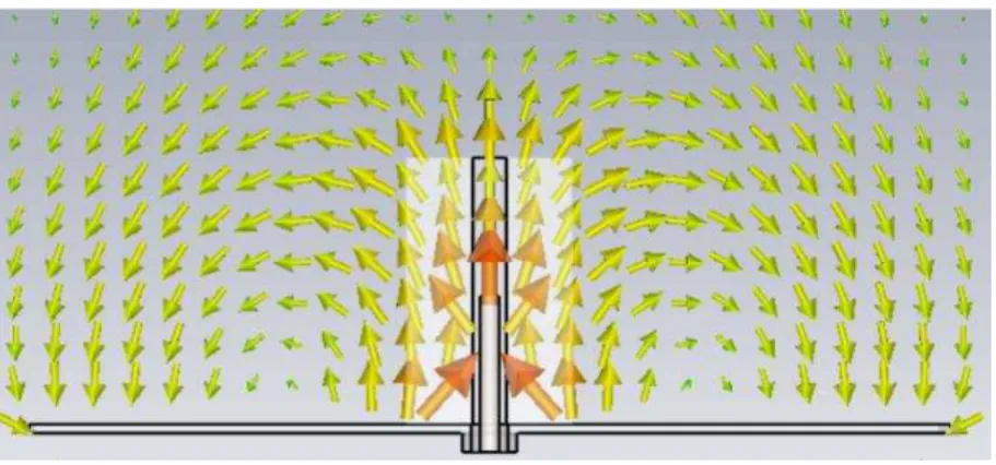
gain 4.5 dB is dignified at resonant frequency with broad side pattern. Fig. 9 shows the electric field
distribution in proposed DRA at its resonant frequency 3.8GHz. The field distribution clearly verifies
the presence of Quasi-TM111 like mode in reference to the corresponding cylindrical resonator mode
[18].
Fig. 8 3D gain pattern of proposed antenna at 3.8GHz
Fig. 9 Electric field distribution at 3.8GHz
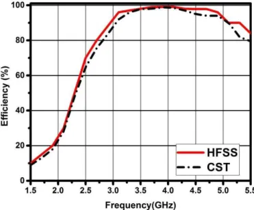
The comparison plot of radiation efficiency versus the frequency is shown in Fig. 10. The efficiency
of the DRA is more than 80% for complete band of operation i.e. 2.8 to 5.2 GHz. Radiated
efficiencies of the proposed antenna are in very good agreement with each other. Table II shows the
Fig. 10 Comparison of antenna efficiency as a function of frequency for Quadruple-shaped DRA
TABLE II: VALUE AND EXPANSION OF ABBREVIATIONS
Abbreviation Expansion Dimension (mm)
W DRA Width 18
H DRA Height 29
Gs Ground Plane Side 100
GT Ground Plane Thickness 1
Pr Pin Radius 1
PH Pin Height 14
Cw Side Cut Width 3.2
Cd Side Cut Depth 7.2
C2L Bottom Cut Length 5
C2H Bottom Cut Height 8
C2W Bottom Cut Width 4
III. COMPARATIVE STUDY
The comparative study is done to highlight the advantages of biodegradable polymer based DRA
over alumina (ceramic) based conventional DRA. The dimensions of both antenna i.e. polymer based
DRA and alumina based conventional DRA are considered same for comparison except the height.
The height and feed of the alumina based DRA is optimized to matche the resonance frequency. Here,
heigt = 25.3mm taken for alumina based DRA while 29mm used for proposed DRA. Fig. 11 shows
the comparative plots of reflection coefficient versus frequency and the variation of peak gain versus
frequency is shown in Fig. 12. It is observed that polymer based DRA achieves wider bandwidth
compare to alumina based DRA. It is also noticed that the peak gain over the operating band is remain
same. Except these entire advantage polymer based DRA have also many more benefits such as low
Fig. 11 Comparison of reflection coefficient versus frequency for the polymer based DRA and alumina based DRA
Fig. 12 Comparison of peak gain versus frequency for the polymer based DRA and alumina based DRA
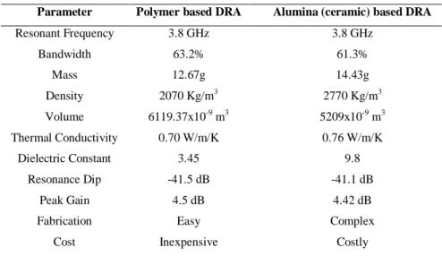
TABLE III: COMPARATIVE PARAMETERS FOR POLYMER AND ALUMINA BASED DRA
Parameter Polymer based DRA Alumina (ceramic) based DRA
Resonant Frequency 3.8 GHz 3.8 GHz
Bandwidth 63.2% 61.3%
Mass 12.67g 14.43g
Density 2070 Kg/m3 2770 Kg/m3
Volume 6119.37x10-9 m3 5209x10-9 m3
Thermal Conductivity 0.70 W/m/K 0.76 W/m/K
Dielectric Constant 3.45 9.8
Resonance Dip -41.5 dB -41.1 dB
Peak Gain 4.5 dB 4.42 dB
Fabrication Easy Complex
IV. EXPERIMENTAL RESULTS
The structure of proposed DRA is fabricated by additive manufacturing i.e. 3D printing (3DP). It is
a layer-by-layer approach of fabricating 3D objects. Commercially available SMA connector is used
to provide coaxial feed. Fig. 13 exhibits the fabricated DRA.
The reflection coefficient is measured using ROHDE & SCHWARZ, FSH8 handheld network
analyzer, while the radiation characteristics are measured using a basic antenna measurement setup.
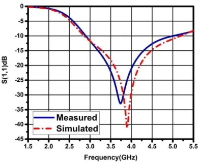
The comparison between simulated and measured variations of reflection coefficient versus frequency
for proposed DRA is shown in Fig. 14. The simulated results shows that the proposed DRA resonates
at 3.8 GHz, offering an impedance bandwidth of 63.2%, while the measured result shows that DRA
resonates at ~3.7 GHz, offering 64% impedance bandwidth for |S11| < -10 dB. Thus, simulated and
measured results are showing very good agreement across the operating band. The small difference in
the results is mainly due to the fabrication inconsistencies like air gaps between the DRA and the
ground plane, imperfections while drilling the hole for probe insertion, etc.
Fig. 13 Fabricated model of proposed DRA
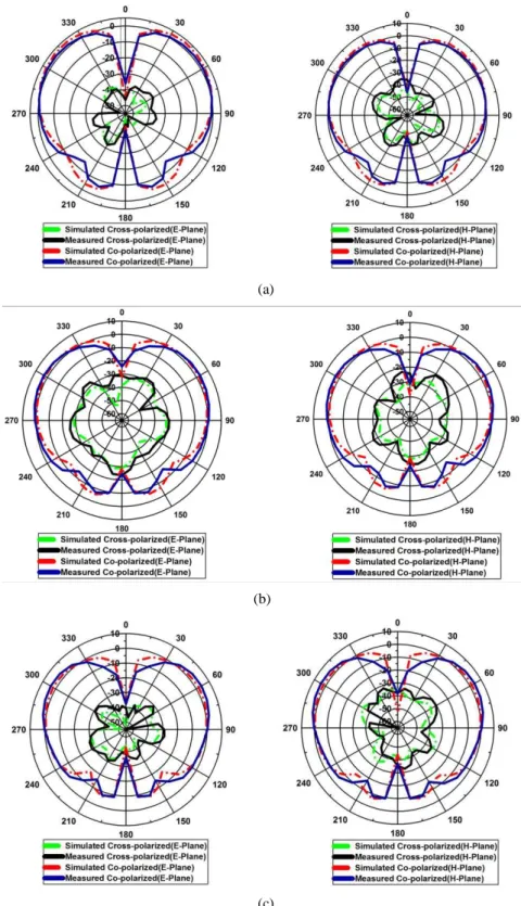
Antenna has been fed to radiate by the mean of coaxial cable. Fig. 15 shows the measured and
simulated co-polar as well as cross-polar radiation patterns in E-plane (phi=0) and H=plane (phi=90)
at frequencies 3.3, 3.8 and 4.4 GHz. It is clearly observed that cross-polar level is very lower than
co-polar level which verifies the linear co-polarization of antenna. The null in the boardside direction is
clearly visible for all radiation patterns, which verifies the presence of TM mode.
(a)
(b)
(c)
Fig. 15 Comparison of measured and simulated radiation patterns (E-Plane and H-Plane) of the proposed DRA: (a) 3.3 GHz,
The proposed antenna radiates conical beam pattern. In order to evaluate the uniformity received the
signal of all subscribers around the antenna, the radiation patterns in XY plane at the beam direction
with different theta angle (0o, 30o, 50o, 70o) is shown in Fig. 16. The main beam direction of the
pattern is found at angle ~50o. It is nearly omni-directional pattern with reference to polar plot for all
three selected frequency i.e. 3.3GHz, 3.8GHz and 4.4GHz.
Fig. 16 Simulated radiation patterns (XY-Plane) of the proposed DRA: (a) 3.3 GHz, (b) 3.8 GHz, (c) 4.4 GHz
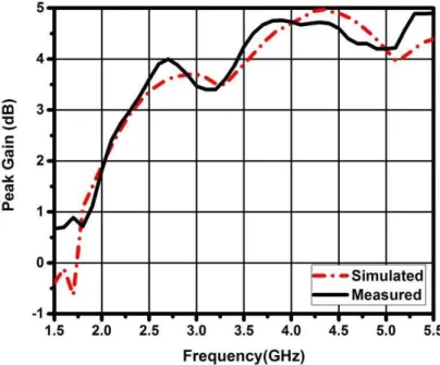
The comparison plot of measured and simulated variation of peak gain versus frequency is shown in
Fig. 17. The measured peak gain at 3.8 GHz is 4.6 dB while simulated peak gain at 3.8 GHz is 4.5dB.
It is also noticed that the gain is almost stable for the complete bandwidth of operation. Thus, the
proposed DRA offers lower losses and are comparable to the other regular geometries in the DRA
family. Table IV shows the judgment of the proposed DRA with the superlative cases of existing
inspects. It can be observed that the proposed antenna not only achieves wider bandwidth, but also
compact volume.
TABLE IV: COMPARISON OF THE PROPOSED STRUCTURE
Shape � V (10-6m3) BW (%) fr (GHz) Ref
Rectangular 9.8 13.5 56 3.2 19
Rectangular 10 6.54 32.6 4.6 20
Rectangular 9.8 9.39 33 3.9 21
Cylindrical 10 9.12 19.1 3.8 22
Tetraskelion 9.8 6.48 57.5 5.25 23
Quadruple-shaped 3.45 6.12 63.2 3.8 PS
�– Dielectric constant, V – Volume, BW – Bandwidth, fr– Resonant frequency, PS – Proposed Structure
V. CONCLUSION
A novel class of rectangular DRA along with Quadruple-shaped based geometry for biodegradable
polymer based material has been successfully implemented. This antenna has a simple-interesting
structure and relatively compact volume of 6.08cm3. The DRA resonates at 3.8 GHz, offering an
impedance bandwidth of 63.2% for |S11| < -10 dB from 2.8 to 5.2 GHz. Proposed DRA has many
more advantages over the conventional DRA such as low cost, easy fabrication, light weight and a
wider bandwidth. This makes the DRA suitable for practical use in the wireless communication
systems. Practical applications are like WLAN (5.15–5.35 GHz) and Wi-Max (3.4–3.69 GHz) system.
The peak gain of the DRA is 4.6 dB at the resonant frequency with high radiation efficiency. To the
best of our knowledge, such geometry has not been explored so far for a DRA. Thus, the varieties of
eco-designed DRA are possible by the adoption of polymer dielectric resonators with very effective
cost.
ACKNOWLEDGMENT
The authors would like to acknowledge Prof. Navneet Gupta, Head of the Department, Electrical &
Electronics Engineering, Birla Institute of Technology and Science, Pilani, Rajasthan, India and
Shailendra Singh, Deputy Engineer, Bharat Electronics Limited, India, for their support.
REFERENCES
[1] A. Petosa, “Dielectric resonator antenna handbook. Norwood, MA”, USA: Artech House, 2007.
[2] J. Kumar and N. Gupta, “Performance analysis of dielectric resonator antennas”, Wireless Personal Communications,
vol. 75, no 2, pp. 1029-1049, Mar. 2014.
[3] M. Lapierre, Y. M. M. Antar, A. Ittipiboon, and A. Petosa, “Ultra wideband monopole/dielectric resonator
antenna”, IEEE Microwave and Wireless Components Letters, vol. 15, no. 1, pp. 7–9, Jan. 2005.
[4] J. Kumar and N. Gupta, “Bandwidth and gain enhancement technique for Gammadion cross dielectric resonator
antenna” Wireless Personal Communications, vol. 85, no. 4, pp. 2309-2317, 2015.
[5] G. Drossos, Z. Wu, and L. E. Davis, "The air gap effect on a microstrip-coupled cylindrical dielectric resonator
antenna", Microwave and Optical Technology Letters, vol. 20, no. 1, pp. 36-40, Jan. 1999.
[6] J. Kumar and N. Gupta, “Linearly Polarized Asymmetric Dielectric Resonator Antennas for 5.2 GHz WLAN
[7] H. Nawaz, and M. Ali Babar Abbasi. "Wide‐band dielectric resonatorantenna using K‐shaped fractal", Microwave and
Optical Technology Letters, vol. 58, no.6, pp. 1504-1507, 2016.
[8] A. A. Kishk, X. Zhang, A. W. Glisson, and D. Kajfez, “Numerical analysis of stacked dielectric resonator antennas
excited by a coaxial probe for wideband applications”, IEEE Transactions on Antennas and Propagation, vol. 51, no. 8,
pp. 1996–2006, Aug. 2003.
[9] A. Petosa, N. Simons, R. Siushansian, A. Ittipiboon, and M. Cuhaci, “Design and analysis of multisegment dielectric
resonator antennas”, IEEE Transactions on Antennas and Propagation, vol. 48, no. 5, pp. 738–742, May 2000.
[10]A. A. Kishk, Y. Yin, and A. W. Glisson,“Conical dielectric resonator antennas for wide-band applications”, IEEE
Transactions on Antennas and Propagation, vol. 50, no. 4, pp. 469–474, Apr. 2002.
[11]A. A. Kishk, “Wide-band truncated tetrahedron dielectric resonator antenna excited by a coaxial probe”, IEEE
Transactions on Antennas and Propagation, vol.51, no. 10, pp. 2913–2917, Oct. 2003.
[12]A. G. Walsh, C. S. De Young, and S. A. Long, “An investigation of stacked and embedded cylindrical dielectric
resonator antennas”, IEEE Antennas and Wireless Propagation Letters, vol. 5, pp. 130–133, Jan. 2006.
[13]C. S. De Young and S.A. Long, “Wideband cylindrical and rectangular dielectric resonator antennas”, IEEE Antennas
and Wireless Propagation Letters, vol. 5, pp. 426–429, Oct. 2006.
[14]M. Simeoni, R. Cicchetti, A. Yarovoy, and D. Caratelli, “Supershaped dielectric resonator antennas”, IEEE
International Symposium on Antennas and Propagation Society (APSURSI'09), Charleston, SC, pp. 1-4, Jun. 2009.
[15]Ansys, H. F. S. S. "ver. 15.0, ANSYS" Inc., Southpointe 275.
[16]CST Microwave Studio. Computer Simulation Technology, Framingham, MA, USA, 2015.
[17]S. Fakhte, H. Oraizi, and R. Karimian, “A novel low cost circularly polarized rotated stacked rectangular dielectric
resonator antenna”, IEEE Antennas and Wireless Propagation Letters, vol. 13, pp. 722-725, 2014.
[18]L. Zou, “Dielectric resonator antennas from multifunction microwave devices to optical nano-antennas”, Ph.D. Thesis,
School of Electrical and Electronic Engineering, University of Adelaid, Australia, March 2013.
[19]J. Kumar and N. Gupta, “Investigation on Rudimentary Geometries of Dielectric Resonator Antenna”, The 36th
Progress In Electromagnetics Research Symposium Proceedings (PIERS 2015), Prague, Czech Republic, pp.
2149-2152, July 2015.
[20]Y. F. Wang, T. A. Denidni, Q. S. Zeng, and G. Wei, "Band-notched UWB rectangular dielectric resonator antenna",
Electronics Letters, vol.50, no.7, pp.483,484, March 27, 2014.
[21]J. Kumar, and N. Gupta, “Investigation on microwave dielectric materials for dielectric resonator antennas”,
International Journal of Applied Electromagnetics and Mechanics, vol. 47, no. 1, pp. 263-272, 2015.
[22]L. F. Zou, D. Abbott, and C. Fumeaux, “Omnidirectional cylindrical dielectric resonator antenna with dual
polarization”, IEEE Antennas and Wireless Propagation Letters, vol. 11, pp. 515–518, 2012.
[23]J. Kumar, B. Mukherjee, and N. Gupta, “A Novel Tetraskelion Dielectric Resonator Antenna for Wideband