Abstract
The propagation of compaction waves in a stationary foam block subjected to an impact by a small mass is studied in order to examine the mechanism of compaction within the primary and reflected stress waves. The analysis is focused on aluminium strain rate insensitive foam that exhibits strain hardening under quasi-static compression. A theoretical approach is applied using a uni-axial model of compaction in which the compacted strains, being functions of the velocity variation, are not predefined but are obtained as a part of the solution. The present approach allows one to obtain the strain histories and strain distributions within the primary compaction wave as well as within the reflected wave, which propagates in a media with non-uniform density increasing monotonically in the direction of loading. FE simulations consider-ing aluminium based foam Cymat with density 411.5 kg/m3 are carried out in order to verify the proposed theoretical model. A comparison between the impact velocity attenuation predicted by the present model and classical Rigid Perfectly-Plastic Locking material model for cellular materials is discussed.
Keywords
Compaction waves, Reflected wave, Aluminium foam, Impact, Semi-analytical model
Primary and Reflected Compaction Waves in a Foam Rod Due
to an Axial Impact by a Small Mass
1 INTRODUCTION
The light weight and enhanced energy absorption capacity of cellular materials with different topol-ogies under dynamic loading make these materials attractive for various applications. Therefore efforts are made to develop models of the dynamic compaction when introducing various simplifica-tions. Despite the similar common characteristic of an extended strain region with slowly varying stresses, different mechanisms of compaction develop depending on the material topology. A distinc-tion can be made between cellular materials which exhibit local softening during the response, as
D. Karagiozova a M. Alves b
a Institute of Mechanics, Bulgarian
Acad-emy of Sciences,
Acad. G. Bonchev St., Block 4, Sofia 1113, Bulgaria
b Department of Mechatronics and
Me-chanical Systems Engineering, University of Sao Paulo, Sao Paulo 05508-900, Brazil [email protected]
http://dx.doi.org/10.1590/1679-78251300
Latin American Journal of Solids and Structures 12 (2015) 905-924
honeycombs under out-of-plane impact, and open and closed cellular materials, which exhibit main-ly hardening during the quasi-static compression. While the first class of materials is characterized by inertia sensitivity and stress increase proportional to the impact velocity, the latter class of ma-terials is characterized by a dynamic stress enhancement proportional to the velocity squared. Therefore the majority of the theoretical efforts to characterize the cellular materials are focused on the second class.
A shock wave propagation model in cellular materials was proposed by Reid and Peng (1997) to explain the crush enhancement of wood specimens assuming a rigid perfectly-plastic locking (RPPL) mechanism. A thermo-mechanical approach was used in the formulation of the dynamic compaction process to provide a first-order understanding of two impact scenarios (Tan et al., 2005a) supported by the experimental observation of compaction of low density open cell material (Tan et al., 2005b). Retaining the basic characteristics of the one dimensional shock wave models, more detailed materi-al models were used to account for the elastic materimateri-al properties. An elastic-plastic model with hardening was proposed by Harrigan et al. (2005) while an elastic perfectly-plastic-with rigid lock-ing model was applied by Lopatnikov et al. (2004). Although different material models were as-sumed, a predefined strain value associated with the fully locked material was used. A summary of different boundary conditions for a uniaxial foam compaction was presented by Main and Gazonas (2008).
While the classical RPPL material model is appropriate and easy to apply for the approximation of the stress-strain characteristic of a cellular material with negligible strain hardening, the majority of higher density cellular materials exhibit strain hardening. The latter becomes significant with the increase of the material density. In order to apply the RPPL model to these materials different def-initions of the densification strain have been proposed based on homogeneous material properties (Tan et al., 2005a; Lopatnikov et al., 2004) and based on the cellular topology (Hu and Yu, 2010), all of them being used over the entire range of the velocities, which occur during the impact event. However, a full compaction within the primary stress wave cannot always be achieved in foam materials exhibiting strain hardening, as shown experimentally by Pattofatto et al. (2007). Tan et al. (2012) also reported experimental results on dynamic compaction of Duocell foam pointing out the dependence of the maximum compaction strains on the impact velocity. In order to analyze the foam compaction under moderate velocity impact, a uniaxial rigid-linear hardening-locking model was proposed by Zheng et al. (2012), which can predict compaction strains that are smaller than the locking strain. A uniaxial shock model, also using a constitutive relation with plastic hardening for cellular materials, was proposed by Zheng et al. (2013) to analyze the compaction under decreas-ing velocity. The numerical simulations usdecreas-ing Voronoi open cell material model and closed-cell foam showed close agreement with the predictions of the analytical model.
Latin American Journal of Solids and Structures 12 (2015) 905-924
Therefore, the concept of a predefined densification strain is not applicable to the analysis of foam materials subjected to a load with a varying velocity or materials with strain hardening. This is particularly true when the applied velocity is a rapidly decreasing function of time, for example the velocity attenuation in a cellular material subjected to a small mass impact (Karagiozova et al., 2012).
Despite the different stress-strain curve approximations, the pre-defined locking strain is the common characteristic of many of the proposed material models. Differently, a model based on a power-law hardening stress-strain characteristic of the foam was used by Pattofatto et al. (2007) to estimate the level of compaction strains due to a constant velocity impact. A more realistic impact scenario when the velocity decreases with time was analyzed in a series of studies by Karagiozova et al. (2010, 2012, 2013, 2014). The proposed approach allowed determining a non-uniform strain dis-tribution behind the wave front with sufficient accuracy. A strong dependence of the strains on the impact velocity within the compacted regions was revealed in these studies.
The commonly used assumption of a locking strain in the theoretical models limits the analysis to the propagation of the primary compaction wave as these models have no capability to deal with a secondary compaction. A simplified model of the propagation of the reflected wave from the layer interface was proposed in (Karagiozova and Alves, 2014) when assuming a nearly constant density caused by the primary wave. However, a secondary compaction due to the reflected wave within a media having a non-uniform foam density, which occurs during the impact by a small mass, has not been examined.
In this paper, the unified approach for dynamic compaction of a class of cellular materials with strain hardening proposed in the previous studies (Karagiozova et al., 2010, 2012, 2013) is extended in order to apply it to the foam compaction within the wave reflected from a stationary boundary of a foam block. The latter compaction is considered as a wave developing in a media with non-uniform initial density which increases monotonically in the direction of loading. Numerical simula-tions are carried out to verify the results from the theoretical model. An analysis of the mechanism of compaction within the reflected wave can help to estimate the additional portion of the absorbed energy as well as the force transfer at the distal end of a stationary foam block.
2 THEORETICAL MODEL
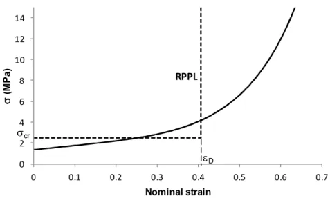
No details of the cellular topology are considered in the present study and it is assumed that the analyzed class of foam materials can be modeled as a homogeneous material which exhibits strain hardening. The stress-strain dependence for the examined foam is characterized by a strictly con-cave curve which has a general expression
,
g
g
0
,
Y (1)Latin American Journal of Solids and Structures 12 (2015) 905-924
2.1 Primary compaction wave
Consider the case when a stationary foam block is subjected to an impact by a small mass with initial velocity. The velocity of the mass is attenuated during the response due to the energy ab-sorbed by the plastic deformation of the foam. In this case, a plastic unloading wave starts to prop-agate if the applied load causes stresses exceeding the elastic limit of the material. This is a wave of strong discontinuity characterized by discontinuous velocity, stress, strain and density on the wave front while the particles behind the plastic wave front experience elastic unloading (Nowacki, 1978). An elastic precursor wave starts to propagate ahead of the plastic wave front.
Generally, if a plastic unloading wave propagates from region B (behind the wave front) to re-gion A (ahead of the wave front), the conditions through the front of discontinuity, the conserva-tion of mass and momentum conservaconserva-tion, are (Nowacki, 1978)
A
B
B
A
G
V
G
V
,
B
A
B
G
V
B
V
B
V
A
. (2a,b)In Eqs (2),
A,
V
A and
B,
V
B are the characteristic parameters ahead of and behind the wavefront, respectively and is the speed of the wave front.
Since the elastic strains are much smaller than the plastic strains due to compaction, the elastic strains in the deformed foam material behind the front of the unloading wave can be neglected and a rigid unloading can be assumed. The continuity equation in the region of unloading (along the coordinate
) is formulated as
Bdt
BdV
d
d
(3)0 2 4 6 8 10 12 14
0 0.1 0.2 0.3 0.4 0.5 0.6 0.7
s
(M
P
a
)
Nominal strain
eD
scr
RPPL
Latin American Journal of Solids and Structures 12 (2015) 905-924
which leads to
dV
d
0
behind the wave front thus defining a rigid body motion of the com-pacted region. The particle velocity,V
, is independent of
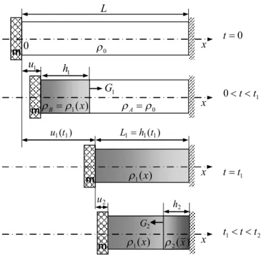
and equal to the particle velocity of the wave front.Schematic of the propagation of the primary and reflected wave in a finite length foam rod when impacted by a mass is shown in Figure 2.
Figure 2: Schematic of the propagation of primary and reflected wave in a finite thickness foam block.
The characteristic variables just behind the primary wave front are
B
B
d B B
B
V
V
V
,
1,
,
01
(4a-d)
while just ahead of the wave front
0
,
,
0
,
0
qs Y AA A
A
V
(5a-d)when neglecting the material elasticity.
The equations of motion, which describe the propagation of the primary compaction wave during the time interval , are (Karagiozova et al., 2012)
(6a)
t0
0tt1
tt1
t1tt2 m
m
m
0
A
) (
1 x
B
1
G
) (
1 x
) (
1 x
2(x)
2
G
m
)
(1
1t
u L1h1(t1)
1
h
1
u
2
h
2
u
x
x
x
0
L
x 0
1
0
t
t
)
(
1
1 2
0 1
1
0
V
V
h
u
m
dt
dV
Y
Latin American Journal of Solids and Structures 12 (2015) 905-924
, , (6b-d)
where are the velocity and displacement of the rigid mass, is the thickness of the compacted zone and is the mass per unit area of the striker; is the compaction strain and is the Lagrangian speed of the primary compaction wave (Figure 2). The ini-tial conditions are
0
)
0
(
)
0
(
,
)
0
(
V
0h
1
u
1
V
(7)and for . The strain behind the wave front is non-uniform and taking into
account the mass conservation law within the compacted region , a relationship between the initial density of the foam, and density in this region can be obtained
) (
0
1 1 0
1t h
t
u
t
h
d
(8)Making use of the unique stress-strain relationship of the analyzed foam, a relationship can be obtained based on the possibility that the pairs of variables that provide equivalent representation of the Hugoniot curve can be transformed to any of the other possible representations using the jump conditions (Davison, 2008)
1/20
1
V
(9)Details of the calculation of the function are presented in Karagiozova et al. (2012). For the particular foam material, the relationship
1
F
1e
V
is best approximated by a function with the following general expression
1
F
1e
V
a
1exp
b
1
V
c
1
d
1 (10)and coefficients a1 =116.888449, b1 =-0.607876m/s, c1=72.314379m/s and d1 =-115.921474.
2.2 Reflected Compaction Wave
The impact of a small mass on a foam rod causes non-uniform strains behind the primary com-paction wave, which decrease rapidly with the distance propagated by the wave during the time interval . A reflected wave can occur from the stationary end at and develop for . Since a rigid unloading was assumed behind the primary compaction wave, it can be
antic-ipated that at , the entire foam rod with length has velocity .
The secondary compaction will develop in a foam rod, which is characterized by a non-uniform initial density , ( ) monotonically increasing in the direction of loading (positive
1 1
1
1
V
dt
dh
1 1
1
V
G
V
t
dt
du
1
)
(
),
(
t
u
1t
V
h
1(
t
)
m
1
V
11
G
)
(
)
(
t
u
1t
u
0
t
t
1
t
h
10
1
F
1e
V
V
F
1e1
0
t
t
t
t
11
t
t
1
t
t
L
1
h
1(
t
1)
V
(
t
1)
)
(
1
x
Latin American Journal of Solids and Structures 12 (2015) 905-924
density gradient). Examples of the material characteristic are shown in Figure 3a for the analyzed Cymat foam when subjected to impacts with initial velocity of 100 and 200 m/s, m = 18.997 kg/m2. The initial material strength at is assumed to correspond to the attained
density so that it can be defined as , .
The strains along the foam thickness at , when the second deformation phase com-mences, are equal to zero due to the assumption of rigid unloading during the propagation of the primary wave.
)
(
1
x
1
t t
)
(
1
x
1Y(
x
)
1(
x
),
t
1
1(
x
)
0(
1
1(
x
,
t
1))
)
(
2
x
t
t
10 400 800 1200 1600
0 0.02 0.04 0.06 0.08 0.1 0.12
r0
,
r1
(k
g
/m
3)
x (m)
V0= 100 m/s
V0= 200 m/s
Initial density Stationary end
(a)
Figure 3 (a):Material characteristics at the time of initiation of the reflected wave (tt1); (a) density distributions for
V
0= 100 and 200 m/s.0 10 20 30 40 50 60
0 0.2 0.4 0.6 0.8
s
,
s1
(M
P
a
)
Nominal strain
s1(x = 0) Stationary end
s1(x = L1) s1(x1) s1(x2)
Initial stress-strain curve
Figure 3 (b): Material characteristics at the time of initiation of the reflected wave (tt1);
Latin American Journal of Solids and Structures 12 (2015) 905-924
The values of and at are used as characteristics of a material with non-uniform density during the second deformation phase. Since the functions and
vary monotonically with , they can be approximated by continuous analytical functions. The stress-strain relationship at each cross-section of the foam can be obtained from the original
curve when shifting the origin of the curve at . The
stress-strain curves at several cross-sections ( ) are
shown in Figure 3b for a 200 m/s impact.
A rigid unloading behind the reflected wave is assumed similarly to the propagation of the prima-ry wave. The characteristic variables just behind the front of the reflected wave are
,
(
)
1
(
)
,
)
(
,
0
2x
1V
1x
2x
V
B
B
B
d
B
(11a-d)while just ahead of the wave front
)
(
),
(
),
,
(
,
1x
t
1 1 1x
1x
V
V
A
A
A
qs
Y
A
(12a-d)when neglecting the material elasticity. In Eq. (11c),
V
Yx
x
V
x
V
d
,
)
(
)
(
2 2 1 11
(13)The equations of motion with respect to the velocity of the rigid mass and displacement during can be obtained from the momentum conservation
,
2(
)
0 2(
2)
,
2(
)
2(
)
2(
)
1
x
V
dt
d
m
L
m
l
V
l
t
u
t
h
t
d
(14)where is the dynamics stress behind the wave front and is the mass per unit area of the new deformed portion near to the stationary end.
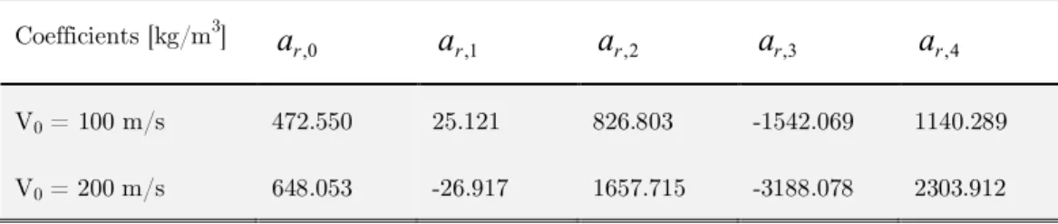
Let us assume that the density along the foam rod, can be approximated by the follow-ing polynomial function
,
(
0
,
),
4
)
,
(
)
(
1 10 , 1
1
1
n
L
x
L
x
a
t
x
x
k n k i r
(15)where coefficients have a dimension of density. Then
4 1 2 4 , 3 1 2 3 , 2 1 2 2 , 1 2 1 , 0 , 2 2 25
4
3
2
)
(
L
l
a
L
l
a
L
l
a
L
l
a
a
l
l
m
r r r r r(16)
The new deformed part has length measured from the stationary end,
and being the displacement of the moving end and the thickness of the second compacted zone, which develops from the stationary end (Figure 2). Equation (14) can be presented in the form
)
(
1
x
1Y(
x
)
t
t
1)
(
1
x
1Y(
x
)
x
)
(
2(
x
)
(
x
,
t
1)
1(
x
,
t
1)
)
,
(
2*
1
Yx
1 2 1*
,
,
,
0
x
x
L
x
0
x
1
x
2
L
1) (t V
)
(
2t
u
t
t
1
,
2(
)
1
x
V
d
m
2(
l
2)
)
(
1x
i ra
,)
(
)
(
)
(
2 22
t
u
t
h
t
l
u
2(
t
)
)
(
2
t
Latin American Journal of Solids and Structures 12 (2015) 905-924
x
V
m
L
m
l
V
m
l
V
d
)
(
)
(
)
(
,
2 0 2 2 2 21
,)
,
(
2 2V
x
V
l
. (17a,b)Substituting Eqs. (13), (16) and (17b) into Eq. (17a), the following equations of motion with
re-spect to , and are obtained
)
(
)
(
2 2 0 1l
m
L
m
x
dt
dV
Y
, (18a)
)
(
)
(
1
2 2 2 2 2l
l
V
dt
dh
,)
(
)
(
1
)
(
2 2 2 2 2 2l
l
V
l
G
,V
t
dt
du
2 (18b,d)
where is the compaction strain within the reflected wave and (Figure
2) is the Eulerian wave speed of the compaction wave. The initial conditions for the second de-formation phases which commences at are
0
)
0
(
)
0
(
),
(
)
0
(
V
t
1h
2
u
2
V
. (19a,b)The total displacement of the rigid mass during this deformation phase is
)
(
)
(
)
(
t
u
1t
1u
2t
u
. (20)Note that strains obtained during the second deformation phase are added to the strains obtained during Phase 1 and the total final strains are obtained as
)
(
)
(
)
(
x
1x
2x
. (21)Similarly to the propagation of the primary compaction wave, a relation between the strain jump and the velocity jump can be obtained, which is characteristic at each material point .
There-fore the strain jump can be expresses as . The particular form of this
func-tion depends on the foam properties and the stress state attained at the end of the first defor-mation phase ( ). The governing nonlinear ordinary differential equations (6) and (18) are solved numerically when using Maple 17.
3 NUMERICAL MODEL
Numerical simulations are carried out to verify the one-dimensional theoretical model of foam compaction when analyzing the deformation of a block with diameter 0.05 m and thickness of 0.11 m. An initial impact velocity is prescribed to the impacting mass. Due to the symmetry of the problem a quarter of the foam block is modeled. The velocity and corresponding dis-placements of the rigid mass are recorded.
The crushable foam model with volumetric hardening available in ABAQUS/Explicit (ABAQUS 6.11) was used for the foams. Elastic modulus of 5 GPa is used in the simulation to
)
(t
V
h
2(
t
)
u
2(
t
)
l
2 2
l
2,
V
2
G
2(
l
2)
1
t
t
)
(
2x
x
2(
x
)
F
2e
V
,
x
Latin American Journal of Solids and Structures 12 (2015) 905-924
diminish the influence of the elastic deformations. The stress strain curve for Cymat foam (alu-minium based closed cell foam) with density 411.5 kg/m3 (Langdon et al., 2010) is shown in Fig-ure 1.
Solid elements were used to model the foam when an automatic meshing was applied in the (y,z) plane with a maximum element length equal to the element thickness in the x direction. The mesh sensitivity analysis was carried out with respect of the variation of the distances of propaga-tion of the compacpropaga-tion waves, thicknesses of the compacted zones, and , longitudinal displacements, and , and nominal strains. It was established that the mesh refinement with element thickness smaller than 2 mm has only a marginal effect on the analyzed variables. Elements with thickness of 0.74 mm in the x-direction were used in the present analysis.
4 EXAMPLES AND DISCUSSION
4.1 Comparison between the theoretical approach and numerical simulations
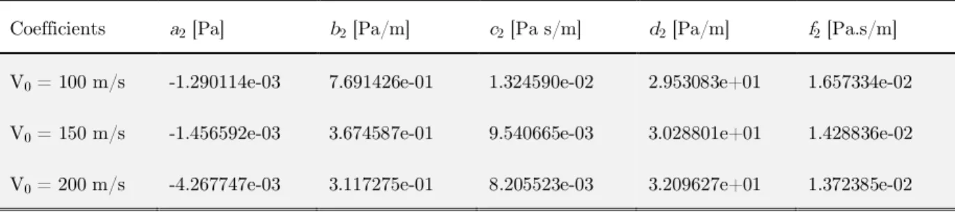
The response of a foam block to a mass impact is analyzed for initial velocities between 50 and 200 m/s. For the selected foam configuration a secondary compaction can occur due to the re-flected wave, which develops from the stationary end. During Phase 2, the dependence is approximated by the function
V
f
x
d
V
c
x
b
a
V
x
2 2
2 2 2 2
1
)
,
(
(22)where . The values of the coefficients in Eq (22) are given in Table 1
for = 100, 150 and 200 m/s. The strength variation at , which corresponds to the varia-ble density, , attained by the foam at this time instance is approximated by the function
s ss
Y
c
L
x
b
L
x
a
x
1 1 1
1
)
(
. (23)The coefficients of the functions, which approximate and , are presented in Tables 2 and 3, respectively.
Coefficients a2[Pa] b2[Pa/m] c2[Pa s/m] d2[Pa/m] f2[Pa.s/m]
V0 = 100 m/s -1.290114e-03 7.691426e-01 1.324590e-02 2.953083e+01 1.657334e-02
V0 = 150 m/s -1.456592e-03 3.674587e-01 9.540665e-03 3.028801e+01 1.428836e-02
V0 = 200 m/s -4.267747e-03 3.117275e-01 8.205523e-03 3.209627e+01 1.372385e-02
Table 1: Coefficients in Eq. (22) ( ) for different impact velocities.
)
(
1
t
h
h
2(
t
)
)
(
1
t
u
u
2(
t
)
)
,
(
2
x
V
u
2h
2
,
x
[
0
,
L
1]
x
0
V
t
t
1)
(
1
x
)
(
1
x
1Y(
x
)
)
,
(
2V
x
Latin American Journal of Solids and Structures 12 (2015) 905-924
Coefficients [kg/m3]
V0 = 100 m/s 472.550 25.121 826.803 -1542.069 1140.289
V0 = 200 m/s 648.053 -26.917 1657.715 -3188.078 2303.912
Table 2: Coefficients in Eq. (15) ( ) for initial impact velocities of 100 and 200 m/s.
Coefficients [Pa] [Pa]
V0 = 100 m/s 9.234171e+05 -8.727554e-01 1.898423e+06
V0 = 200 m/s 2.626587e+06 -8.750500e-01 3.6508126e+06
Table 3: Coefficients in Eq. (23) ( ) for initial impact velocities of 100 and 200 m/s.
Velocity attenuations as functions of the displacement of the rigid mass are shown in Figure 4 for several impact velocities where the thick lines represent the results from the theoretical ap-proach based on Eqs (6) and (18). The dashed parts of these lines correspond to the velocity at-tenuation due to the reflected wave as predicted by the theoretical model. The thin lines show the results from the numerical simulations. Good agreement between the two sets of results is ob-served.
0 ,
r
a
a
r,1a
r,2a
r,3a
r,4)
(
1x
s
a
b
sc
s)
(
1Yx
u
Figure 4: Velocity attenuations as functions of the displacement of the rigid mass; the thick and thin lines represent the theoretical and numerical results, respectively, the dashed lines show the velocity attenuation due to the reflected wave (Eqs. (18)).
0 50 100 150 200
0 0.01 0.02 0.03 0.04 0.05 0.06 0.07
V
(
m
/s
)
u (m)
Latin American Journal of Solids and Structures 12 (2015) 905-924
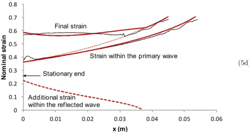
The strain variation during the response is the major parameter which, together with the corre-sponding dynamic stress, determines the energy absorption of the foam and force transfer to the opposite end of the finite thickness block. The strain distributions at the end of the two phases of deformation are shown in Figures 5a - 5d, where the thick lines represent the results of the pre-sent theoretical approach and thin lines correspond to the numerical simulations. The prepre-sent approach to the foam compaction predicts that the kinetic energy resulting from a 50 m/s impact is entirely absorbed within the primary compaction wave when leaving a part of the foam unde-formed (Figure 5a). This result agrees favorably with the corresponding numerical predictions.
It appears that the analyzed foam thickness of 0.11 m is not sufficient to absorb the initial ki-netic energy entirely within the primary wave when relatively high velocity impact is applied as demonstrated in Figures 5b and 5c for a 100 m/s impact. A strain larger than zero, equal to 0.11, occurs at the stationary end at . The additional strain caused by the reflected wave is pre-sented by a dashed line in Figure 5c. These strains are added to the strains, which developed within the primary wave, to obtain the final strain distribution shown in this figure.
As expected, a further increase of the impact velocity causes larger strains within the primary wave as well as larger strains within the reflected wave, as shown in Figure 5d for a 200 m/s im-pact. Moreover, the reflected wave propagates a longer distance (Figure 5d) when comparing it with the case of 100 m/s impact (Figure 5c).
Figure 5 (a): Strain distributions in primary and reflected compaction waves; the thick and thin lines represent the theoretical and numerical results, respectively; (a) Strains within the primary wave,
V
0= 50 m/s1
t
t
(5a)
0 0.05 0.1 0.15 0.2 0.25 0.3 0.35 0.4
0 0.02 0.04 0.06 0.08 0.1 0.12
N
o
m
in
a
l
s
tr
a
in
x (m)
Undef ormed part
Latin American Journal of Solids and Structures 12 (2015) 905-924 Figure 5 (b,c): Strain distributions in primary and reflected compaction waves; the thick and thin
Lines represent the theoretical and numerical result, respectively; (b) Strains within the primary wave,
V
0= 100 m/s; (c) Final strains and strains within the reflected wave,V
0= 100 m/s.(5c)
0 0.1 0.2 0.3 0.4 0.5 0.6
0 0.02 0.04 0.06 0.08 0.1
N
o
m
in
al
s
tr
a
in
x (m)
Additional strain within the ref lected wave Final strain
Stationary end
(5b)
0 0.1 0.2 0.3 0.4 0.5 0.6
0 0.02 0.04 0.06 0.08 0.1
N
o
m
in
al
s
tr
a
in
x (m)
Stationary end
Latin American Journal of Solids and Structures 12 (2015) 905-924
Figure 5 (d): Strain distributions in primary and reflected compaction waves; the thick and thin lines represent the theoretical and numerical results, respectively; (d) Strains within
the primary and reflected waves together with the final strains,
V
0= 200 m/s.2D illustrations of the final strain distributions as obtained from ABAQUS simulations are shown in Figure 6a, b for impact velocities of 50 and 200 m/s, respectively. Non-uniform strains behind the primary compaction wave are well distinguished in both examples. A virtually undisturbed region near to the stationary end is observed for the 50 m/s impact while a region with nearly constant final strains is evident near to the stationary end for the 200 m/s impact.
Figure 6 (a, b): 2D illustrations of the final strain distributions in a foam block (a)
V
0= 50 m/s; (b)V
0= 200 m/s.(b (a)
Undisturbed region
Reflected wave 0
0.1 0.2 0.3 0.4 0.5 0.6 0.7 0.8
0 0.01 0.02 0.03 0.04 0.05 0.06
N
o
m
in
a
l
s
tr
a
in
x (m)
Strain within the primary wave
Additional strain within the reflected wave
Final strain
Stationary end
Latin American Journal of Solids and Structures 12 (2015) 905-924
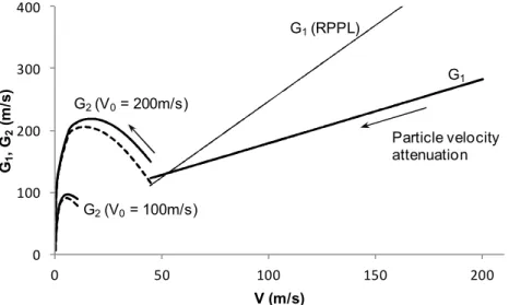
It can be shown that while the speed of propagation of the primary compaction wave, , depends only on the velocity during the first phase of deformation, while the speed of the secondary compaction wave, , depends on the history of the deformation process during Phase 1 (Figures 5c and 5d) as different levels of compaction are achieved at depending on the impact velocity. The speeds and of the primary and reflected waves, respective-ly are shown in Figure 7 for impact = 100 and 200 m/s. The Lagrangian wave speeds are shown by solid lines while the dashed lines represent the Eulerian speeds of the reflected compac-tion wave. One can see that the reflected wave, which propagates in a denser material, has a higher speed.
Figure 7: Speeds of propagation of primary,
G
1(
t
)
, and reflected,G
2(
t
)
, compaction waves; the thick lines represent the theoretical results according to Eqs. (6c) and (18c) andnumerical results; the thin line shows
G
1(
t
)
=V
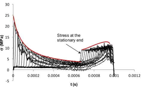
D due to the RPPL model.The present approach is also capable of predicting the maximum stress that occurs at each foam cross-section during deformation. A comparison between the theoretical prediction of the maxi-mum stress and the stress variation at a number of cross-sections due to the FE simulations is presented in Figure 8. It is evident that the theoretical model can capture well the magnitude and the propagation time of the primary and reflected wave in the foam.
)
(
1
t
G
)
(
t
V
)
(
2
t
G
1
t
t
)
(
1
t
G
G
2(
t
)
0
V
0 100 200 300 400
0 50 100 150 200
G1
,
G2
(m
/s
)
V (m/s)
G1
G1(RPPL)
G2(V0= 200m/s)
G2(V0= 100m/s)
Latin American Journal of Solids and Structures 12 (2015) 905-924
Figure 8: Maximum stresses along the foam rod within the primary and reflected compaction wave according to the theoretical model and the stress variation with time at a number of cross-sections predicted by the FE model;
the thick and thin lines represent the theoretical and numerical results, respectively.
4.2 Comparison Between the Present Theoretical Approach and a Model with a Predefined Densification Strain
The classical RPPL model (Reid and Peng, 1997) is frequently used to predict the velocity atten-uation and energy absorption of various cellular materials under impact loading. Therefore this model is used here to distinguish between the dynamic compaction of a foam material, which exhibits strain hardening and its approximation by the RPPL model.
The approximation of the actual material by the RPPL model removes the unique stress-strain dependence of the cellular material and the definition of the model parameters in terms of the critical, , (or plateau) stress and densification strain, , becomes crucial. Since the densifica-tion strain is not strictly a physical quantity, different definidensifica-tions for this parameter have been suggested. Obviously, a complete densification approaching the density of the constituent materi-al can be achieved mainly in very low density cellular materimateri-als subjected to a high velocity im-pact or other very high intensity loads. A physically rigorous approach to obtain was pro-posed by Tan et al. (2005a) providing more realistic estimates for the parameters of the RPPL model. The latter approach is used herein to obtain the characteristic parameters, = 0.405 and
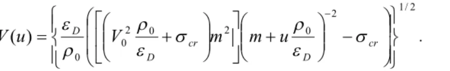
= 2.49 MPa for the Cymat material analyzed in the present paper and shown in Figure 1. The great advantage of the RPPL model is that a closed form solution for the velocity attenu-ation as obtained according to the expression given by Harrigan et al. (2010), which in the cur-rent notations reads
-5 0 5 10 15 20 25 30
0 0.0002 0.0004 0.0006 0.0008 0.001 0.0012
s
(M
P
a
)
t (s)
Stress at the stationary end
cr
DD
D
cr
Latin American Journal of Solids and Structures 12 (2015) 905-924 2 / 1 2 0 2 0 2 0 0
)
(
cr D cr D Du
m
m
V
u
V
. (24)
Assuming a constant predefined densification strain, the critical thickness of the foam, defined as
1
1
2 0 0
0 cr D
CR RPPL
V
m
L
(25)was also obtained by the same authors (Harrigan et al., 2010).
The velocities attenuations predicted by the RPPL model and currently proposed approach are shown in Figure 9 for initial impact velocities of 100 and 200 m/s. The predictions due to the numerical simulations (thin lines) are also added for comparison purposes. In both examples, the stroke (displacement of the rigid mass) is underestimated by the RPPL model thus overesti-mating the energy absorption capacity of the foam. Moreover, the predictions of the RPPL model for = 200 m/s are valid only for 0.0445 m as at this displacement of the impacting mass, the compaction wave reaches the stationary end. The latter model has no capability to deal with the reflected wave due to assumption of a locking strain.
Figure 9: Comparison between the velocity attenuation predicted by the current and RPPL material model for
V
0= 100 and 200 m/s.The assumption of the predefined strain is the major reason causing the disparity between the RPPL model predictions and actual deformation of a foam material when this model is applied to approximate foam with strain hardening (Karagiozova et al., 2012). This assumption leads to an incorrect estimate of the dynamic stress enhancement and in general overestimates this value. The comparisons between the dynamic stresses with the velocity attenuation presented in Figures
u
0
V
u
0 50 100 150 200
0 0.01 0.02 0.03 0.04 0.05 0.06 0.07
V ( m /s ) u (m) RPPL RPPL
Limit of the validity of the RPPL model
Latin American Journal of Solids and Structures 12 (2015) 905-924
10a and 10b for two impact velocities show that a considerable stress overestimation results from the application of the RPPL model.
The underestimation of the maximum stroke is also related to an incorrect evaluation of the minimum foam thickness, which is sufficient to absorb a given impact energy. According to Eq. (25), = 0.0578 m for = 100 m/s and 0.146 for = 200 m/s. In reality, the entire thickness of the 0.11 m foam block undergoes compaction at different strain levels (Figures 5b-5d) for both analyzed velocities whilst the initial impact energy cannot be absorbed by the propaga-tion of the primary compacpropaga-tion wave. A secondary compacpropaga-tion occurs and the stresses, which develop within this wave, are not negligible, particularly for the 200 m/s impact, as shown in Figure 10b.
In order to complete the comparison between the predictions of the RPPL model and the cur-rent approach, the compaction wave speed defined by the RPPL model, , is added in Figure 7. A considerable overestimation of the wave speed is observed, particularly for the higher particle velocities due to the constant value of .
It should be emphasized that a definite densification strain related to the material topology or density does not exist in metallic foam materials which exhibit considerable strain hardening (such as Cymat) as the plastic strains are velocity dependent. The compaction strains decrease rapidly with the propagated distance, which is particularly notable in the case of a small mass impact. The foam undergoes secondary compaction in order to absorb the initial kinetic energy. However, all models of foam compaction, which assume a locking mechanism, do not allow the analysis of the reflected wave. Therefore, despite the simplicity of the material models with pre-defined densification strains, they are not applicable to an impact by a small mass or/and to cel-lular materials with noticeable strain hardening.
CR RPPL
L
V
0V
0D
V
G
1
D
(10a)
0 2 4 6 8 10 12 14
0 20 40 60 80 100 120
s
d,
s1 d(M
P
a
)
V (m/s)
RPPL
Stress within the primary wave Stress jump
at the starionary end
s
ds
dLatin American Journal of Solids and Structures 12 (2015) 905-924
5 CONCLUSIONS
The unified approach for dynamic compaction of a class of cellular materials exhibiting strain hardening proposed in previous studies (Karagiozova et al., 2010, 2012, 2013, 2014) was extended in this paper in order to apply it to the foam compaction within the wave reflected from a sta-tionary boundary. The latter compaction is considered as a wave of strong discontinuity propa-gating in a media with non-uniform initial density, which increases monotonically in the direction of loading. The theoretical predictions are compared with FE simulation and good agreement is demonstrated. The proposed approach provides a reliable estimate of the energy absorption ca-pacity of a finite thickness foam block subjected to a uniaxial impact. This approach allows one to obtain the stress and strain variation within the reflected wave which has not been taken into account by the previously proposed models for compaction of cellular materials.
Acknowledgements
The financial support of the Brazilian Funding Agency, FAPESP, through Contract 2013/10884-3 is gratefully acknowledged
References
Barnes, A.T., Ravi-Chandar, K., Kyriakides S., Gaitanaros S., 2014. Dynamic crushing of aluminum foams: Part I – Experiments, Int. J. Solids Struct. 51, 1631-1645.
Davison, L., 2008. Fundamentals of Shock Wave Propagation in Solids, Springer-Verlag Berlin Heidelberg Gaitanaros, S., Kyriakides S., 2014. Dynamic crushing of aluminum foams: Part II – Analysis, Int. J. Solids Struct. 51, 1646-1661.
(10b)
0 10 20 30 40 50
0 50 100 150 200 250
s
d,
s1 d(M
P
a
)
V (m/s)
RPPL
Stress within the primary wave Stress within
the ref lected wave
s
ds
ds
1dLatin American Journal of Solids and Structures 12 (2015) 905-924
Harrigan, J.J., Reid, S.R., Tan, P.J., Reddy, T.Y., 2005. High rate crushing of wood along the grain. Int. J. Mech. Sci. 47, 521–544.
Harrigan, J.J., Reid, S.R., Yaghoubi, A. S., 2010. The correct analysis of shocks in a cellular material. Int. J. Impact Eng. 37, 918–927.
Hu, L.L., Yu, T.X., 2010. Dynamic crushing strength of hexagonal honeycombs, Int. J. Impact Eng. 37, 467–474 Karagiozova, D., Langdon, G.S., Nurick, G.N., 2010.Blast attenuation in Cymat foam core sacrificial clad-dings. Int. J. Mech. Sci. 52, 758–776.
Karagiozova, D., Langdon, G.S., Nurick, G.N., 2012. Propagation of compaction waves in metal foams exhibiting strain hardening, Int. J. Solids Struct. 49, p. 2763
Karagiozova, D., Alves, M., 2014. Compaction of a double-layered metal foam block impacting a rigid wall, Int. J. Solids Struct, 51, p. 2424–2438.
Karagiozova, D., Alves, M., 2014. Compaction of a double-layered metal foam block impacting a rigid wall, Ac-cepted in Int. J. Solids Struct
Langdon, G.S., Karagiozova, D., Theobald, M.D., Nurick, G.N., Lu, Merrett G., R., Mayimele N., 2010. Fracture of aluminium foam core sacrificial cladding subjected to air blast loading. Int. J. Impact Eng. 37, 638–651. Lopatnikov, S.L., Gama, B.A., Haque, M.J., Krauthauser, C., Gillespie, J.W. Jr., 2004. High-velocity plate impact of metal foams. Int. J. Impact Eng. 30, 421–445.
Main, J.A. and Gazonas, G.A., 2008. Uniaxial crushing of sandwich plates under air blast: influence of mass dis-tribution,Int. J. Solids Struct., 45, 2297–2321
Nowacki, W.K., 1978. Stress-Waves in Non-Elastic Solids, Pergamon Press, UK.
Pattofatto, S., Elnasri, I., Zhao, H., Tsitsiris, H., Hild, F., Girard, Y., 2007. Shock enhancement of cellular struc-tures under impact loading: Part II analysis. J. Mech. Phys. Solids, 55, 2672–2686.
Reid, S.R., Peng, C., 1997. Dynamic uniaxial crushing of wood.Int. J. Impact Eng. 19, 531–570.
Tan, P.J., Reid, S.R., Harrigan, J.J., Zou, Z., Li, S., 2005a. Dynamic compressive strength properties of alumini-um foams. Part II – ‘shock’ theory and comparison with experimental data and nalumini-umerical models. J. Mech. Phys. Solids, 53, 2206–2230.
Tan, P.J., Reid, S.R., Harrigan, J.J., Zou, Z., Li, S., 2005b. Dynamic compressive strength properties of alumini-um foams. Part I – experimental data and observations. J. Mech. Phys. Solids. 53, 2174–2205.
Tan, P.J., Reid, S.R., Harrigan, J.J., 2012. On the dynamic mechanical properties of open-cell metal foams – A re-assessment of the ‘simple-shock theory, Int. J. Solids Struct. 49, 2744–2753
Zhang, J. et al. Dynamic crushing of uniform and density graded cellular structures based on the circle arc model. Accepted in Latin American Journal of Solids and Structures.
Zheng, Z., Liu, Y., Yu, J., Reid, S.R., 2012. Dynamic crushing of cellular materials: Continuum-based wave mod-els for the transitional and shock modes, Int. J. Impact Eng. 42, 66-79