Abstract — In this paper, an analytic comparison between adaptive
modulation (AdM) and adaptive Forward Error Correction
(AdFEC) in wireless network telecommunication systems is
performed. Through the Gilbert-Elliott model's, the Packet Error
Rate (PER) is calculated and both the throughput and the delay,
for different modulations and error correction capacity, have been
also computed. For the throughput criterion, the results show that
the AdFEC outperforms AdM for higher values of Signal
Noise-to-Ratio (SNR). However, when the SNR has low value the adaptive
modulation performs better. In case of delay criterion, the mean
time to transmit a packet using AdM is lower than when AdFEC is
used.
Index Terms — Adaptive modulation, Adaptive FEC, Packet Error Rate, Performance.
I. INTRODUCTION
The rapid growth in the use of information networks, increasing the data rates, led to the necessity to
implement novel technique aiming to improve wireless networks communication performance. In
conventional communication systems, transmission characteristics are adjusted for the worst channel
setting behavior in order to provide a lower limit to a specific error rate [1]. Adaptive Modulation and
Coding (AMC), which includes both adaptive modulation (AdM) and adaptive Forward Error
Correction (AdFEC) operating together, have been developed to face fading and enhance the wireless
systems performance. They maximize bandwidth efficiency through selecting an optimal combination
from the modulation and coding scheme (MCS), where the resolution depends on the channel state
information. Consequently, every modulation and code scheme will be linked to a constellation size
and coding rate respectively [2]. AMC allows spectrally efficient transmission in function of
time-ANALYTICAL COMPARISON OF THE
PERFORMANCE OF ADAPTIVE
MODULATION AND CODING IN WIRELESS
NETWORK UNDER RAYLEIGH FADING
Sabi Y.M. BANDIRI , Rafael M.S. BRAGA and Danilo H. SPADOTI
Federal University of Itajubá
varying channels. The AMC technique is designed to track channel variations and then change the
modulation and/or coding scheme. The goal is to yield a higher throughput by transmitting with high
information rates under favorable channel conditions and by reducing the information rate in response
of channel degradation [2]- [5]. In case of high fading, for example, the size of the signal constellation
is reduced to improve the fidelity. Thus, a more robust transmission for effective SNR is required.
Conversely, for low fade or high gain period, the size of the signal constellation is increased to reach
high throughput [6].
In AdM, the number of transmitted bits per symbol varies as a function of the channel’s
characteristics [6]. The basic idea is as following: if the bit error rate (BER) in the channel exceeds a
given threshold, the number of transmitted bits per symbol is reduced (reducing the transmission rate
in the channel), while keeping the transmitted average symbol energy at a constant level [6-11]. This
improves the BER and, consequently, the packet error rate (PER). Therefore, the modulation scheme
depends on the instantaneous BER (or SNR) in the wireless link.
For Ad-FEC schemes case, the redundancy of the code used to control error in the wireless link
varies according to its performance. The main idea is the following: if the BER in the channel exceeds
a given threshold, the number of bit parity is increased [11]. As a consequence, the error correction
capacity of the code is improved (reducing the probability of a packet to contain an uncorrectable
error) and the throughput is reduced. Adaptive Automatic Repeat reQuest (ARQ) scheme has the
same principle, nevertheless, here the aim is to reduce the probability of a packet to contain
undetectable error [12].
Several papers have approached AMC techniques in wireless networks under fading channels
without considering the relationship between adaptive modulation and adaptive code [6-8]. The
authors in [8] combine trellis coding with adaptive modulation to increase the spectral efficiency of
adaptive modulation over fading channels. Their results show that a 3dB coding gain relative to
uncoded adaptive modulation for a simple 4-state trellis code, and a 4dB coding gain for an 8-state
trellis code. Despite of these results, the authors did not carry out the performance of adaptive
modulation and code. In [12], the authors have deployed a combined modulation and FEC adaptive
scheme to wireless multi-access Asynchronous Transfer Mode (ATM) networks. Nonetheless, he has
considered additive white Gaussian noise (AWGN) channel, which does not accurately describe the
real condition of the channel. In references [13] and [14], respectively, the performance of adaptive
modulation and adaptive FEC in wireless network under fading channel were separately investigated.
But, the comparative analysis of the performance of both techniques were not been realized.
Therefore, the main objective of this work is to compare, adaptive techniques performance
when they operate together in the same condition. Throughput and delay criteria are used for analysis
in the wireless network under Rayleigh fading. Thus, a more realistic situation of the wireless network
The remainder of this paper is organized as follows: in Section 2, the packet error rate under
Rayleigh fading channel using Gilbert-Elliot models is evaluated. In Section 3, we have compared the
performance of both AMC techniques (AdM and AdFEC) by using throughput criteria. In Section 4,
we have calculated and compared the mean time to forward a correct packet using both techniques.
Finally, the conclusions are presented in Section 5.
II. MODEL TO COMPUTE THE PACKET ERROR RATE
In a wireless communication system with a Rayleigh fading channel, errors tend to occur in bursts
instead of random errors that occur in an Additive White Gaussian Noise (AWGN) channel [15]- [17].
Several studies and proposals have introduced empirical or approximate methods for PER computing
in a channel with memory [15]- [17]. They concluded that such calculation is quite complex, imprecise
and cannot be generalized to the real applications. To calculate or estimate the PER, all proposed
methods above model the communication channels according to a Markov chain, where the SNR ratio
is partitioned into a finite number of states, that can range between two and several. The difficulties of
working with Markovian models are in to set the transition probabilities of states to reflect the real
channel behavior. In another way, the Gilbert-Elliott (GE) is one of the simplest model, which provides
a useful discrete model, being that the parameters can be readily related to the statistics of the fade
[18]- [20]. The GE channel assumes that the channel can be represented by a discrete time Markov
chain with two states: Good state (G) and Bad state (B). Fig. 1 illustrates a GE with transition
probabilities (The channel conditions move from bad state to good state) and (the channel
conditions move from good state to bad state). As shown in Fig.1, each state is modeled as a Binary
Symmetric Channel (BSC) with bit error probabilities pg, in G state, and pb in B state.
G B
1
1
0 0
1 1
1-pg
1-pg pg pg
0 0
1 1
1-pb
1-pb pb pb
Fig.1. Gilbert-Elliott Channel [16].
Considering that the channel fades slowly under Rayleigh fading and with respect to a bit interval,
the probability density function of the SNR is given by [21]:
1 0
e
f (1)
A given threshold, ψ, has been chosen to define the status of the channel. The model considers that
the channel is said to be in the good state when the SNR is above that threshold, ψ, and once the SNR
drops below the threshold, ψ, the channel goes to a bad state. The transition probabilities in the GE
channel can be calculated using the level crossing rate and the SNR density function as in [18]:
1 2 e T
fd
(2)
fdT 2 (3)where, T is the symbol interval and, fd, is the maximum Doppler speed. The parameter, , is the ratio
between the threshold, , and the average SNR in the wireless channel. As in [18], the was set to
0.1, thus, a 10 dB SNR below the average SNR represents the transition to the bad state and the
product, T fd , is equal to 0.01. According to the results obtained in [18] and [19] these values
outperform other values proposed in their literature.
The steady state probabilities of the Markov chain illustrated in Fig.1 are given by [18]:
g (4)
b (5)
where g (this is the probability of the channel condition stay in good state) and b (this is the
probability of the channel condition stay in good bad) are the steady state probabilities of GE channel
being in the good and bad states, respectively.
In GE channel, The BER (pg, pb) associate to each state of the Rayleigh fading for a given
modulation scheme is computed as following [18]:
d f d f BERpg (6)
0 0 d f d f BERin which BER() is the bit error rate for an AWGN channel with SNR equal to, and f() is the
probability density function of Rayleigh fading presented in (1). The bit error rate for an AWGN
channel, with the considered modulation, can be determinate using classical equations [21].
With the bit error rates calculated using (6) and (7), the packet error rate in each state of the channel
can be computed. A system without FEC is considered for adaptive modulation technique. Thus, the
packet error rate in each state is the probability of packet error in a BSC, considering the proper BER
for each state. These probabilities are given by [18]:
ng
g p
p
P 11 (8)
nb
b p
p
P 1 1 (9)
where, n is the length of each packet in bits transmitted in each slot, and pgand pb are given by (6) and
(7), respectively.
However, if FEC is considered, the probabilities of packet error in a BSC can also be easily
computed by simply considering the error correction capacity of the FEC code. The probabilities of
packet error in each state are given by [18]:
0
1 (1 )
t
n i i
g g g
i
n
P p p p
i
(10)
0
1 (1 )
t
n i i
b b b
i
n
P p p p
i
(11)Finally, the packet error rate in the Rayleigh channel is determinate by [16]:
PERgP p
g bP p
b (12)where, G and B are given by (4) and (5), respectively, and P(pg) and P(pB) are given by (8) and (9)
for AdM and by (10) and (11) for AdFEC, respectively,
In this proposal, the Time Division Multiple Access (TDMA) was considered, where the
modulation can be defined on a frame by frame basis [12].
The modulation schemes considered in this paper are: BPSK (Binary Phase Shift Keying), QPSK
(Quaternary PSK), 8-PSK and M-QAM (M – Quadrature Amplitude Modulation) with M = 16, 32, 64,
128 and 256 respectively. In the QAM systems, square constellations for M = 16, 64 and 256 and
rectangular constellations for M = 32 and 128 have been considered. The expression to compute the bit
error rate in each considered modulation as a function of Es/No can be obtained in [21].
There are several codes to correct bursts errors in wireless networking [22]- [25]. Nonetheless, the
to form a large class of powerful random error-correcting cyclic codes to implement FEC scheme.
Therefore, this code is considered in the AdFEC system. For any positive integers m (
m
3
) and t(t2m1), there exists a binary t-error correcting BCH code with the following parameters [22]:
1
2m
n block length
n k mt, number of parity check digits
2 1 min
d t , minimum distance
To have an exact parameter for comparison as in [12], the number of bit information has been set
to k=424 for PER computing.
Fig. 2 indicates the PER in function of Es/No. From this figure, the PER decreases with the
increase of the Es/No, which means that the channel tends to stay more in the good state than to the
bad state. For a given Es/No ratio, the modulation with highest number of points in the constellation
scheme has the highest packet error rate (PER). If the Es/No ratio is set constant and when channel
conditions are unfavorable, it would be appropriate to use modulation with fewer points in the
constellation scheme (reducing the transmission rate) in order to maintain high system performance
on the wireless link.
16 18. 2 20. 4 22. 6 24. 8 27 29. 2 31. 4 33. 6 35. 8 38 0.15
0.32 0.49 0.66 0.83 1
256QAM 128QAM 64QAM 32QAM 16QAM
Es/No
P
ac
ke
t E
rr
or
R
at
e
P
E
R
Fig.2 – Packet Error Rate vs Es/No
III. CRITERIAOFTHROUGHPUT
One of the criteria used to compare the performance for both systems is based on throughput in the
wireless channel. This approach has been considered in the scenario where the traffic is real-time and
number of correct packets transmitted per second in the wireless network under Rayleigh fading
channel. Thus, the throughput is computed as following [11]:
2
2 log
1 log
i n
r i
M k
V PER
M n
(13)
where
M
iis the number of points in the constellation of the current modulation,M
ris the number ofpoints in the constellation of the reference modulation, k is the number of information bits in each
packet transmitted in the wireless link,
n
i is the total number of bit in each packet in the wireless link(k plus the number of parity bits, not considering protocol headers).
PER
is the packet error ratedefined in (12).
For the adaptive modulation scheme, error control code is not used (
n
i=k), and the maximumthroughput is given by :
2
mod2
log 1 log
i
r M
Th PER
M
(14)
When the system switches from determinate modulation to another, the average symbol energy
Es/No (or transmission power) is kept constant. The parameter Eb/No (average bit energy to noise
density) changes at the switch time. Therefore, the performance evaluation of the modulation schemes
is performed as a function of the parameter Es/No (average symbol energy to noise density ratio) [23].
For adaptive FEC scheme, fixed modulation is used as reference in the maximum throughput
definition (
M
i
M
r), and it can be written as:
1
fec i k
Th PER
n
(15)
To compare the performance between AdM and AdFEC, the maximum throughput of both
techniques is computed according to (14) and (15). The results are shown in Fig.3 and in Fig.4 where
256-QAM modulation and 64-QAM modulation are used as reference, respectively. In Fig.3 the
switching point between both curves is Es/No=22.88 dB with PER=0.031. However, for Fig.4 the
switching point among AdM and AdFEC curves is Es/No=17.56 dB with PER=0.029. Therefore, the
switching points among AdM and AdFEC depend on the reference modulation used.
An analytic comparison of the performance in Fig.3 and Fig.4 indicates that, for lower value of
Es/No (when Es/No is less than 22.88 dB for 256-QAM and less than 17.56 dB for 64-QAM) adaptive
modulation outperforms AdFEC. The possible reason is that: the SNR is the relationship between
values mean high noise in the channel. Thus, AdM case requires using modulation with low points on
its constellation format (to ensure less PER), such as: BPSK, QPSK. Consequently, the throughput
increases, since PER decreases. In contrast, for the AdFEC technique, the number of bit parity is
increased to guarantee the error correction, and the code error correction capacity is improved.
However, increases the bit parity, highly decreases the throughput (see Eq.15), which leads the
AdFEC throughput to be lower than the AdM.
On the other hand, for high values of Es/No, the AdFEC outperforms AdM. The throughput of the
AdFEC technique is better for high SNR (low noise) values, because there is no necessity to
increment the parity bits in such case, instead, it is reduced since the errors are low. However, for high
values of Es/No, AdM considers modulations with large constellation schemes (e.g.: 128QAM,
256QAM) that provides a better transmission rate, nonetheless more susceptible to errors. This leads
the throughput of the AdFEC technique better than AdM. Thus, AdFEC is more indicated when the
channel conditions are in bad state. AdM can be used when the channel conditions are in good state
since at this canal condition the PER is lower. Similar conclusion has been done in [12], nevertheless,
in their case, the channel considered was memoryless and this type of channel does not describe the
real situation of wireless network communications behavior. Therefore, as conclusion, AdFEC will
present better performance independently of channel model, but the crossing point will change
according to the channel and the reference modulation.
18 20 22 24 26 28 30 32 34 36 38
0 0.1 0.2 0.3 0.4 0.5 0.6 0.7 0.8 0.9 1
Adaptive Modulation Adaptive FEC
Es/No (dB)
T
hr
oug
hpu
t
Fig.3. Throughput as a function of Es/No for the adaptive FEC and adaptive modulation schemes (the 256-QAM is the
13. 6 17. 48 21. 36 25. 24 29. 12 33 0.1
0.2 0.3 0.4 0.5 0.6 0.7 0.8 0.9 1
Adaptive modulation Adaptive FEC
Es/No (dB)
T
hr
oughput
Fig.4. Throughput as a function of Es/No for the adaptive FEC and adaptive modulation schemes (the 64-QAM is the
reference modulation).
Table 1 summarizes the results obtained from Fig.3 and 4 and, for easily comparison, the
results from Fig.4.6, Fig.4.7 from [12] were also added.
From Table 1 we appreciate the followings cases:
The switching occurs in high values of Es/No in [12], when we compare with this
work.
The value of the PER is greater in [12] than in this paper.
Throughput value of this proposal is lower than the presented in [12].
All the above results can be explained by the fact that, in this work, a more realistic situation was
considered, once the channel is not perfect but subject to adverse conditions. High packet loss
generates a high PER and as consequently the throughput of the wireless communication network is
reduced.
TABLEI.COMPARISON OF SWITCHING POINTS, PER AND THROUGHPUT OF THIS PAPER AND [12].
Es/No (dB) PER Throughput
AMC +256QAM 22.88 0.031 0.345
AMC + 64QAM 17.46 0.029 0.273
Ref [12] + 256QAM 25 0.013 0.733
IV. DELAY CRITERIA
In non-real data transmission system, typically errors in the wireless link are corrected by
retransmission using Automatic Repeat reQuest (ARQ). One errored bit is enough to result in
retransmission of the entire packet. The receptor can request a retransmission of the entire packet until
success transmission of all the bits of the packets. In this system, the average time to transmit a
correct packet is a proper quality-of-service (QoS) parameter to evaluate the performance. The
interval of time between the conclusion of reception of an errored packet and the beginning of its
retransmission, have not being considered.
To compute the delay, we considered a TDMA system with, X, time slots in a frame, with ns
bits being transmitted in each slot. Each packet was transmitted over, Z, slots (one packet needs Z
time slots to be transmitted), and it was retransmitted until be correctly received (we consider that
number of retransmissions was unlimited). A slow fading channel (the duration of fades was much
greater than the duration of packet transmission) was also considered.
For AdFEC, the mean time to transmit a correct packet over Z slots Tfec, considering conditions
above, where the duration of fades is much greater than the duration of packet transmission time, can
be computed by [14]:
21 1
1 log
s fec
n Z X T
PER B M
(16)
where, B is the bandwidth, and M the symbol number according to the modulation considered. The
FEC codes are applied in each time slot, thus, (10) and (11) should be modified in order to calculate
correctly the new packet error probabilities associated with each state good and bad. Therefore, the
PER is the packet error rates computed by (12) with n = Zns.
In the context of AdM system, the mean time to transmit a packet, for a given modulation,
whereas retransmissions are done at packet level (i.e., the retransmission request is made to the
complete packet and not the fragments transmitted in each time slot) may be calculated by the
following equation [13]:
21 1
1 log
s mod
n Z X
T
PER B M
(17)
As the retransmission is made at packet level, (8) and (9) have to be modified also according to the
channel state. The new PER associated to each state is calculated with n = Zns in (8) and (9). For this
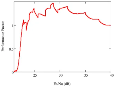
With the purpose to compare the performance of both techniques (AdM and AdFEC) using the
delay criteria, a performance factor has been defined as the relationship between the mean time to
transmit a packet without error in the system with AdM and the mean time to transmit the same
packet by using AdFEC. The results presented in Fig.5 show that the average time to transmit a
packet using the AdFEC technique is larger than the average time to transmit a packet by using AdM
technique for Es/No ≥ 28.13 dB. This could be explained by the fact that in the AdFEC technique the
spent average time to send a packet includes both the transmission time and the spent mean time at the
receiver to correct any errors during the transmission of the packet. This spent mean time at the
receiver is not considered in the AdM technique. In [12], the AdFEC has better or equal performance
to the AdM for Es/No ≥ 23.6 dB. The value of the performance factor where adaptive FEC performs
better or equal to adaptive modulation is 1.009 in [12], and this value was got 1.209. This high value
of the performance factor in our proposal can be explained by the high value of PER, since the
channel conditions are subject to Rayleigh fading.
Hence, a hybrid technique that results from the combination of these two techniques can
improve system performance.
25 30 35 40
0 0.5 1
Es/No (dB)
P
e
rfo
rm
anc
e
F
a
c
tor
Fig. 5. Performance factor between adaptive modulation and adaptive FEC.
V. CONCLUSION
In this paper, the performance of AdFEC and AdM has been compared in wireless network
communication under Rayleigh fading. AMC techniques performs in different range of SNR. AdFEC
performs better than AdM in most SNR range. However, for a lower value of SNR adaptive
modulation has better performance when a throughput criterion is used. Also, the mean time to
transmit a packet using AdFEC is higher than the time used to transmit the same packet for AdM.
will be appropriated rather than adaptive FEC. Further, a hybrid technique (where both techniques are
combined) will be a good candidate to improve better the performance of the wireless network.
ACKNOWLEDGMENT
THE AUTHORS WOULD LIKE TO THANK CAPES,CNPQ AND FAPEMIG.
REFERENCES
[1] H. I. Anwar, I. Ibrahim, K.W. Hon and Y. A. Razak, “Performance and Simulation of Adaptive Modulation Techniques of the WIMAX Network via AWGN Channel”, Australian Journal of Basic and Applied Sciences, 8(4) Special 2014, pp. 291-293.
[2] J. Yang, A. K. Khandani and N. Tin, “Adaptive Modulation and Coding in 3G Wireless Systems”, Proceedings on 56th Vehicular Technology Conference, VTC 2002-Fall, pp. 544-548.
[3] J. Faezah and K. Sabira, “Adaptive Modulation for OFDM Systems”, International Journal of Communication Networks and Information Security (IJCNIS), Vol. 1, No. 2, August 2009, pp.1-8. [4] K. Shatarasi and S. R. Reddi, “Throughput and Error State Performance of AMC Scheme in 3G Wireless Systems”, IOSR Journal of Computer Engineering, Vol. 9, Issue 6, Mar-Apr. 2013, pp. 89-92.
[5] A. Zalonis, N. Miliou, I. Dagres, A. Polydoros and H. Bogucka, “Trends in adaptive modulation and coding”, Advances in Electronics and Telecommunications, Vol. 1, No 1, April 2010, pp. 104-111.
[6] J. Tang and J. Wang, “Adaptive modulation for fading channels”, IEEE Asia-Pacific Conference on Circuits and Systems – APCCAS, 2000, pp. 58-61.
[7] I. Forkel, A. Kramling and D. Bernhardt, “On allocation and adaptive transmission technology in fixed wireless access networks”, 4th European Personal Mobile Communications Conference, Vienna, Austria, 2001.
[8] A. J. Goldsmith and S. G. Chua, “Adaptive coded modulation for fading channels”, IEEE Transactions on Communications, 46(5), 1998, pp. 595-602.
[9] J. M. Torrance and L. Hanzo, “Latency considerations for adaptive modulation in an interference-free slow Rayleigh fading channel”, IEEE Vehicular Technology Conference, Vol. 2, 1997, pp. 1204-1208.
[10] J. M. Torrance and L. Hanzo, “Optimisation of switching levels for adaptive modulation in slow Rayleigh fading”, Electronic Letters, Vol. 32, No 13, June, 1996, pp. 1167-1169.
[11] J. M. C. Brito and I. S. Bonatti, “Analysing the optimal threshold level for adaptive modulation in the wireless ATM networks”, Proc. of the Iasted International Conference on Wireless and Optical
Communications, Banf, Canada, July 2002, pp. 510-515.
[12] J. M. C. Brito and I.V. Bonatti,
“A
combined modulation and FEC adaptive scheme to wireless multiaccess ATM networks”International Telecommunications Symposium, Natal/RN-Brazil, Sept: 2002, pp.157-162[13] S.Y.M. BANDIRI and J.M.C. Brito, “Analyzing the optimum switching points for adaptive modulation in wireless networks with rayleigh fading” IEEE Latincom, in the 6th Latin-American Conference on
Communications, Nov.5th to 7th 2014 in Cartagena de Indias, Colombia
[15] H. Bischl and E. Lutz, “Packet Error Rate in the non-interleaved Rayleigh channel”, IEEE Transactions on Communications, Vol. 43, No 2/3/4, February/March/April 1995, pp. 1375-1382.
[16] R. Khalili and K. Salamatian, “A new analytic approach to evaluation of packet error rate in wireless networks”, Proceeding of the 3rd Communication Networks and Services Research Conference, 2005, pp. 333– 338
[17] Y. Xi, A. Burr , J. Wei and D. Grace, “A general upper bound to evaluate packet error rate over quasi-static fading channels”, IEEE Transactions on Wireless Communications, V.10, No 5, May 2011, pp. 1373 -1375.
[18] C. Jiao, L. Schwiebert and B. Xu; “On modeling the packet error statistics in bursty channels”, Proceedings on 27th Local Computer Networks - LCN, November 2002, pp. 534-541.
[19] G. Sharma, A. Dholakia and A. Hassan, “Simulation of error trapping decoders on a fading channel”, Proc. IEEE Vehicular Technology Conference, Atlanta, USA, May 1996, pp. 1361-1365.
[20] A. Seddiki, A. Djebbari, J.M. Rouvaen, A. Taleb-Ahmed, “Performance evaluation of BCH correcting codes on a fading channel using OFDM modulation”, Proceedings of the 11th WSEAS International Conference on Communications, Crete Island, Greece, July 2007, pp. 340-346.
[21] E. O. Elliot, “Estimates of error rates for codes on burst-noise channels, Bell Syst. Tech. J., Vol 42, September 1963, pp. 1977-1997.
[22] B. Sklar, Digital Communications: Fundamentals and Applications – second edition. Prentice Hall, 2001.
[23] A. Seddiki et Al, "BCH Coding Performance Evaluation on a Land Mobile Channel Based OFDM System", Information Technology Journal 5, 2006, pp: 930-936.
[24] J. Gomes and B.K. Mishra, “Double Error Correcting Long Code", International Journal of Computer Networks & Communications, Vol.2, No.5, September 2010, pp: 58-69.

![TABLE I . C OMPARISON OF SWITCHING POINTS , PER AND THROUGHPUT OF THIS PAPER AND [12].](https://thumb-eu.123doks.com/thumbv2/123dok_br/18888296.424365/9.893.101.787.869.1029/table-i-c-omparison-switching-points-throughput-paper.webp)