Reginaldo T. Coelho
[email protected] University of São Paulo School of Engineering at São Carlos Department of Production Engineering 13566-590 São Carlos, SP, Brazil
Hugo H. T. Rodella
[email protected] University of São Paulo School of Engineering at São Carlos Department of Production Engineering 13566-590 São Carlos, SP, Brazil
Vinícius F. Martins
[email protected] University of São Paulo School of Engineering at São Carlos Department of Production Engineering 13566-590 São Carlos, SP, Brazil
Rossana Barba J.
[email protected] University of São Paulo School of Engineering at São Carlos Department of Production Engineering 13566-590 São Carlos, SP, Brazil
An Investigation into the Use of
Industrial Robots for Machining Soft
and Low Density Materials with HSM
Technique
The needs to comply with an increasingly competitive international market lead industries to some innovative solutions, such as the use of robotic arms as machine tools. Although these solutions present some well known drawbacks, there are some advantages and niches of application where success is possible. The present work investigates the use of such pieces of equipment to machine aluminum alloys AA2024 applying high speed machining (HSM) technique, assessing surface finishing as a function of different orientation angles between end mill and machined surface. It also tests the best condition to machine foam for prototyping applications. Results indicate that the directions close to the normal are the best compromises because of dynamic stability of the robot arm structure and roughness as low as 4 µm Ra are possible to be achieved in aluminum alloys. A complex shape such as a semi sphere can be easily machined in foam for rapid and accurate prototype machining. Surface finishing can be very smooth and well suitable for industrial applications in such materials.
Keywords: robot, HSM, rapid prototyping, machining
Introductiona
In attempts to comply with the increasing demands for high performance in machining operations, new solutions arise in the market every day. One of those is the use of robotic arms as machine tools. Although many limitations have been pointed out in the past, some advantages can also be visualized, such as, mechanical re-configurability, ability to work with different tooling and simple fixtures, re-programmability through the control computer, which can make them ideal for particular niches of applications (Sabri and Ray-long, 1990). In aerospace and precision die making industries, for example, there is great need for machining complex shapes, which require 5-axis machines in finishing milling operations and even grinding, or polishing (Ning et al., 2005). But those are not the most suitable uses for industrial robots, since they present low stiffness and low precision in positioning, unless such problems can be solved, which does not seems to be the case in a short period of time. Therefore, they are not capable of competing with conventional or special parallel kinematic machine tools (Fei et al., 2009). On the contrary, in applications where flexibility, complex surfaces, rapid prototype machining operations and, especially, stiffness are not an important requirement, industrial robots may be the ideal machine tool. Among such applications, some can be listed: rapid prototyping, burr removal, and even drilling, provide that all materials being machined are low strength and easy to cut ones (Schaaf, 2000). Among those are some aluminum alloys, magnesium alloys, wood, plastics and also some composites with plastic/resin matrices and low strength reinforcements (Cezary et al., 2003; Huang, et al., 2002).
Paper received 13 September 2010. Paper accepted 12 May 2011.
Machine tools with more than 4 axis are, usually, very expensive (easily above €500K) and their maintenance has to be strongly justified in industries for periods as long as 10 years. In contrast, a 6 axes robot, with a 10 kg payload, can be less expensive (around €50K), easier to deal with in a normal industrial environment and it can also perform a variety of machining operations using different tooling systems (Antunes et al., 2003). Additionally, the drawbacks often pointed out can, to some extent, be overcome by the use of appropriated solutions.
Positioning error, for example, when using robots are often regarded as excessive compared to normal machining tools. However, the use of force as a feedback signal to compensate the trajectory error has been studied and may be the solution in some applications (Sabri and Ray-long, 1990). For some other applications a combination of acoustic emission (AE) and electrical power may be more suitable for adjustments on the trajectory and error corrections (Oliveira et al., 2004). By a pre-compensation concept for continuous path in robotic, using a path regulation, it was possible to machine with reasonable precision, according to simulations described by Chin and Tsai (1993). All those proposed solutions have been tested in academic environment, so far.
The stiffness of industrial robots has also been extensively studied, modeled and lately, improved. Some publications and researches identify the gears as main responsible for the system compliance. Depending on the type and size of a robot, gears range from 50% to 75% of the overall compliance (Abele et al., 2007). Although the stiffness can be a problem, if the HSC (High Speed Cutting) technique is applied on machining with industrial robots, the problem can be minimized. The idea of applying high cutting speed combined with low feed per tooth and depth of cut may keep material removal rate at acceptable levels and significantly minimizes the forces acting on the robot structure. However, additional problems can arise regarding vibrations, reaching a point where chatter may occur. That can lead into different problems addressed as a regenerative chatter (Altintas, 2000) or mode coupling chatter, which may explain the low frequency vibration in certain machining setups using robots (Zengxi et al., 2006).
When milling complex surfaces using ball nose end mills, the tool contact point with the machined surfaces vary over the entire nose radius. Basically, the tool axis can have one angle measured from the feed direction, another in the perpendicular orientation. When those angles vary the tool contact point with the machined surface changes and, as a consequence, the cutting edge geometry and the cutting speed are different. As the contact point moves closer to the tool center, the rake angle becomes more negative and cutting speed lower. Thus, chip formation tends to worsen, but stiffness can be improved. At the center, when both angles are 90 degrees, the cut again tends to be very unstable and lateral stiffness the worst. Works developed by Batista (2006) and Capla (2006) are two examples addressing the problems found with slippage and tool stiffness at normal direction, respectively. Therefore, there might be an optimum position regards chip formation and stiffness, which must be investigated.
The present work investigates some applications for an industrial robot machining aluminum alloy and also low density and easy to machine material for prototyping. A special and light weight machining head was built using a commercial and low cost electric motor. Ball noses end milling cutters with 2 and 4 flutes were used with HSM technique to perform milling operations on a flat surface, simulating tool contact in complex shapes. Experimental vibration analyses were performed and surface finishing was assessed as a function of several angles between the end mill and the flat machined surface.
Nomenclature
AE = Acoustic Emission
ae = width of cut in the X direction, mm
ap = depth of cut in the Z direction, mm
CL = Cutter Location
FRF = Frequency Response Function fz = feed per tooth, mm/rev HSC = High Speed Cutting HSM = High Speed Machining PR = Position Repeatability vc = cutting velocity, m/min
vf = feed velocity, mm/min
X,Y,Z = coordinate system Greek Symbols
α = tool reference angle in the Y direction, degrees β = tool reference angle in the X and Z directions, degrees Superscripts
2 = 2 flutes 4
= 4 flutes
Experimental Work
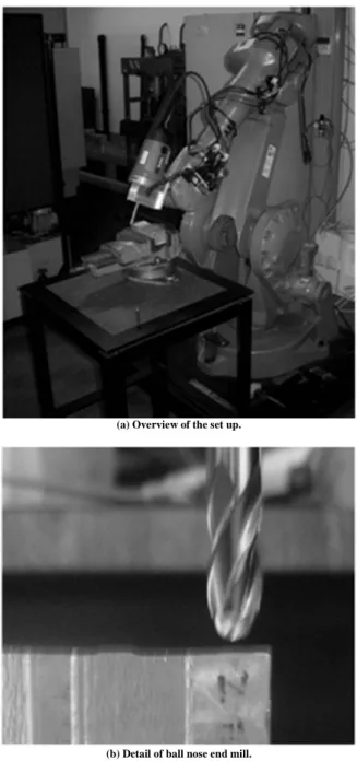
The experimental work was developed in a ABB 6 axes robot model IRB240, with payload equal to 10 kg, whose performance, according to ISO 9283, is Position Repeatability (PR) 0.03–0.07 mm, path repeatability 0.11–0.15 mm (both depending on variant) and maximum reach 1.55 m. The experiments used HSS ball nose end milling cutters, 10 mm diameter with 2 and 4 flutes. To perform the tests, the robot was equipped with a specially designed milling head, which was built with aluminum case, high speed ball bearings and the end mills fixed by shrink thermal fitting. An ar cooling system was also incorporated to the milling head, helping to keep the performance of the bearing at high speeds. Figure 1 shows an overview of the arrangement.
(a) Overview of the set up.
(b) Detail of ball nose end mill.
Two materials were milled, AA2024 aluminum alloy and a foam material used in foundry and for prototyping applications. The first experiment tested the capacity to machine light soft alloys, assessing the surface finishing limitations and the second one, the capacity to machine complex surfaces on very soft materials. In both cases it was used ball nose tools, which are capable of machining with different angles between its axis and the machined surface. Two angles were defined in the present work: α and β. Taking the feed direction as reference (Y axis in Fig. 2), β was measured upward from that on a plan formed with the normal direction (Z axis in Fig. 2). Additionally, that plan can also be different from perpendicular (in relation to the machined surface) and in such case the inclination angle was called α (Fig. 2). The angles α and β were set by the robot control system, after it had been calibrated, and checked with a mechanical angle meter. The best positioning angle, found in the first trials, was used to perform the second experiment on the foam material.
Machining conditions were according to recommendations from tool manufacturer, as shown in Table 1. For both tools the reference angles, according to Fig. 2, were varied in a range allowed by the robot arm and in searching for better surface roughness.
Surface roughness was assessed by a Form Talysurf™ and 5 measurements were averaged for each cutting condition tested using 2.5 mm cut off. Surface profiles were also plotted covering 8 mm on X direction (perpendicular to feed direction) and 30 mm on the Y direction (feed direction, in Fig. 2).
Figure 2. Reference angles (α and β) used to evaluate their influence on the surface roughness.
Table 1. Codes and reference angles of all the experimental cutting tests performed.
Code 90_45 90_60 90_90 90_120 90_135 45_90 60_90
Rpm 26,000 26,000 26,000 26,000 26,000 26,000 26,000
Largest cut
diameter (mm) 4.72 4.14 4.35 4.14 4.72 4.72 4.14
vc (m/min) 385 338 355 338 385 385 338
vf (mm/min) 3000 3000 3000 3000 3000 3000 3000
fz (mm/rev)
0.0572 0.0284 0.0572 0.0284 0.0572 0.0284 0.0572 0.0284 0.0572 0.0284 0.0572 0.0284 0.0572 0.0284
ap (mm) 0.5 0.5 0.5 0.5 0.5 0.5 0.5
ae (mm) 0.2 0.2 0.2 0.2 0.2 0.2 0.2
α 90° 90° 90° 90° 90° 45° 60°
β 45º 60º 90º 120º 135º 90º 90º
To assess the dynamic behavior of the whole machining system, “tap-tests” were conducted using a piezoelectric hammer, PCB Code 086C03, with sensitivity of 2.25 mV/N and an accelerometer PCB Code 320C04 with sensitivity of 10mV/g connected to an acquisition module from National Instruments code NI9233. To extract the FRF, dynamic stiffness and natural frequencies the CutPro™ software was used. The test was performed in two directions, X and Y (Fig. 2), with and without the milling head. When the milling head was not present, the accelerometer was mounted on the flange of the robot arm and the impact was performed as close as possible at the same direction and opposite sense. With the milling head mounted, the accelerometer was positioned at the tool above the flutes and impacted on the opposite side.
Results and Discussions
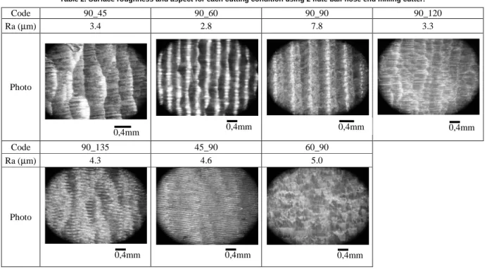
Tables 2 and 3 show the results of roughness as a function of the reference angles using two different ball-nose end milling cutters. Those tables also show a photo of each machined surface.
Table 2. Surface roughness and aspect for each cutting condition using 2 flute ball-nose end milling cutter.
Code 90_45 90_60 90_90 90_120
Ra (µm) 3.4 2.8 7.8 3.3
Photo
Code 90_135 45_90 60_90
Ra (µm) 4.3 4.6 5.0
Photo
Table 3. Surface roughness and aspect for each cutting condition using 4 flute ball-nose end milling cutter.
Code 90_45 90_60 90_90 90_120
Ra (µm) 4.2 4.3 3.4 4.2
Photo
Code 90_135 45_90 60_90
Ra (µm) 4.1 7.0 4.2
Photo
0,4mm 0,4mm
0,4mm 0,4mm
0,4mm
0,4mm 0,4mm
0,4mm
0,4mm 0,4mm 0,4mm
0,4mm
Figure 3 shows the FRF for robot arm alone on the position ready to the start cutting and with all joints locked, just before the contact between tool and workpiece in the X and Y directions.
All the FRF graphs are shown with the same scale for a better visual comparison. There are high magnitudes at 29 and 37 Hz for X direction and 25 and 31 Hz for Y direction, which are the natural frequencies. That indicates the system is willing to vibrate in this frequency when stimulated by the milling forces (Altintas, 2000). Such low frequencies seem to be originated from the low
stiffness of the joints and, according to Zengxi et al. (2006), this is a characteristic of robot arms. Looking at Fig. 3 it is also possible to see that both directions have similar magnitudes in frequencies very close to each other. The estimated values for damping ratio and dynamic stiffness, for both directions, indicate very flexible and highly damped structure. When the milling head is added to the system an additional high magnitude appears around 550 Hz for both directions again, besides those already mentioned. Figure 4 shows these new FRF graphs.
Figure 5. FRF for the Z direction without the milling head.
(a) X direction (b) Y direction
Figure 3. FRF of the robot arm without the milling head prior to contact between tool and workpiece.
(a) X direction (b) Y direction
The magnitudes with the milling head mounted were higher indicating that dynamic stiffness became lower. Higher magnitudes appeared, around 25, 50 and 540 Hz indicating the differences when the milling head was added to the robot arm. That milling head made the whole structure less stiff and with new modes of vibration at higher frequency, although still in very close frequencies in both directions.
The highest stiffness, however, was found in the Z direction, which was expected by the configuration of the robot arm during the milling operation. The arm is also very much contracted close to the robot base. Figure 5 shows the FRF for Z direction.
Overall, it appears that during the cut the whole robot structure, trying to position the joints, may have led the tool tip to oscillate around the straight programmed path. In addition, the
lateral stiffness, lower in both X and Y directions, seemed to have facilitated the slippage phenomenon. When using the tool at positions closer to the perpendicular one, it seems to be the best opportunities to improve surface quality, since that is closer to the stiffest position of the whole mechanical system.
The excitation frequencies given by the passing teeth touching the workpiece was 866 Hz and 1733 Hz for the 2 and 4 flutes, respectively. Although it not shown here, above 1000 kHz there was no significant amplitude, which could indicate chatter caused by tooth passing excitation. For the majority of the cutting conditions the marks on the machined surface were not uniformly distributed, as illustrated in Fig. 6.
Figure 7 shows the profiles obtained from this cutting condition.
Figure 6. Detail of surface obtained by 90_45 condition.
Figure 7. Profiles for 90_45 condition.
When Figs. 6 and 7 are examined one can see that there is no easily recognizable pattern of vibration on the profiles, which confirms deviation from the cutting path and not characteristic chatter marks.
The change from 2 to 4 flutes intended to use lower feed per tooth and, consequently lower forces, according to well established chip formation theories. The lower force had little influence of the surface roughness, at least within the range tested. It appears that the range was not large enough to cause the
surface finish to be improved by this factor. When working with lower feed per tooth the path deviation and high roughness were still high, except for the 90_90 situation.
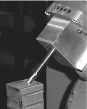
The 90_90 is a particular situation with less susceptibility to twist the milling head and maximum stiffness, which leads to produce a surface more typical of a machine tool with both tools. On the second application a semi sphere was machined to confirm the capability of machining complex shapes. Figure 8 shows the set up and the resulting shape after machining.
Feed direction
0.4mm
(a) General view of the machining set up (b) Detail of the machined surface
Figure 8. Resulting semi sphere after being machined in foam.
It can be emphasized that the semi sphere resulted in a very smooth surface and with all the facilities due to the 6 axis the machining operation was easily performed. The resulting surface was a typical one obtained from machine tools. That occurred because the material is very soft and cutting forces were very low and no path deviation occurred. The negative aspect of the dynamic instability of the structure was overcome by using a very soft material, as well as using user friendly software to generate the CL file (RobotStudio™). Sphere diameter resulted in less than 0.5 mm error and access was limited by the vise used. More of the sphere could have been produced with a less intrusive fixing system than the one that was used.
Conclusions
From the experimental tests and analysis performed, the following conclusions can be drawn:
• The best tool positions to machine aluminum alloy AA2024 using robot arms and ball-nose end milling cutters seem to be those closer to the normal one. Typical surface roughness was around 4 µm Ra with texture close to a typical milled surface. Lower roughness can be achieved with different angles, but random forms caused by slippage phenomenon are most likely to be present;
• Within the tested cutting conditions, there was little difference in roughness between 2 and 4 flute ball-nose end milling cutters. In general, lateral stiffness was very low and movements of the arm to positioning the tool as commanded may have aggravated the path deviation (slippage) and worsened the surface roughness;
• The rough surface obtained with aluminum alloy resulted, mainly, from deviation of the cutting edge from the defined path, as a consequence of low stiffness of the whole structure. That was more evident when the tool was not perpendicular to the machined surface, which increased the component forces on X and Y directions. Those directions have the lowest stiffness of all;
• When machining very soft materials such as foam for prototyping purposes, the robot arm showed excellent and typical characteristics of a very good machine tool. Surface finishing was very smooth and a complex shape such as a semi sphere was easily machined within 0.5 mm surface error with the robot used.
Acknowledgements
The authors would like to thank CNPq – Conselho Nacional de Desenvolvimento Científico e Tecnológico, CAPES – Coodenação de Aperfeiçoamento de Pessoal de Nível Superior, Projects PROCAD and PRO-ENG, and FAPESP – Fundação de Amparo à Pesquisa do Estado de São Paulo for scholarships and grants to researchers in this Field and also ABB for assistance and supply of robot software.
References
Abele, E., Weigold, M., Rothenbücher, S., 2007, “Modeling and Identification of an Industrial Robot for Machining Applications”, Annals of the CIRP, Vol. 56, No. 1, pp. 387-390.
Altintas, Y., 2000, Manufacturing Automation: Metal Cutting Mechanics, Machine Tool Vibrations and CNC Design, 1st Edition, Cambridge University Press, NY, USA.
Antunes, S., Coolec, T.J., Cheshirea, D.G., Pires, A.R., 2003, “Analysis of multi-axis milling in an anthropomorphic robot using the design of experiments methodology”, Journal of Materials Processing Technology, No. 135, pp. 235-241.
Batista, M.F., 2006, “Estudo da Rugosidade de Superfícies Plana Usinadas por Fresas de Topo Esférico” (Study of Roughness in Flat Surfaces Machined by End Mills), Master Thesis, The University of São Paulo, USP-EESC, 106 p. (In Portuguese).
Capla, R.L., 2006, “Estudo da Influência do Sobremetal Excedente de Desbaste na Operação de Acabamento Aplicando a Tecnologia de Usinagem com Altas Velocidades-HSM (Studying the Influence of Excessive Stock Left by Rough Operations on the Finishing One Applying the High Speed Machining-HSM Technology) Master Thesis, The University of São Paulo, USP-EESC, 106 p. (In Portuguese).
Cezary, Z., Krzysztof, M., Kazimierz, N., Wojciech, S., 2003, “A prototype robot for polishing and milling large objects”, Industrial Robot:
An International Journal, Vol. 30, No. 1, pp. 67-76.
Chin J.-H., Tsai H.C., 1993, “A path algorithm for robotic machining”,
Robotics & Computer-Integrated Manufacturing, Vol. 10, No. 3, pp. 185-198.
Fei R., Yuwen S., Dongming G., 2009, “Combined reparameterization-based spiral toolpath generation for five-axis sculptured surface machining”, International Journal of Advanced Manufacturing Technology, No. 40, pp. 760-768.
Huang, H,-K., Lin, G.C.I., 2002, “Development of a dual-robot system for prototype production”, International Journal of Production Research, Vol. 40, No. 15, pp. 3751-3764.
Ning, L., Martin, L., Andrew, W., 2005, “Surface finish visualisation in high speed, ball nose milling applications”, International Journal of Machine
Tools and Manufacture, No. 45, pp. 1152-1161.
Oberg, E. et al., Machinery’s Handbook, 2004, 27th Edition, Industrial Press Inc., New York, NY, USA.
Oliveira, J.F.G., Valente, C.M.O., 2004, “Fast Grinding Process Control with AE Modulated Power Signals”, Annals of CIRP, Vol. 54, No. 1, pp. 121-128.
Sabri, C., Ray-long, T., 1990, “Position error compensation of robotic contour end-milling”, International Journal of Machine Tools Manufacture, Vol. 30, No. 4, pp. 613-627.
Schaaf, W., 2000, “Robotyping - new rapid prototyping processes for sand moulds using industrial robots”, Assembly Automation, Vol. 20, No. 4, pp. 321-329.
Yuyao L., Jingchun F., Yuhan W., Jianguo Y., 2009, “Variable-period feed interpolation algorithm for high-speed five-axis machining”, International
Journal Advanced Manufacturing Technology, No. 40, pp. 769-775.