Theoretical Analysis of Formation and Sustainment
Methods for Compact Toroids
Ricardo Farengo, Agust´ın F. Lifschitz, Hugo E. Ferrari, Sebasti´an Bouzat,
Centro At´omico Bariloche e Instituto Balseiro, 8400 S. C. de Bariloche, RN, Argentinaand Roberto A. Clemente
Instituto de F´ısica Gleb Wataghin, Universidade Estadual de Campinas, 13083-970 Campinas, Brazil
Received on 19 January, 2004; revised version received 21 April, 2004
Recent theoretical studies on the use of neutral beams (NB), rotating magnetic fields (RMF) and helicity injec-tion (HI) to form and sustain compact toroids are reported. A Monte Carlo code was employed to study NB injection in Field Reversed Configurations (FRC) and Spheromaks. The code calculates the ionization of the neutral particles and follows the exact orbits of the ions. The magnetic field and density profiles are determined by solving a Grad-Shafranov equation that includes the beam current. RMF current drive in FRCs was studied using a fully 2D code that solves the two fluid equations with massless electrons and uniform temperature. The ion momentum equation includes viscosity and collisions with electrons and neutrals. The electrons are descri-bed using an Ohm’s law with the Hall and pressure gradient terms. Ion spin up due to collisions with electrons reduces the current drive efficiency and a large fraction of neutrals is needed to keep the azimuthal ion velocity small. The principle of minimum rate of energy dissipation was employed to calculate relaxed states for a flux core spheromak sustained by helicity injection. States with large regions of closed flux surfaces and significant toroidal current were found. Changing the resistivity profile modifies the safety factor profile, which can change from one that has a maximum at the magnetic axis (for uniform resistivity) to a tokamak-likeq-profile.
1
Introduction
Although the tokamak is the most advanced magnetic confi-nement concept, a commercial power plant utilizing a stan-dard tokamak would be large and expensive and have a rela-tively high electricity cost. The recognition of this problem has prompted, in recent years, a renewed interest in concepts that have lower development costs and could result in smal-ler, less expensive, reactors. A family of toroidal devices, generically known as Compact Toroids (CT), could satisfy these requirements.
Compact toroids are defined as toroidal configurations that have no structural elements linking the torus. Their aspect ratio is 1 and offer the possibility of translating the configuration after formation. Compact toroids can operate with high values ofβand are ideally suited to burn advanced fuels that produce fewer, or no neutrons. The different con-figurations are classified according to the ratio between the toroidal and poloidal fields. The most advanced CTs are the Field Reversed Configuration (FRC) [1] and the Speromak [2]. FRCs are elongated, have negligible toroidal field and operate withβclose to 1. Spheromaks have toroidal and po-loidal fields of the same order, produced by plasma currents, and lower values ofβ.
The development of efficient formation and sustainment methods is a key issue for all magnetic confinement con-cepts, in particular CTs. In standard tokamaks, start-up and
long pulse operation can be achieved using only the ohmic heating (OH) coil but the topology of CTs prevents the use of a central solenoid.
The traditional method used to form FRCs, field rever-sedθ-pinch, requires high voltages and does not appear sca-lable to reactor-size configurations. In addition, this method can not be used to sustain the configuration after formation. The most promising method to form and sustain FRCs is ro-tating magnetic field (RMF) current drive. This method has been used to produce cold rotamak configurations [3] and is currently under investigation in larger, more energetic, de-vices at the University of Washington [4]. Neutral beams (NB) could be used to form an FRC, to sustain the current and/or to heat the plasma. In addition, the use of beams to improve the stability of FRCs has been also proposed. The ARTEMIS [5] reactor design involves the use of beams and initial experiments with a 10 keV, 10 A neutral H beam have been performed [6].
Although various methods for spheromak formation and sustainment have been demonstrated, helicity injection (HI) has been the most successful [2]. DC HI is currently em-ployed in the SSPX spheromak [7] and AC HI is emem-ployed in HIT-SI [8]. Since HI current drive relies on relaxation, the calculation of relaxed states consistent with the boun-dary conditions needed for HI is clearly of interest.
sus-tain FRCs and Spheromaks. The structure of the paper is as follows. In section 2 we consider NBI in FRCs and Sphero-maks; in section 3 the use of RMFs to sustain the current in FRCs is analyzed and in section 4 relaxed states for a flux core spheromak sustained by helicity injection are presen-ted. Finally, in section 5, we summarize and discuss our results.
2
Neutral Beam Injection in FRCs
and Spheromaks
Neutral beam injection is one of the methods proposed to sustain the current in FRCs. It could be used alone or com-bined with RMF to cancel the torque transferred by the RMF driven electrons to the ions. Neutral beams have been injec-ted in the FIX device [6] but, do to the low magnetic field, the beam was directed primarily in the axial direction and confined by strong end mirrors. In addition, the lifetime of the experiments was much shorter than the slowing down and thermalization times, thus limiting the driven current and the deposited power. Spheromaks are generally formed and sustained by helicity injection and alternative methods are usually not considered. However, using NBI to drive part of the current could reduce the amplitude of the fluctua-tions needed to sustain the configuration, thus improving the confinement, and provide additional control over the current profile. Finally, injecting NBs in FRCs and Spheromaks will heat the plasma and provide a population of energetic parti-cles that could improve the stability of both configurations.
To study NBI current drive and heating in compact to-roids a Monte Carlo code was developed. Assuming a con-tinuous injection of neutral particles the code calculates their ionization and follows the exact trajectories of the ions. This information is used to reconstruct the spatial distribution of the beam density, current and transferred power and mo-mentum in steady state. The effect of Coulomb collisions is introduced via a Fokker-Planck collision operator. The magnetic field and density profiles needed to calculate the orbits and the stopping are determined by solving a Grad-Shafranov equation that contains the contribution of the beam to the total current but not to the pressure. The equi-librium and the beam current are calculated iteratively, ke-eping constant the average plasma density, and the poloidal plasma current in the case of Spheromaks, until the solution converges. The relevant beam variables are the axial posi-tion (where the beam is injected), the injecposi-tion angle (α), the neutral injection current (IN), the energy of the beam par-ticles (EN) and the impact parameter (b). Fig. 1 presents a schematic diagram showing the injection geometry.
beam
rs
z y
x
b beam
Figure 1. Injection geometry for FRCs.
2.1
FRCs
Studies for conditions similar to the best ones achieved in experimental devices [9] show the feasibility of using NBI for current drive in FRC. Fig. 2 shows the spatial distribu-tion of beam current and the flux surfaces for a low current beam (IN = 1A) and a high current one (IN = 300A) in-jected in an equlibrium with a racetrack-like separatrix and a hollow current profile. The FRC parameters are: separa-trix radiusrs = 30cm, lenghtzs = 240cm, external field
Bext = 5kG and temperaturesTe = Ti = 0.5keV. The beam is injected at the midplane, perpendicular to the FRC axis and has an energy (EN)of20keV. In the low current case the beam spreads over all the length of the FRC due to diffusion produced by collisions with the plasma ions. The beam current has a double peaked radial profile due to the radial oscillation of the particles around the magnetic null. In the high current case there is a significant change in the FRC equilibrium. The beam current increases the magnetic field near the injection region, producing a self-confining ef-fect which reduces the axial excursion of the deflected beam ions. Due to the highβ, the increase in the magnetic field around the injection region produces a similar increase in the density. Since the stopping increases with the density, the beam current increases slower than linear withIN.
0 30 -100
0 00
100 200 0
-100 0
00 0.1
30
r (cm) z (cm)
r (cm) z (cm)
I =300 A I =1 A
(b)
beam current
flux beam current
(a)
flux N
N
b b
j (A cm )−2 j (A cm )−2
18 20 22 24 26 20
25 30 35 40 45 50 55 60 65 70 75
Ionized part
icles (%)
b (cm)
α=90°
α=85°
α=80°
α=70°
α=60°
18 20 22 24 26
0 10 20 30 40
Deposit
ed power (%)
b (cm)
α=90°
α=85°
α=80°
α=70°
α=60°
18 20 22 24 26
0,0 0,1 0,2 0,3 0,4 0,5
Efficie
n
c
y (kA/A)
b (cm)
α=90°
α=85°
α=80°
α=70°
α=60°
(b) (a)
(c)
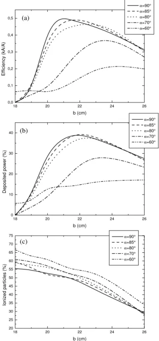
Figure 3. Current drive efficiency (3.a), deposited power (3.b) and fraction of ionized particles (3.c) as a function of the impact para-meter (b) for selected values ofα.
In recent studies, NBI into the TCS device [4] was consi-dered. In TCS, FRCs are formed and sustained using RMF and have lower magnetic fields (than in the studies repor-ted above) and higher χs (χs = rs/rw ≈ 0.8−0.9, rw
wall radius). These two facts restrict the allowable range of energies and the injection geometries. Our calculations show that for energies of10keV or more Deuterium beams can not be trapped. Hydrogen beams were therefore em-ployed in the calculations. Another factor affecting beam confinement is the presence of the transverse rotating mag-netic field that allows particles to move radially and collide with the wall. We show here the results for the best condi-tions predicted for TCS, i.e. external fieldBext = 750G,
T = 140eV, peak plasma densitynpeak= 0.5×10¹⁴
cm−3,
andχs= 0.8. The loss of particles through the ends is pre-vented by including magnetic mirrors, with a mirror ratio of 2.7. This value is large enough to reflect almost all the par-ticles that reach the mirror region. Beams injected through the ends and almost tangentially (angle with respect to the FRC axisα ≈ 30◦) do not drive a significant current and
deposit less that 5%of their power into the plasma, due to loss of particles by collisions with the wall. In the cases pre-sented below the beams are injected at the midplane with an energy of 10 keV.
Figure 3 shows the current drive efficiency (3.a), the de-posited power (3.b) and the fraction of ionized particles (3.c) as a function of the impact parameterbfor selected values ofα. For perpendicular injection (α = 90◦) the efficiency
and the deposited power present a maximum around 21 cm, close to the null radiusr0≈20.5cm. As the angle is
redu-ced, the maximum shifts toward larger values of the impact parameter. Forαbetween80◦and90◦the maximum values
of the efficiency and the deposited power remain approxi-mately constant at 0.5 kA/A and42%respectively. Particles injected with smallbare trapped in orbits that get very close to the wall and collide with it after few collisions, or even hit the wall before being deflected at all. This loss of particles causes a reduction of the efficiency forb <18cm in spite of the fact that for these values ofbthe ionization fraction is the largest (Fig. 3.c). Whenbis larger than 22-23 cm, the frac-tion of ionized particles decreases rapidly due to the lower plasma density encountered by the neutral beam particles. This results in a reduction of the current drive efficiency and the deposited power.
To explore the effect of the RMF, we included in the si-mulation a transverse rotating field. Approximate analytical expressions, taken from Ref. [10] were employed for the ra-dial dependence of the RMF field, no axial dependence was included. The RMF is determined by three parameters, the field magnitude outside the separatrixBω, the penetration rangeδand the rotation frequencyω. Fig. 4 shows the effici-ency as a function ofBω(4.a),δ(4.b) andω(4.c). The axial FRC field is 750 G. For a rotation frequency of 1 Mrad/s and a small penetration rangeδ = 0.1rs(fig. 4.a), the ef-ficiency decreases rapidly forBω >40G, dropping to less than 10%of the value without RMF forBω = 100G. The efficiency also decreases with the penetration rangeδ(4.b). The dependence with the rotation frequency is more com-plex (4.c). Forω = 0(Bω = 50 G andδ = 0.1rs), the efficiency is roughly 60%of the value without RMF and decreases sharply forω≈5×10⁶
s−1. This is due to a
0 2 4 6 8 10 12 14 16 18 0,0
0,1 0,2 0,3 0,4 0,5 0,6 0,7
without RMF
δ=0.1 rs Bw=50 G
Bext=750 G
Efficiency (kA/A)
ω (Mrad/s)
0,05 0,10 0,15 0,20 0,25 0,30 0,0
0,1 0,2 0,3 0,4 0,5 0,6 0,7
without RMF
ω=1 Mrad/s Bw=50 G Bext=750 G
Efficiency (kA/A)
δ/rs
0 20 40 60 80 100
0,0 0,1 0,2 0,3 0,4 0,5 0,6 0,7
without RMF
ω=1 Mrad/s
δ=0.1 rs Bext=750 G
Efficiency (kA/A)
Bω (G)
(a)
(b)
(c)
Figure 4. Efficiency as a function ofBω(4.a),δ(4.b) andω(4.c).
2.2
Spheromaks
The plasma is considered to be inside a flux conserver of radiusRs and height Zs, and the polodal flux is taken to be zero at the boundary. The injection geometry is shown in Fig. 5. The results presented here were obtained with
rs = zs = 50 cm, r0 = 31 cm, n = 10
14
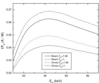
cm−3, Te = Ti = 0.5 keV,Bext = 7kG and a peaked density profile [11]. The current driven by the beam is the beam cur-rent minus the electron cancellation curcur-rent, which is due to the drag of plasma electrons by the beam. The maximum cancellation occurs at the magnetic axis, where there are no electrons trapped in banana-like orbits. Fig. 6 shows the to-tal driven current per unit of injected power. The curves for
Zef f = 1andZef f = 1.86are displayed. The current pre-sents a broad maximum around 40 keV. The beam current is higher forZef f = 1than forZef f = 1.86, but the total dri-ven current is lower in the former case. The reduction of the
plasma effective charge does not result in an improvement in the total current drive efficiency because the reduction of the stopping cross section is compensated by an increase in the electron cancellation current.
x
y
beam b
Z /2s s
z
R
Figure 5. Injection geometry for spheromaks.
20 40 60 80
0.02 0.03 0.04 0.05 0.06 0.07
I/P
N
(
A
/ W
)
EN (keV)
Beam Zeff=1.86 Beam Zeff=1. Driven Zeff=1.86 Driven Zeff=1.
Figure 6. Total driven current per unit of injected power as a func-tion ofEN.
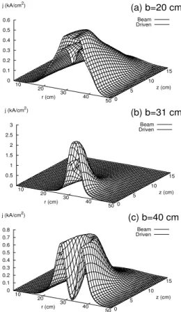
The beam current profiles are broad for injection with
b < r0, concentrated around the magnetic axis forb = r0
and hollow forb > r0 (Fig. 7). The electron cancellation
current is larger for b = r0 because the beam
concentra-tes in the region with the smallest fraction of trapped elec-trons. For lowZef f, the cancellation current is almost half the beam current. The safety factor profiles of the self-consistent equilibria show a clear sensitivity to the impact parameter (Fig. 8). Whenb =r0, the current concentrates
around the axis thus reducingq0. Whenb > r0, the hollow
current profiles increasesq0. Finally, whenb < r0there is a
be controlled even with the simple injection geometries em-ployed here, where onlybis allowed to change. For injection below the magnetic axis (b < r0), the power is deposited in
a broad region that becomes more concentrated around the axis asbapproachesr0. Forb > r0the profile is hollow and
the power deposited in the plasma core is small.
Beam Driven
10 20
30 40
50
r (cm) 0
5 10
15
z (cm) 0
0.1 0.2 0.3 0.4 0.5 0.6 j (kA/cm2)
Beam Driven
10 20
30 40
50
r (cm) 0
5 10
15
z (cm) 0
0.5 1 1.5 2 2.5 3 j (kA/cm2)
Beam Driven
10 20
30 40
50
r (cm) 0
5 10
15
z (cm) 0
0.1 0.2 0.3 0.4 0.5 0.6 0.7 0.8 j (kA/cm2)
(c) b=40 cm (b) b=31 cm (a) b=20 cm
Figure 7. Spatial distribution of the current density for different values of the impact parameter.
0.0 0.2 0.4 0.6 0.8 1.0
0.0 0.2 0.4 0.6 0.8 1.0
q
(r-r 0)/(Rs-r0)
Without beam b=31 cm b=20 cm b=40 cm
Figure 8. Safety factor profiles for different values of the impact parameter.
3
Rotating Magnetic Field Current
Drive
Extensive theoretical studies of RMF current drive in FRCs have been performed in the last 20 years [12]-[15]. Howe-ver, none of these studies has included the full ion dyna-mics in a time dependent calculation. Although ideally the RMF drags only the electrons, it is clear that electron ion collisions will accelerate the ions in the azimuthal direction, thus reducing the total current. It is therefore important to study ion acceleration, its effect on the equilibrium, and the mechanisms that can prevent it. We studied the effect of ion motion on RMF current drive in FRCs using a 2D (r,θ) numerical code that solves a set of equations forAz, Bz, the three components of the ion velocity and the density (ne = ni). Viscosity and collisions with neutrals, which remain fixed, were included in the ion momentum equation. In fixed ion calculations there are only two dimension-less parameters: λ = rs(µ0ω/2η)
1/2
andγ = Bω/enη, whereη is the resistivity. When the full ion dynamics is included new dimensionless parameters appear in the equa-tions. They are: δ = 2T en0µ0/miωBω,Ω = eBω/miω
andB0 =Bext/Bω. The boundary conditions imposed at
the plasma vacuum interface are: continuity of∂Az/∂rand
∂viθ/∂r,vir = 0,∂viz/∂r = 0and∂n/∂r = 0. In the calculation of the efficiency the maximum current is defined with the ions fixed.
For values of γ andλwhich result in full penetration of the RMF and synchronous electron rotation the ions ac-celerate in the azimuthal direction and their final velocity depends on the fraction of neutrals (fn=n/nneutrals). For the parameters considered (γ = 20, λ = 11, δ = 2.9,Ω = 0.2andB0= 3),viθ/vrmf = 0.08and0.45forfn = 50%
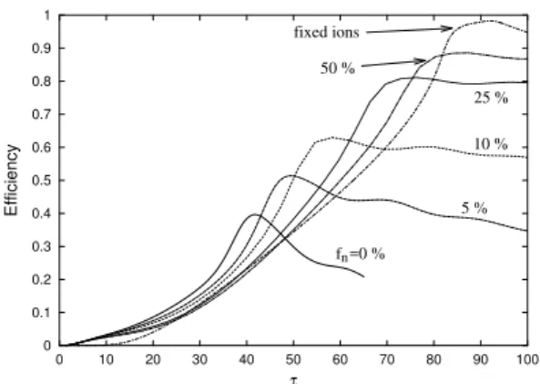
and10%respectively (vrmf: velocity for synchronous rota-tion). Ion rotation reduces the efficiency (current). This is shown in Fig. 9, which presents a plot of the efficiency as a function of normalized time (τ=ωt) for different fractions of neutral atoms and also for fixed ions. The dimensionless parameters are the same as above. There are two stages. In the first stage the efficiency grows and in the second one it decays (fn < 10%) or remains approximately constant. The fastest initial growth is obtained when the are no neu-trals and the slowest one when the ions remain fixed. The faster initial growth obtained with the smaller values offn
is the result of two effects. First, the ions rotate as a rigid ro-tor across the entire cross section due to their viscosity. This means that the ions rotate in regions where the RMF has not yet penetrated. Second, the centrifugal force pushes the ions outwards reducing the density inside the plasma and increa-sing the effectiveγseen by the RMF. Since the highestviθ
0 0.1 0.2 0.3 0.4 0.5 0.6 0.7 0.8 0.9 1
0 10 20 30 40 50 60 70 80 90 100
Efficiency
τ
n
f =0 %
5 % 50 %
fixed ions
25 %
10 %
Figure 9. Efficiency as a function of time for different values of the fraction of neutrals and for fixed ions. γ=20,λ=11,δ=2.9,Ω=0.2
B0=3.
Whenγis below the value corresponding to full pene-tration, the efficiency can be higher for moving ions and va-riable density than for fixed ions. Fig. 10 shows the time evolution of the efficiency forγ= 14,λ= 11and the other parameters as in Fig. 9. The efficiency obtained including ion motion, andfn = 50%,25%and10%, is higher than the efficiency of the fixed ion model. This increase in the effici-ency is due to a growth in the penetration range which is not overcomed by ion rotation whenfn > 10%. As the RMF penetrates, the ions begin to rotate everywhere and centri-fugal effects reduce the density at the center of the plasma column. The density reduction increases the local value ofγ
actually seen by the RMF above the critical value needed for penetration. This process allows the system to access steady states with large penetration and high density at the edge that,a priori, could have been considered unaccessibles.
0 0.1 0.2 0.3 0.4 0.5 0.6
0 50 100 150 200 250 300
Efficiency
τ
n
f =0 %
fixed ions 5 %
10 %
25 %
50 %
Figure 10. Efficiency as a function of time for different values of the fraction of neutrals and for fixed ions. γ=14, λ=11, δ=2.9,
Ω=0.2B0=3.
When the ion rotation is large enough and the radial density profile has a maximum inside the plasma an azi-muthal distortion appears. This is due to an internal (the plasma boundary is fixed) rotational instability. Forγ= 20,
λ = 11,δ = 0.8,Ω = 0.2,B0 = 3andfn = 10%the
n=1 mode appears whenviθ/vther ≈1.4and the n=2 mode whenviθ/vther≈1.7.
4
Relaxed States for a Flux Core
Spheromak Sustained by Helicity
Injection
Helicity injection current drive is generally explained by assuming that the plasma undergoes some form of relaxa-tion that allows for a redistriburelaxa-tion of the magnetic flux. Although the minimum energy principle [16] has been suc-cessful at explaining some basic features of space and la-boratory plasmas, its use in driven systems has been ques-tioned by many authors. In such systems, other principles that allow for the introduction of balance constraints, the use of boundary conditions that include the basic features needed for helicity injection and the inclusion of non uni-form/anisotropic resistivity effects could be more appropri-ate. We employed one such principle, the principle of mi-nimum rate of energy dissipation, to calculate relaxed states of a spheromak sustained by helicity inejction [17]. More specifically, we minimized the Ohmic dissipation rate with the constraints of helicity balance (injection rate=dissipation rate) and∇ ·B=0. The resulting Euler-Lagrange equation was solved numerically (in 2D) using boundary conditions that include the basic features of the experimental situation.
V/2
-V/2
a
L
B
extb
I
extElectrode
Figure 11. Configuration considered in the calculation of minimum dissipation states.
with radiusb, and the entire configuration is axisymmetric (∂/∂θ ≡ 0). We assume that a set of external coils, not shown in the figure, produce a uniform axial magnetic field (Bext ) on both electrodes. The external field at the trodes, the voltage and the current flowing through the elec-trodes are considered external parameters that can be varied independently. The resistivity was considered isotropic but non uniform.
Two types of relaxed states, both with large regions of closed flux surfaces, were found: one has a central core for-med by the flux that links the electrodes surrounded by a toroidal region of closed flux surfaces and the other has the open flux wrapped around the closed flux surfaces. Flux contours for both types of solutions are shown in Fig. 12 for V = 600(V = Vinjµ0/|Bext|η0), I = 0.72 (I =
µ0Iext/aπ|Bext|) and uniform resistivity (η0= 10− 6
Ωm). In Fig. 12a,λa= 3.9228while in Fig. 12b,λa= 4.2948.
The solutions shown in Figs. 12a and 12b have, respecti-vely,λ < λeigenandλ > λeigen, whereλeigena= 4.0679
and corresponds to the solution withj.ˆn=0 everywhere at the boundary. These solutions are relative minima of the dissipation rate and the maximum corresponds to the limit when the injection and dissipation rates go to infinity and
λ→λeigen. The results presented below haveV = 600and
I = 0.72and correspond to the case with the open flux on the inside, which is the interesting one for the experiments.
b) a)
0 .0 0 .2 0 .4 0 .6 0 .8 1 .0 -1 .0
-0 .5 0 .0 0 .5 1 .0
z/
a
r /a
0 .0 0 .2 0 .4 0 .6 0 .8 1 .0 -1 .0
-0 .5 0 .0 0 .5 1 .0
z/
a
r /a
Figure 12. Flux contours for both types of solutions. (a)
λa=3.9228, (b)λa=4.2948.
Since the FCS contains regions of open and closed flux surfaces a resistivity profile that depends on the poloidal flux was employed:η=η0 [1 +|ψ|/|ψs|]αin the open flux
re-gion andη =η0 [2−1.5 (|ψ| − |ψs|)/|ψ0|]αin the closed
flux region, whereψsandψ0, are, respectively, the poloidal
flux at the separatrix and at the magnetic axis. The parame-terαcontrols the resistivity gradient (α= 0gives uniform resistivity). Fig. 13 shows resistivity profiles at the midplane (z= 0) obtained forα= 0,0.5,1and2. As expected, when
α6= 0, the resistivity is maximum at the separatrix and mi-nimum at the magnetic axis. Fig. 14 shows radial profiles of
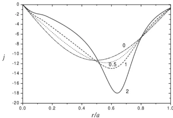
j(j =jθµ0a/|Bext|) for the same conditions as in Fig. 13.
Asαincreases, the toroidal current density becomes more peaked and the maximum absolute value shifts outwards.
Finally, Fig. 15. presents plots of the safety factor profile for the same conditions as in Fig. 13. For these calculations the safety factor profile is defined as:
q= 1
2π
I B
r Bp ds
whereBp is the normalized poloidal field and the integral is calculated following the field line around a single poloi-dal circuit. Whenα= 0, uniform resistivity,qis maximum at the magnetic axis and decreases towards the edge. Asα
increases, the value at the magnetic axis decreases rapidly while the edge value shows a slight reduction forα = 0.5
and1followed by an increase forα = 2. This changes in theq-profile are clearly related to the changes in the current profile and total current already discussed. Forα = 2, a 50% increase in the external current (toI= 1.08) increases the value ofqat the magnetic axis by 18% and the value at the edge by 22%.
0.0 0.2 0.4 0.6 0.8 1.0
0.0 0.5 1.0 1.5 2.0 2.5 3.0 3.5 4.0
2
1
0.5 0
η
r/a
Figure 13. Radial resistivity profiles atz = 0for different values
ofα.
0 .0 0 .2 0 .4 0 .6 0 .8 1 .0 -2 0
-1 8 -1 6 -1 4 -1 2 -1 0 -8 -6 -4 -2 0
0
0 .5 1
2
j
r/a
0 .6 5 0 .7 0 0 .7 5 0 .8 0 0 .8 5 0 .9 0 0 .9 5 1 .0 0 0 .4
0 .6 0 .8 1 .0 1 .2 1 .4
0
0 .5
1
2
q
r/a
Figure 15. Radial safety factor profiles for different values ofα.
5
Summary
We presented the results of theoretical analysis of three cur-rent drive methods which apply to CTs. It was shown that neutral beams can drive a significant current and modify the pressure profiles in high density,θ-pinch produced, FRCs. In lower density, lower field FRCs produced by RMF there are severe limitations to the energy of the neutral particles and the injection geometry. In addition, large reductions in efficiency occur if the amplitude and/or penetration of the RMF is too large. Neutral beams could provide significant control over the safety factor profiles of Spheromaks but ad-ditional studies are needed to determine the effect of fluctu-ations on beam trapping and the effect of relaxation on the beam current profile.
RMF current drive is very attractive for FRCs but methods to prevent ion spin-up must be developed. It was shown that electron-ion collisions accelerate the ions in the azimuthal direction and large fractions of, fixed, neutral atoms are needed to obtain reasonable current drive effici-encies. In addition, rotational instabilities appear when the azimuthal ion velocity becomes of the order of the thermal velocity. Two dimensional relaxed states of flux core Sphe-romaks sustained by helicity injection show a large region of closed flux surfaces and significant toroidal current. Chan-ging the resistivity profile modifies the safety factor pro-file, which can change from one that has a maximum at the magnetic axis (for uniform resistivity) to a tokamak-likeq -profile. Three dimensional calculations are needed to
deter-mine the values of the parameters where a helical relaxed state appears.
Acknowledgements
This work was partially supported by the Agencia Na-cional de Promoci´on Cient´ıfica y Tecnol´ogica of Argentina. One of the authors (RAC) would also like to thank finan-cial support from Conselho Nacional de Desenvolvimento Cient´ıfico e Tecnol´ogico (CNPq, Brazil). The contribution of A.L. Hoffman to the study of NBI in FRCs sustained by RMF is acknowledged.
References
[1] M. Tuszewskii, Nuclear Fusion28, 2033 (1988).
[2] T. R. Jarboe, Plasma Phys. Control. Fusion,36, 945 (1994).
[3] I. R. Jones, Phys. of Plasmas6, 1950 (1999). [4] A. L. Hoffman et al., Nucl. Fusion43, 1091 (2003).
[5] H. Momota et al.,Plasma Physics and Controlled Nuclear Fusion Research, IAEA, Viena, Vol. 3, p. 319 (1993).
[6] T. Asai et al., Phys. Plasmas7, 2294 (2000).
[7] E. B. Hooper, L. D. Pearlstein, and R. H. Bulmer, Nucl. Fu-sion39, 863 (1999).
[8] T. R. Jarboe, Fusion Technol.,36, 85 (1999).
[9] A.F. Lifschitz R. Farengo, and N. R. Arista, Nucl. Fusion42
(2002) 863.
[10] A. L. Hoffman, Nucl. Fusion40, 1523 (2000).
[11] A. F. Lifschitz, R. Farengo, and N. R. Arista, Plasma Phys. Control. Fusion44, 1979 (2002).
[12] R. D. Milroy, Phys. Plasmas,6, 2771 (1999).
[13] R. D. Milroy, Phys. Plasmas,7, 4135 (2000).
[14] W. N. Hugrass and R. C. Grim, J. Plasma Phys. 26, 455 (1981).
[15] W. N. Hugrass J. Plasma Phys.28, 369 (1982). [16] J. B. Taylor, Phys. Rev. Lett.33, 1139 (1974).
[17] R. Farengo and K. I. Caputi, Plasma Phys. and Contr. Fusion
44, 1707 (2002).