Abstract
In longitudinal multi-mode pushover analysis of bridges with ele-vated pile foundation systems, the inelastic contributions of the second mode cannot be neglected. Generalized pushover analysis cannot be applied directly in this condition. A modified general-ized pushover procedure is developed for estimating seismic de-mands of bridges with elevated pile foundation systems. Modified generalized pushover procedure, modal pushover analysis and incremental dynamic analysis of a bridge with elevated pile foun-dation systems are conducted. The results show that the modified generalized pushover procedure can provide reasonable estimations of moments and predict more accurate plastic hinge rotations compared with modal pushover analysis.
Keywords
Pushover analysis; Modified GPA; bridges with elevated pile foundation system; Contributions of higher modes; MPA.
Modified generalized pushover analysis for estimating longitudinal
seismic demands of bridges with elevated pile foundation systems
1 INTRODUCTION
For seismic evaluation of structures, nonlinear time-history analysis (NL-THA) could be used. However, NL-THA is time-consuming. As an efficient and economic method for seismic perfor-mance evaluation of structures, pushover analysis is favored by current structural engineers (Akhaveissy, 2012; Forcael, 2014).
Pushover analysis in many cases will provide much more relevant information than an elastic static or even dynamic analysis, while in some other cases it will provide misleading results (Krawinkler, 1996). Traditional pushover analysis procedures are conducted with common lateral force patterns, such as first mode, inverted triangular, uniform, etc (Applied Technology Council, 2005). The procedures are applicable for regular structures which vibrate primarily in the funda-mental mode. However, they are not suitable for irregular structures, in which the contributions of higher modes are significant (Krawinkler and Seneviratna, 1998).
S. Caoa W. Yuanb
Tongji University, Shanghai, China
Corresponding author: a[email protected]
Latin American Journal of Solids and Structures 11 (2014) 2696-2712
Multi-mode pushover analysis procedures have been proposed to consider contributions of higher modes. To include the influence of higher modes, Chopra and Goel proposed modal pusho-ver analysis procedure (MPA) (Chopra and Goel, 2002). In the procedure, a pushopusho-ver analysis is conducted for each mode separately, and then total seismic responses are computed by combining the responses due to each modal load. MPA produces the same results as response spectrum anal-ysis (RSA) when a structure vibrates in linear elastic range. Even when a structure responds well into inelastic range, MPA is capable of providing good estimates of displacement demands and identifying locations of plastic hinges. Moreover, implementation of MPA is simple. To save com-puting effort, Chopra et al improved MPA to develop modified MPA(MMPA) (Chopra, 2004). In the MMPA procedure, response contributions of higher modes are computed by assuming a struc-ture being elastic. SRSS combination rule is adopted by both MPA and MMPA to combine mod-al responses. There are severmod-al shortcomings of combining inelastic modmod-al responses by SRSS, especially when internal forces are calculated (Papanikolaou and Elnashai, 2005).
Adaptive pushover procedures have been proposed to capture the changing properties of struc-tures in pushover analysis (Antoniou and Pinho, 2004; Elnashai, 2001; Gupta and Kunnath, 2000). When a structure vibrates into inelastic range, its dynamic properties will change with time. In an adaptive pushover procedure, the lateral force pattern is updated according to the time-variant stiffness distribution of the structure. Antoniou and Pinho proposed a displacement-based adaptive pushover procedure (Antoniou and Pinho, 2004). In the procedure, a set of updat-ed lateral displacements, rather than force, are imposupdat-ed on the structure. Pushover procupdat-edures with adaptive lateral force patterns can provide more accurate dynamic response evaluations of structures. However, they are conceptually complicate and computationally demanding for rou-tine application in structural engineering practice.
Based on MPA, Kalkan and Kunnath proposed an adaptive modal combination procedure (AMC) (Kalkan and Kunnath, 2006). AMC is the same as MPA with the exception being that the modes are updated at each step of modal pushover analysis. AMC can reasonably predict critical demand parameters, such as roof displacement and inter-story drifts, for both far-fault and near-fault seismic records. However, the AMC procedure is quite complicated, and SRSS combination rule is still adopted.
Benchmark values to evaluate accuracy of pushover results are usually provided by incremen-tal dynamic analysis (IDA) (Vamvatsikos and Cornell, 2002). To obtain more accurate predic-tions through pushover analysis, it is necessary to analyze the relapredic-tionships between pushover analysis and IDA. Both pushover analysis and IDA use principles of equilibrium and compatibil-ity with the difference being that IDA equilibrium includes damping and inertia effects. The vari-able is current level of displacement or force in pushover analysis, while the varivari-able is time in dynamic analysis (Papanikolaou and Elnashai, 2005). Maximum values of various response pa-rameters generally happen at different instants in NL-THA. Hence, values of various response parameters are obtained at various instants in dynamic analysis. Consequently, they are in differ-ent equilibriums. However, values of response parameters of a structure are all obtained from a single equilibrium in a single-run pushover analysis. It is impossible to replicate all the inelastic response parameters of a dynamic analysis with a single-run pushover analysis.
Latin American Journal of Solids and Structures 11 (2014) 2696-2712
and Gunay, 2011), Sucuoğlu and Günay proposed generalized pushover analysis (GPA) proce-dure. Maximum value of a response parameter can be expressed by modal expansion in time do-main analysis. Meanwhile, it can also be expressed by quadratic combination (SRSS) of the relat-ed spectral modal responses. Constructing the equilibrium between the two expressions for a re-sponse parameter, a pair of GPA parameters (generalized force vector and target deformation demand) can be computed from RSA results of the structure. A generalized force vector corre-sponds to the inertial force vector of the structure at the instant when a specific response parame-ter reaches its maximum value in dynamic analysis. A target deformation demand corresponds to the maximum deformation in dynamic analysis of the structure. Generalized force vectors are applied to the structure separately in an incremental form until target deformation demands are attained. Maximum value of any response parameter is obtained from the envelope of the GPA results. GPA procedure is successful in estimating maximum deformations and member forces with reference to IDA results.
All the pushover procedures aforementioned are proposed for buildings. Paraskeva and Kappos have extended MPA for seismic assessment of bridges (Paraskeva, 2006). The adaption included “the selection of the appropriate control point, the way a pushover curve is bilinearized before being transformed into a capacity curve, the use of the capacity spectrum for defining the earth-quake demand for each mode and then combining modal responses, and the number of modes that should be considered in the case of bridges”. Biao Wei et al. have applied equal displacement rule to continuous bridges with long periods (Wei, 2014). Their work is mainly on applying MPA in the transverse direction of a curved bridge.
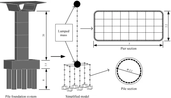
Elevated pile foundation systems (Figure 1) are widely used for deep water bridges. The sys-tem includes a group of long piles, a high-rise cap and a pier. When subjected to longitudinal excitation, superstructure of a straight bridge can be simplified to a lumped mass and the whole bridge can be simplified as a model shown in Figure 1. In the paper, all static and dynamic anal-yses are applied to the simplified model of the whole bridge.
Mass and stiffness distribution of the simplified model vary greatly in the vertical direction. Besides the first mode, second mode of elevated pile foundation system is easy to enter inelastic range even when subjected to moderate earthquake. In such a case, systematic errors of target deformation demands will occur if the second mode is treated as linear elastic in GPA procedure. Therefore, it should be confirmed that second mode, as well as the first mode, should be treated as inelastic in GPA procedure of the simplified model. GPA procedure proposed by Sucuoğlu and Günay considered inelastic contributions of the first mode only and couldn’t be directly applied to the simplified model. Uncoupled modal response history analysis (UMRHA) (Chopra, 2007) is a convenient method to compute the GPA parameters, when inelastic contributions of more than one mode needs to be included. Modified GPA is developed based on this idea.
Typically, first two or three modes will be enough (Chopra and Goel, 2002). Modified GPA is able to obtain the generalized force vectors with only the first two or three modes.
Latin American Journal of Solids and Structures 11 (2014) 2696-2712
and IDA of the elevated pile foundation system are conducted with an ensemble of 9 ground mo-tions. The response parameters predicted by modified GPA are compared with MPA results, as well as IDA results. Conclusions are presented accordingly at last.
2 MODIFIED GPA
GPA uses response spectrum analysis (RSA) results to determine the GPA parameters. Through RSA, GPA provides a smart way to capture the GPA parameters. Consequently, people don’t have to find out the exact instants when response parameters reach their maximum values indi-vidually.
Modified GPA uses UMRHA method to compute generalized pushover parameters. Having the capability of showing values of a response parameter in every step in time domain analysis, it is convenient to find out the instant when a response parameter reaches its maximum value in UMRHA procedure. Once all the instants are known, the GPA parameters can be computed by combining contributions of the uncoupled modes.
Two main characteristics of modified GPA are: (1) The GPA parameters are directly deter-mined through UMRHA; (2) Inelastic contributions of higher modes are convenient to be consid-ered.
2.1 The UMRHA-method to Determine the GPA Parameters
The differential equations governing seismic response of a structure can be uncoupled to several equations of effective SDOF systems (Chopra, 2007):
2 sn ( )
n n n n n g
n
F
q q u t
M z w
+ + = -G
(1)
Here, T
n n
L =j mi; Mn =jTnmjn; wn is natural vibration frequency; zn is damping ratio for
the nth mode; G =n Ln Mn is nth mode participation factor; jn is nth natural vibration mode of
the structure; ( , ) T ( , )
sn sn n n n s n n
F = F q sign q =j f u sign u is resisting force.
The resisting force depends on all modal coordinates q tn( ), implying coupling of modal coordi-nates because of yielding of the structure. Neglecting contribution of the other modes to the nth mode resisting force Fsn, Fsn now depends only on the nth-mode coordinate qn.
Eq. 1 now can be transformed to:
2 sn ( )
n n n n g
n
F
D D u t
L z w
+ + =
- (2)
where Fsn =Fsn(D sign Dn, n)= jTn sf D sign D( n, n); qn = GnD tn( ).
Latin American Journal of Solids and Structures 11 (2014) 2696-2712
( )
n
D t and A tn( )can be obtained by solving Eq. 2.
1 1
( ) ( ) ( )
N N
n n n n
n n
u t u t j D t
= =
=
å
=å
G (3)1 1
( ) ( ) ( )
N N
n n n n
n n
f t f t mj A t
= =
=
å
=å
G (4), , , 1
1 1
( ) ( ) ( )( )
N N
j j n n n n j n j
n n
t t D t j j
-= =
D =
å
D =å
G - (5)The nonlinear response histories of floor displacements u t( ) and interstory drifts Dj( )t can be obtained from Eq. 3 and Eq. 5. The instants tmax, when the target deformation demands reach their maximum values, can be obtained easily. Then, D tn(max) and A tn(max) can be obtained. Bring A tn(max) into Eq. 4, corresponding generalized force vectors can be computed. Compared with GPA in literature (Sucuoglu and gunay, 2011), modified GPA is straightforward and easy to implement.
Main errors of the UMRHA-method arise from neglecting the coupling of equations between modal responses. When a structure is subjected to weak excitation Peff n, ( )t , the response is in the nth-mode only, and all the other modes make no contribution. When a structure is subjected to strong excitation Peff n, ( )t , the other modes start responding to Peff n, ( )t after the instant when the
structure first yields. However, their contributions to the response are small (Chopra and Goel, 2011).
2.2 Main steps of the modified GPA
Main steps of the modified GPA can be summarized as following:
1. Eigenvalue analysis. Natural frequencies wn, natural periods Tn, modal vectors jn and the modal participation factors Gn are determined.
2. Pushover analysis. For the nth-mode, pushover analysis with the lateral force vector of *
n n
s =mj is conducted. The base-shear--roof-displacement (Vbn-urn) pushover curve is obtained. 3. Obtain Fsn Ln -Dn relationship. Pushover curves are idealized as bilinear curves. The ideal-ized pushover curves are converted to the Fsn Ln -Dn relationships.
4. Compute response history. The deformation history D tn( ) and pseudo-acceleration history ( )
n
A t of the nth-mode inelastic SDOF system are computed with force-deformation relationships developed in step 3.
5. Determine target displacement demands and corresponding tmax. Through the deformation histories computed in step 4, response histories of displacement demands are obtained with Eq. 3 or Eq. 5. Target displacement demands and corresponding tmax are directly captured.
6. Calculate generalized force vectors. Using the pseudo-accelerations A tn(max) computed in step 5, generalized force vectors are determined with Eq. 4.
Latin American Journal of Solids and Structures 11 (2014) 2696-2712 3 CASE STUDY
Modified GPA is verified through a simplified model of a bridge with elevated pile foundation systems, which has been used in the literature (Wancheng and Jun, 2008). The necessity of in-cluding inelastic contributions of the second mode is illustrated. Both modified GPA and MPA of the simplified model are conducted. To provide benchmark results, IDA of the simplified model is also conducted. The system is analyzed with 9 different ground motion components.
3.1 Simplified model of a bridge with elevated pile foundation systems
Simplified model of the elevated pile foundation system is shown in Figure 1. Superstructure is simplified as a mass and fixed to the top of pier. The pile cap is modeled as a mass and fixed to top of the piles and bottom of the pier. Equivalent cantilever pile model is adopted to represent the interaction between piles and soil (Chen, 1997). Piles are assumed to be embedded in ground with a predetermined depth. It should be noted that research on the interaction between piles and soil is still performed (Kim, 2011).
Figure 1: Elevated pile foundation system of bridges (m).
Latin American Journal of Solids and Structures 11 (2014) 2696-2712
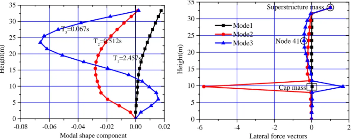
Simplified model of the bridge is constructed and analyzed by the open source software Open-Sees (Mazzoni, 2007). Piles and pier are simulated by the dispBeamColumn element, which is a distributed-plasticity, displacement-based beam-column element. Element length of piles and pier is settled to 2 m and each element includes 5 integration points since accurate determination of local response quantities requires a finer finite element mesh. Fiber sections with unconfined and confined concrete materials presented by Mander et al. are assigned to pier and piles. Plastic hinge rotations are integrated at integration points where curvature of the section exceeds elastic range (Usually at ends of pier and piles). Masses of superstructure and pile cap are fixed to struc-ture elements by rigid link. P-Delta effects are not included. Figure 2 shows the elastic modal shape of the elevated pile foundation system. Damping ratio of 0.05 is assigned to the simplified model through periods of the first and the second mode 2.457 s, 0.512 s, respectively. Modified GPA, MPA and IDA are conducted in the longitudinal direction of the bridge. Contributions of the first three modes are considered in the pushover analyses.
0 5 10 15 20 25 30 35
-0.08 -0.06 -0.04 -0.02 0.00 0.02 Modal shape component
T3=0.067s
T2=0.512s
H
eight(m)
T1=2.457s
0 5 10 15 20 25 30 35
-6 -4 -2 0 2
Lateral force vectors Superstructure mass Cap mass He igh t( m ) Mode1 Mode2
Mode3 Node 41
Figure 2: Elastic modal shapes and lateral force vectors of the elevated pile foundation system.
Pushover curves and their bilinear fits of the first 3 modes are shown in Figure 3. Fsn Ln -Dn
relationships of single degree of freedom(SDOF) systems corresponding to the first three modes are obtained from these bilinear fits.
0.0 0.1 0.2 0.3 0.4 0.5 0.6 0 200 400 600 800 1000 1200 1400 1600 Ba se sh e ar(k N) Target displacement(m) Pushover curve Bilinear fit
0.00 0.05 0.10 0.15 0.20 0 5000 10000 15000 20000 25000 B ase sh ea r(k N) Target displacement(m) Pushover curve Bilinear fit
0.00 0.02 0.04 0.06 0.08 0.10 0 5000 10000 15000 20000 25000 30000 B ase sh ea r(k N) Target displacement(m) Pushover curve Bilinear fit
a. Mode 1 b. Mode 2 c. Mode 3
Latin American Journal of Solids and Structures 11 (2014) 2696-2712
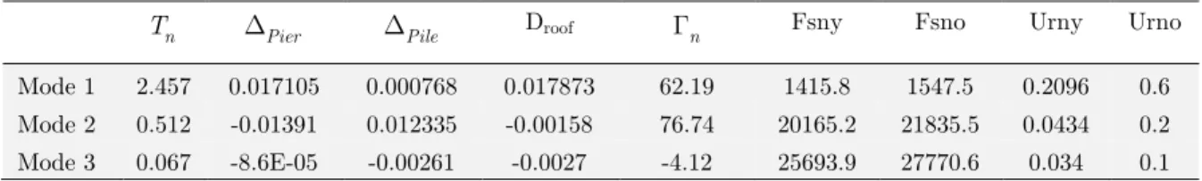
Modal properties of the first 3 modes are shown in Table1. These properties can be used to compute GPA parameters in MGPA procedure.
n
T DPier DPile Droof Gn Fsny Fsno Urny Urno
Mode 1 2.457 0.017105 0.000768 0.017873 62.19 1415.8 1547.5 0.2096 0.6 Mode 2 0.512 -0.01391 0.012335 -0.00158 76.74 20165.2 21835.5 0.0434 0.2 Mode 3 0.067 -8.6E-05 -0.00261 -0.0027 -4.12 25693.9 27770.6 0.034 0.1
Table 1: Modal properties of the first 3 modes.
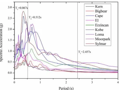
An ensemble of 9 earthquake ground motion records was selected for the case study, including both far-fault and near-fault ground motion records. Ensemble of the records is shown in Table 2. Spectral accelerations of the records are shown in Figure 4. In the records, the spectral accelera-tion achieves peak value at around the 2nd modal period (0.512 s). As a result, significant second mode effects are affected by the records. The ground motion records are downloaded from the PEER strong motion database and the COSMOS Virtual Data Center.
Short name
Year Earthquake Moment mag.
Mech.a Recording station Dist.b
(km) Site
Classc
Comp. PGA (g)
PGV (cm/s)
Far-fault ground motions
Kern 1952 Kern county 7.5 TH/REV Taft 36.2 D 111 0.18 17.50
Bigbear 1992 Big Bear 6.4 SS Desert Hot Spr.
(New Fire Stn.) 40.1 D 090 0.23 19.14
Moorpark 1994 Northridge 6.7 TH Moorpark
(Ventura Fire Stn.) 26.4 D 180 0.29 20.97
Near-fault ground motions
Erzincan 1992 Erzincan 6.7 SS Erzincan 2.0 C EW 0.50 64.32
Cape 1992 Cape
Mendo-cino 7.1 TH
Petrolia,
General Store 15.9 C 090 0.66 90.16
Loma 1989 Loma Prieta 7.0 OB Los Gatos
Parent Center 3.5 C 000 0.56 94.81
Sylmar 1994 Northridge 6.7 TH Sylmar Olive
View Hospital 6.4 D 360 0.84 170.37
Kobe 1995 Kobe 6.9 SS JMA 0.6 C 000 0.82 81.62
El 1940 El Centro 6.9 SS 117(UGUS) 12.2 D 180 0.35 33.45
aFaulting mechanism: TH-thrust; REV=reverse; SS=strike-slip; and OB=oblique.
bClosest distance to fault.
cNEHRP site classifications: [C for Vs (shear-wave velocity)=360-760 m/s], (D for Vs=180-360m/s).
Latin American Journal of Solids and Structures 11 (2014) 2696-2712
3.2 Necessity of Including Inelastic Contributions of the Second Mode
For a simplified model of a bridge with elevated pile foundation systems, the second mode may also enter inelastic range even in moderate earthquake. If the second mode is treated as linear elastic, systematic error will occur in results of target displacement demands.
Figure 4: Acceleration spectra of the selected ground motion records.
Target interstory drift demands determined by GPA, Modified GPA and MPA are shown in Figure 5 with scaled accelerogrames (PGA range from 0.1g to 0.6g). The second mode is treated as linear elastic in GPA, while it is treated as inelastic in modified GPA and MPA. Maximum values of target interstory drifts determined by IDA are also presented to show benchmark val-ues.
GPA results for piles clearly deviate from IDA results under Cape, El, Erzincan, Kobe, Loma and Sylmar. It is revealed that second mode shouldn’t be considered as elastic for the elevated pile foundation system. Otherwise, systematic errors will occur. Compared with MPA results, MGPA results is more close to IDA results under Cape, El and Sylmar.
3.3 Implementation of the Modified GPA Procedure
As an example, MPGA procedures of the simplified model subjected to El (0.6g) are shown as follows.
Latin American Journal of Solids and Structures 11 (2014) 2696-2712
Latin American Journal of Solids and Structures 11 (2014) 2696-2712
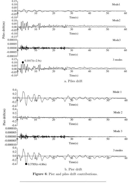
It can be seen that tmax is 2.9 s for maximum piles drift and 4.86 s for maximum pier drift.
( )
n
D t for these instants are shown in Table 3. It can also be seen that target interstory drift of piles and pier are 0.1017m and 0.3785m respectively.
a. Piles drift
b. Pier drift
Figure 6: Pier and piles drift contributions.
max t
1( )
D t D t2( ) D t3( )
2.9 0.11875 0.09999 0.00175 4.86 -0.28672 0.04182 -0.00430
Table 3: Ground Motion Ensemble.
0 10 20 30 40 50 60
-0.10 -0.05 0.00 0.05 0.10 0.15
0 10 20 30 40 50 60
-0.15 -0.10 -0.05 0.00 0.05 0.10
0 10 20 30 40 50 60
-0.00010 -0.00005 0.00000 0.00005 0.00010
0 10 20 30 40 50 60
-0.10 -0.05 0.00 0.05 0.10 0.15 Mode1 Time(s) Mode2 Pil es dr if t( m ) Time(s) Mode3 Time(s) 3 modes Time(s) 0.1017(t=2.9s)
0 10 20 30 40 50 60
-0.4 -0.2 0.0 0.2 0.4
0 10 20 30 40 50 60
-0.4 -0.2 0.0 0.2 0.4
0 10 20 30 40 50 60
-0.000010 -0.000005 0.000000 0.000005 0.000010
0 10 20 30 40 50 60
Latin American Journal of Solids and Structures 11 (2014) 2696-2712
General force vectors are computed from Eq. (4) and shown in Figure 7. General force vectors that computed from GPA are also shown in Figure 7. It turns out that they are consistent with each other. 0 5 10 15 20 25 30 35
-20 -15 -10 -5 0 5 10 15 20
GPA MGPA
Lateral force vectors
Superstructure mass Cap mass He ig ht (m) Node 41 0 5 10 15 20 25 30 35
-6 -4 -2 0 2
GPA MGPA Hei ght (m ) Superstructure mass Node 41 Cap mass
a. Piles b. Pier
Figure 7: Lateral force vectors of pier and piles.
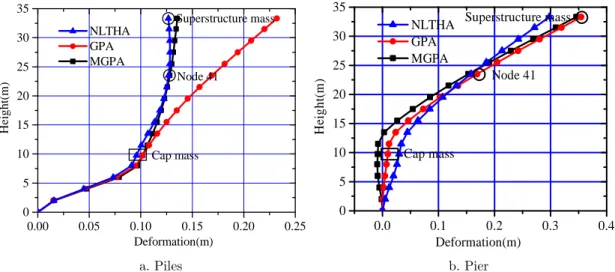
The simplified bridge model are pushed with the lateral force vectors to corresponding target interstory drifts. Deformation shapes of the model are shown in Figure 8. When interstory drifts of pier and piles are maximum in nonlinear time history analysis (NLTHA), deformation shapes of the model are recorded and shown in Figure 8 too.
0 5 10 15 20 25 30 35
0.00 0.05 0.10 0.15 0.20 0.25
NLTHA GPA MGPA Deformation(m) Superstructure mass Cap mass H e ight (m
) Node 41
0 5 10 15 20 25 30 35
0.0 0.1 0.2 0.3 0.4
Deformation(m) NLTHA GPA MGPA H ei ght (m ) Superstructure mass Node 41 Cap mass
a. Piles b. Pier
Figure 8: Deformation shapes of pier and piles.
Latin American Journal of Solids and Structures 11 (2014) 2696-2712 3.4 Validation of Modified GPA Procedure
Modified GPA, MPA and IDA of the elevated pile foundation system are conducted due to an ensemble of 9 ground motion records. The records are scaled with PGAs ranging from 0.1g to 0.6g. Contributions of the first three modes are considered. Inelastic contributions of the first two modes are considered. Responses of the modified GPA and MPA of the simplified model are com-pared with each other, as well as the benchmark responses derived from IDA.
Maximum moments of pier and piles
Figure 9 shows the maximum moments of pier and piles computed by modified GPA, MPA and IDA with scaled accelerations (PGA range from 0.1g to 0.6g).
When the elevated pile foundation system vibrates in linear elastic or early inelastic range, the moments predicted by modified GPA for pier are well consonant with the IDA results and the moments predicted by MPA are a little conservative under the ground motions Cape, El, Erzin-can, Kern, Kobe, Loma and Sylmar. In further inelastic range, the moments predicted by the MPA for pier are well consonant with the IDA results.
The moments predicted by modified GPA and MPA for piles are almost the same as each other. They match the IDA results well in both linear elastic range and inelastic range.
Plastic hinge rotations of pier and piles
Plastic hinge rotations of pier and piles are illustrated in Figure 10 with scaled accelerations (PGA range from 0.1g to 0.6g). Except for plastic hinge rotations in ground motions of Kobe and Moorpark, reasonable plastic rotations are predicted by modified GPA. Most of them are more accurate than the plastic hinge rotations predicted by MPA. It is revealed that modified GPA provides better seismic evaluation of plastic hinge rotations than MPA.
Modified GPA is able to track the formation of plastic hinges, while MPA is not. For example, when the elevated pile foundation system is subjected to the scaled Bigbear (0.5g and 0.6g), El (0.3g), Kobe (0.4g) and Sylmar (0.3g), the plastic hinge formed in the pier is not captured by MPA, but it is successfully captured by modified GPA.
4 SUMMARY AND CONCLUSIONS
Based on the GPA procedure, modified GPA is proposed for seismic performance evaluation of bridges with elevated pile foundation systems. Principle and basic steps of the modified GPA are developed at first. Then, a bridge with elevated pile foundation systems was chosen for case study. The necessity of considering inelastic contributions of the second mode in multi-mode pushover analysis is illustrated. Modified GPA, MPA and IDA of the simplified model of the bridge are conducted. At last, maximum moments and plastic rotations of the system computed by the three methods are compared with each other. Main conclusions of this study are summa-rized as following:
Latin American Journal of Solids and Structures 11 (2014) 2696-2712
2. Modified GPA can be applied successfully for seismic performance evaluation of the bridge. Inelastic contributions of the second mode can be conveniently considered by Modified GPA.
Latin American Journal of Solids and Structures 11 (2014) 2696-2712 Figure 10: Rotations of the pier and piles.
Latin American Journal of Solids and Structures 11 (2014) 2696-2712
piers of bridges are usually designed as capacity-protected components, they vibrate primarily in linear elastic or early inelastic range. In this respect, modified GPA is more attractive for longi-tudinal seismic performance evaluation of bridges with elevated pile foundation systems.
4. Compared with MPA results, most of plastic hinge rotations predicted by modified GPA are closer to IDA results. Locations of plastic hinges are predicted precisely by Modified GPA, while some locations are not captured by MPA.
5. It should be noted that MGPA procedure is proposed for pushover analyses of bridges with elevated pile foundation systems in longitudinal direction, in which the effective SDOF system of second-mode also enters inelastic range. Basically, MGPA can also applied to bridges or struc-tures in which higher modes don’t enter inelastic range.
Limitations
Since MGPA uses the UMRHA method to calculate generalized pushover parameters, its accu-racy is better when a structure vibrates in early inelastic range. When a structure enters heavy inelastic range, accuracy of MGPA results should be used with caution, and NL-THA may be used.
Acknowledgements
This research is supported by the Ministry of Science and Technology of China under Grant No. SLDRCE09-B-08, Kwang-Hua Fund for College of Civil Engineering, Tongji University, and by the National Natural Science Foundation of China under Grants No.51278376, No.50978194 and No.90915011. Their supports are gratefully acknowledged.
References
Akhaveissy, A.H., (2012). Finite element nonlinear analysis of high-rise unreinforced masonry building. Latin American Journal of Solids and Structures 9: 547-67.
Antoniou, S., Pinho, R., (2004). Advantages and limitations of adaptive and non-adaptive force-based pushover procedures. Journal of Earthquake Engineering 8: 497-522.
Antoniou, S., Pinho, R., (2004) Development and verification of a displacement-based adaptive pushover proce-dure. Journal of Earthquake Engineering 8: 643-661.
Applied Technology Council. Improvement of nonlinear static seismic analysis procedures. Redwood City, Califor-nia: Applied Technology Council; 2005.
Chen, Y., (1997). Assessment on pile effective lengths and their effects on design .1. Assessment. Computers & Structures 62: 265-286.
Chopra, A.K., (2007). Dynamics of Structures: Theory and Applications to Earthquake Engineering. Upper Saddle River, New Jersey: Pearson Prentice Hall.
Chopra, A.K., Goel, R., (2001). A modal pushover analysis procedure to estimate seismic demands on buildings: Theory and preliminary evaluation. University of California, Berkeley, California: Pacific Earthquake Engineering Research Center.
Chopra, A.K., Goel, R.K., (2002). A modal pushover analysis procedure for estimating seismic demands for build-ings. Earthquake Engineering & Structural Dynamics 31: 561-582.
Latin American Journal of Solids and Structures 11 (2014) 2696-2712
Elnashai, A.S., (2001). Advanced inelastic static (pushover) analysis for earthquake applications. Structural Engi-neering and Mechanics 12: 51-69.
Forcael, E., Gonzalez, V., Orozco, F., Opazo, A., Belmar, C., Vera, J., (2014). Study of Structural Capacity and Serviceability affecting the obstruction of Residential Door. Latin American Journal of Solids and Structures 11: 410-436.
Gupta, B., Kunnath, S.K., (2000). Adaptive spectra-based pushover procedure for seismic evaluation of structures. Earthquake Spectra 16.
Kalkan, E., Kunnath, S.K., (2006). Adaptive modal combination procedure for nonlinear static analysis of build-ing structures. Journal of Structural Engineerbuild-ing-Asce 132: 1721-1731.
Kim, D., Chaudhary, S., Nocete, C.F., Wang, F., Lee, D.H., (2011). A probabilistic capacity spectrum strategy for the reliability analysis of bridge pile shafts considering soil structure interaction. Latin American Journal of Solids and Structures 8: 291-303.
Krawinkler, H., (1996) Pushover analysis: why, how, when, and when not to use it. Proceedings of the 65th An-nual Convention of the Structural Engineers Association of California.
Krawinkler, H., Seneviratna, G.D.P.K., (1998). Pros and cons of a pushover analysis of seismic performance eval-uation. Engineering Structures 20: 452-464.
Mazzoni, S., McKenna, F., Scott, M.H., Fenves, G.L., (2007). Open system for earthquake engineering simulation (Opensees) user command-language manual. University of California, Berkeley, California: Pacific Earthquake Engineering Research Center.
Papanikolaou, V.K., Elnashai, A.S., (2005). Evaluation of conventional and adaptive pushover analysis I: Meth-odology. Journal of Earthquake Engineering 9: 923-941.
Paraskeva, T.S., Kappos, A.J., Sextos, A.G., (2006). Extension of modal pushover analysis to seismic assessment of bridges. Earthquake Engineering & Structural Dynamics 35: 1269-1293.
Sucuoglu, H., Gunay, M.S., (2011). Generalized force vectors for multi-mode pushover analysis. Earthquake Engi-neering & Structural Dynamics 40: 55-74.
Vamvatsikos, D., Cornell, C.A., (2002). Incremental dynamic analysis. Earthquake Engineering & Structural Dynamics 31: 491-514.
Wancheng, Y., Jun, Y., (2008). Lateral Load Pattern Study of Pushover Analysis for Elevated Pile Foundation System of Bridges. Journal of Tongji University 36.