Abstract— This paper evaluates several signal processing
techniques for optical dual-polarization quadrature phase-shift keying (DP-QPSK) coherent receivers, using offline post-processing of experimental data. In addition to electronically separating the two polarization multiplexed signals, the investigated signal processing algorithms also compensate for chromatic dispersion (CD) and polarization mode dispersion (PMD). In particular, we investigate two distinct architectures:
1) Constant modulus algorithm (CMA) equalization followed by feedforward phase recovery.
2) Decision-directed least mean square (DD-LMS) equalization combined with decision-directed phase recovery.
The interplay of both architectures with bulk dispersion compensators and carrier recovery algorithms is also analyzed.
Index Terms—Blind equalization, coherent receiver, optical communications, polarizations demultiplexing.
I. INTRODUCTION
The increasing demand for data traffic in optical networks has been pushing the development of
spectrally-efficient systems using polarization multiplexing and multilevel modulation formats. In this
context, dual-polarization quadrature phase-shift keying (DP-QPSK) transmission emerged as an
attractive alternative. Such systems convey four bits per symbol (considering both polarization
orientations), consequently reducing the symbol rate by the same factor in comparison to a binary
system at the same bit rate. In addition to relaxing hardware requirements, the reduced symbol rate
also accounts for an increased tolerance to inter-symbol interference (ISI). If coherently detected,
polarization multiplexed QPSK signals can be separated at the receiver by signal processing
algorithms, and linear effects, such as chromatic dispersion (CD) and polarization mode dispersion
(PMD), can be compensated for standard equalization techniques. Indeed, DP-QPSK with coherent
detection has been considered a viable alternative for future 100 GbE transmission (at a data rate of
112 Gb/s, or 28 Gbaud). While real-time 100 GbE transceivers are not yet commercially available,
research on the signal processing algorithms for the receiver has been relying on the offline
post-processing of experimentally captured data, using fast oscilloscopes.
1 now with ADVA optical networking.
Analysis of Signal Processing Techniques for
Optical 112 Gb/s DP-QPSK Receivers with
Experimental Data
Thiago F. Portela, Diego V. Souto, Valery N. Rozental, Hugo B. Ferreira, Darli A. A. Mello OCNLab, Department of Electrical Engineering, University of Brasilia
This paper evaluates several signal processing techniques for optical dual-polarization quadrature
phase-shift keying (DP-QPSK) coherent receivers, using offline post-processing. In particular, we
investigate two distinct architectures: constant modulus algorithm (CMA) equalization followed by
feedforward phase recovery; and decision-directed least mean square algorithm (DD-LMS)
equalization combined with decision-directed phase recovery. The interplay of both architectures with
bulk dispersion compensators and frequency recovery algorithms is also analyzed. The paper is
structured as follows: Section 2 describes the signal processing algorithms investigated in the paper;
Section 3 presents the experimental results obtained by offline post-processing; lastly, Section 4
concludes the paper.
II. SIGNAL PROCESSING ALGORITHMS
A. Resampling, Normalization and Orthogonalization
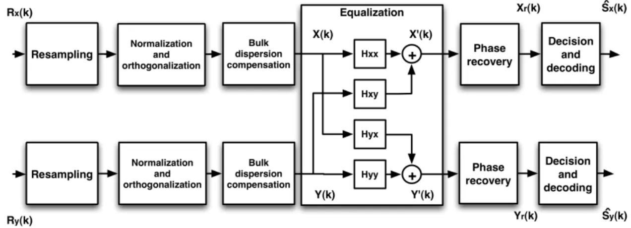
Figure 1 shows the canonic chain of signal processing algorithms commonly employed in
DP-QPSK receivers. The first block is an experimental artifice used to adapt the sampling rate of fast
oscilloscopes to the data rate of the consecutive signal processing algorithms. The subsequent
orthogonalization and normalization block counteracts eventual quadrature imbalances generated at
the receiver front-end [1], and is followed by bulk dispersion compensators. Residual CD and PMD
are then compensated in the butterfly adaptive equalizer. Lastly, phase noise effects are mitigated in
the phase recovery module. An additional frequency recovery algorithm may be placed in several
positions, and therefore was omitted from the figure.
Fig. 1. Chain of signal processing algorithms for a coherent DP-QPSK receiver.
In this work, the system operates at 28 Gbaud, and data is sampled at 50 GSamples/s. Since
equalization is accomplished by /2-spaced equalizers, the input data is resampled at a 56/50 rate.
B. Bulk Dispersion Compensation
Dispersion compensation in optical coherent receivers may be carried out by separate blocks: a bulk
equalizer with fix coefficients that compensates for most of the CD accumulated on the link, and an
adaptive equalizer that compensates for any residual dispersion. In particular, the time-domain
an interesting alternative given the flat amplitude response of the CD transfer function. The
coefficients of the resulting finite impulse response (FIR) filter are given by:
= − , (1)
− 2 ≤ ≤ 2 and = 2 | |
2 ! + 1, (2)
where is the fiber dispersion coefficient, is the operating wavelength, is the propagation
distance, is the speed of light, and is the sampling time.
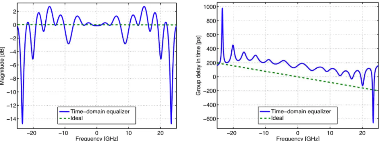
Figures 2 and 3 show the amplitude and phase responses of the time-domain compensator for =
17 ps/[nm · km], z = 50 km, and T = 1/(56 · 109)s (corresponding to the total accumulated dispersion
of the experimental setup). Although the amplitude response is relatively flat in the central part of the
filter, the ripple around 15 GHz may amplify noise components. As for the phase response, the group
delay in the main portion of the filter exhibits a satisfactory agreement with the ideal curve.
Fig. 2. Bulk dispersion compensating filters. Amplitude response.
Fig. 3. Bulk dispersion compensating filters. Phase response.
C. Butterfly Equalizer and Phase Recovery
The adaptive butterfly equalizer separates the two polarization multiplexed signals and compensates
for linear fiber effects such as PMD and residual CD that is left over from the bulk compensator.
The M-taps FIR filters &'', &(', &'( and &(( may be updated according to a stochastic gradient
algorithm [2], [3]:
&'' → &''+ *+',( )/,
&('→ &('+ *+'0( )/,
&'(→ &'(+ *+(,( )/,
&(( → &((+ *+(0( )/,
where * is the step-size, +'( ) and +(( ) are the error signals that drive the equalization process.
The equalizer outputs 27( ) and 67( ) are obtained as:
27( ) = &
'',( ) + &('0( ), (3)
67( ) = &'(,( ) + &((0( ). (4)
The next sections particularize the error signal for the butterfly equalizers.
D. System 1
This system uses the constant-modulus algorithm (CMA) for signal equalization, so the error signal
is computed as:
+'( + 1) = (1 − |27( )| )27( ), (5)
+(( + 1) = (1 − |67( )| )67( ). (6)
Since the CMA attempts to minimize variations of |27( )| and |67( )| with respect to a constant
value [4], [5], the equalization process is immune to phase-noise or frequency offsets. Accordingly,
phase noise may be subsequently mitigated by the Viterbi & Viterbi feedforward phase recovery
algorithm, as depicted in Fig. 4.
Fig. 4. The Viterbi & Viterbi phase recovery algorithm.
The first step of the algorithm is to remove the data dependency by raising the complex signal to the
fourth power. Afterwards, the sequence is filtered in order to minimize the influence of additive noise
in the estimation process [6], and the signal argument is divided by four. The resulting argument
sequence is then submitted to a phase unwrapper (PU) [7], to allow the resulting phase to vary
between −∞ to +∞, instead of being limited between −: and +:. Note that the filters corresponding
to the “2” and “6” outputs are updated independently, so singularities may occur (the same input
being produced in both outputs). Several singularity-avoidance techniques have been recently
proposed, exhibiting no penalty when compared to the standard CMA [8]. In this paper, we limited
ourselves to verifying that the standard CMA equalizer converged to a singularity-free solution.
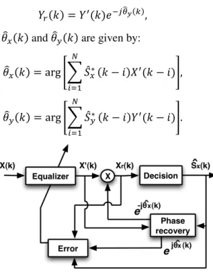
E. System 2
This system is based on a CMA startup followed by the decision-directed least mean square
algorithm (DD-LMS) filter tracking, as shown in Fig. 5. The DD-LMS filter updating rule is given by
[3]:
+'( + 1) = ;<=( )>?@'( ) − 2A( )B, (7)
+(( + 1) = ;<C( )>?@(( ) − 6A( )B, (8)
where ?@'( ) and ?@(( ) are the resulting symbols after minimum distance decision. Note in this case
2A( ) = 27( ) D ;<=( ), (9)
6A( ) = 67( ) D ;<C( ), (10)
where the estimated phases EF'( ) and EF(( ) are given by:
EF'( ) = arg JK ?@'∗ M
NOP
( − Q)27( − Q)R,
(11)
EF(( ) = arg JK ?@(∗ M
NOP
( − Q)67( − Q)R.
(12)
Fig. 5. DD-LMS equalization for the X signal.
F. Frequency Recovery
Frequency recovery algorithms compensate for a possible frequency offset between transmitter and
local oscillator lasers. Once this frequency offset ∆T is estimated, frequency recovery may be easily
implemented by multiplying the equalized symbols 27( ) by the accumulated phase-shift U?( ) =
D ∆V W = U?(1) , where is the symbol period. In this paper, we analyze two frequency
recovery algorithms:
• The phase-difference algorithm estimates the phase-shift U?(1) from the equalized samples 27( )
and 67( ):
U?X(1) ≈ 14 arg J1K 27∗ M
NOP
(Q): 27(Q − 1):R,
(13)
where [ is the number of samples used in the estimation process.
• The FFT algorithm estimates ∆T as the maximum value of the Fourier transform modulus of the equalized sequence raised to the fourth power:
∆TX ≈ maxV [|^^ (2
7:)|]
4 . (14)
III. EXPERIMENTAL RESULTS FROM OFFLINE POST-PROCESSING
Figure 6 shows the experimental setup for the 112 Gb/s DP-QPSK system. At the transmitter, a
pseudorandom binary sequence (PRBS) is generated at 28 Gb/s. The original sequence drives the
version drives the quadrature co
by a pulse carver. Lastly, the p
signal into two orthogonal pol
decorrelating the vertical and h
(PMF), and recombining the two
The receiver is composed of th
a high performance oscilloscope
post-processing. All investigated
values were obtained by compa
initial 10,000 training symbols w
(a) OSNR = 17 dB
(d) OSNR = 20 dB
Fig. 7. Constellations of the receive (10,000 symbols). The circle-like u orientations.
component. The resulting optical signal is subsequ
polarization multiplexed signal is generated by
olarization orientations (using a polarization be
horizontal components by a 2 meters polarizatio
o components in a polarization beam combiner (PB
Fig. 6. Experimental setup.
the traditional polarization diversity front-end arch
pe, at 50 Gsamples/s, which stores the sampled
ed cases used the single-spike initialization for the
paring the decoded sequence with 550,000 transm
were not used for BER computation.
(b) OSNR = 18 dB (c) O
(e) OSNR = 21 dB (f) O
ved and CMA-demultiplexed signals for the investigated OS upper curves indicate a strong mixture of the vertical and
quently RZ-modulated
splitting the optical
beam splitter (PBS)),
tion maintaining fiber
(PBC).
rchitecture followed by
sequence for offline
butterflyfilters. BER
smitted symbols. The
OSNR = 19 dB
) OSNR = 22 dB
The first investigated scenario consists of a fiber-free setup with a noise-loading amplifier. In Fig.
7, the circle-like constellations of the received signals after normalization indicate a strong mixture of
the vertical and horizontal polarization orientations for the investigated OSNRs (at 0.1 nm). We
analyze the performance of the two frequency recovery algorithms.
Figure 8 shows the estimated frequency offset ∆T as a function of the system OSNR, computed
using all 2′ and 6′ samples obtained after the training phase. Since the frequency offset is in the order
of some few dozens of MHz, its measurement would require very high resolution optical spectral
analyzers. Alternatively, we analyze the dispersion of the four estimated values: the phase-difference
algorithm using 2′ and 6′, and the FFT algorithm using 2′ and 6′. At high OSNR, the estimates
produced by the two algorithms coincide, however, as the OSNR decreases, the estimates of the
phase-difference algorithm diverge. This indicates that, although the phase-difference algorithm is
less computationally complex, it is also more susceptible to additive noise.
Fig. 8. Performance of the phase-difference and FFT frequency recovery algorithms.
Figure 9 shows the BER versus OSNR curves for the two investigated systems (CMA or DD-LMS
filter tracking) for the butterfly equalizer with 5 T/2-spaced taps and frequency recovery using the
phase-difference algorithm. Both systems achieved error-free transmission for OSNR values higher
than 22 dB, and the CMA exhibited a slightly lower BER than the DD-LMS algorithm for low OSNR
values. This may be explained by the fact that the DD-LMS algorithm depends on correct decisions,
and symbol errors degrade the overall DD equalizer performance.
In general CMA equalization is preferred because of its immunity to phase noise and residual
frequency offset. The performance of the equalization process, for a given residual frequency offset
(in OSNR of 19 dB), can be observed in Fig. 10. Even though CMA has the advantage of being
immune to the residual frequency offset, the carrier recovery process is still affected. As expected, the
DD-LMS algorithm exhibited a lower tolerance to the residual frequency offset, because the
Fig. 9. Performance curves for the CMA and DD-LMS systems under amplified spontaneous emission noise.
Fig. 10. Performance curves for the CMA and DD-LMS systems under amplified spontaneous emission noise and residual frequency offset.
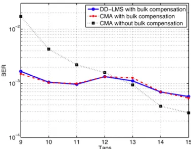
In the second investigated scenario, we post-processed signals impaired by residual chromatic
dispersion (850 ps/nm) and polarization mode dispersion (50 ps DGD), at OSNR = 18 dB. Figure 11
shows the BER as a function of the number of adaptive filter taps. The dot-dashed and solid curves
correspond to the CMA and DD-LMS equalizers, respectively, when the bulk dispersion
compensating filter is designed for 850 ps/nm. The performance of the fully-adaptive CMA equalizer
is indicated by the dotted line. The fully-adaptive DD-LMS algorithm, in turn, exhibited an
unsatisfactory performance, and was therefore omitted from the diagram. Clearly, the bulk dispersion
compensator allowed to reduce the required number of adaptive filter taps, however, a minimum
number of filter taps was still needed to equalize the PMD. Note that the fully-adaptive CMA
equalizer achieved the lowest BER values after 13 taps. This inferior performance of the investigated
Fig. 11. Performance curves for Systems 1 and 2 under amplified spontaneous emission noise, first-order PMD (DGD = 50 ps) and residual CD = 850 ps/nm.
IV. CONCLUSION
We analyzed the performance of several signal processing algorithms for optical DP-QPSK 112
Gb/s coherent receivers using the offline post-processing of experimental data. In particular, two
systems based on CMA and DD-LMS equalization were investigated. Both systems performed
similarly in the separation of polarization multiplexed data, provided that a possible frequency offset
between transmitter and local oscillator lasers was properly compensated. Two frequency recovery
algorithms were compared, and the FFT-based alternative exhibited a higher tolerance to additive
noise, though being more computationally complex. We also investigated the performance of the two
equalization strategies combined with bulk dispersion compensators, in the presence of chromatic
dispersion and the first order polarization mode dispersion (DGD). The results indicated that
time-domain equalizer in some cases impairs the BER due to ripple in its amplitude response, which may
account for some noise amplification.
ACKNOWLEDGMENT
This work was supported by the Innovation Center, Ericsson Telecomunicações S.A., Brazil.
REFERENCES
[1] Fatadin, S. Savory, and D. Ives, “Compensation of quadrature imbalance in an optical QPSK coherent receiver,” Photonics Technology Letters, IEEE, vol. 20, no. 20, pp. 1733 –1735, oct.15, 2008.
[2] S. J. Savory, “Digital filters for coherent optical receivers,” Opt. Express, vol. 16, no. 2, pp. 804–817, 2008. [Online]. Available: http://www.opticsexpress.org/abstract.cfm?URI=oe-16-2-804
[3] S. J. Savory, G. Gavioli, R. I. Killey, and P. Bayvel, “Electronic compensation of chromatic dispersion using a digital coherent receiver,” Opt. Express, vol. 15, no. 5, pp. 2120–2126, 2007. [Online]. Available:
http://www.opticsexpress.org/abstract.cfm?URI=oe-15-5-2120
[5] J. Johnson, R., P. Schniter, T. Endres, J. Behm, D. Brown, and R. Casas, “Blind equalization using the constant modulus criterion: a review,” Proceedings of the IEEE, vol. 86, no. 10, pp. 1927–1950, Oct 1998.
[6] F. A. Garcia, D. A. Mello, and H. Waldman, “Feedforward carrier recovery for polarization demultiplexed signals with unequal signal to noise ratios,” Opt. Express, vol. 17, no. 10, pp. 7958–7969, 2009. [Online]. Available:
http://www.opticsexpress.org/abstract.cfm?URI=oe-17-10-7958
[7] E. Ip, J. M. Kahn, “Feedforward carrier recovery for coherent optical communications,” J. Lightwave Technol., vol. 25, pp. 2675–2692, 2007.