Abstract— This paper presents a qualitative analysis of the impact caused by fiber propagation effects and by a cascade of optical filters, designed for 10 Gb/s NRZ OOK transmission, and optical amplifiers on a 20 Gb/s NRZ OOK optical signal traveling a 390 km fiber link. The choice for such bit rate and modulation format has been driven by the 50 GHz bandwidth of the filters (in the ITU DWDM grid) and by simplicity and low cost, respectively. The system, investigated experimentally and numerically, comprises 4 spans of standard fiber and a concatenation of 7 dispersion compensating modules, 4 wavelength selective switch reconfigurable optical add and drop multiplexers, 9 erbium-doped fiber amplifiers and 1 WDM-DEMUX (> 75 GHz bandwidth). We demonstrate the feasibility of such bit rate upgrade in a cost-effective network planning strategy, which may be more adequate for regions where the demand for bandwidth do not require a jump to higher capacities (i.e. 40 and 100 Gb/s), thus allowing for reusing the 10 Gb/s installed infrastructure.
Index Terms— Amplified spontaneous emission accumulation, fiber propagation effects, dispersion compensating module, nreturn-to-zero on-off key 20 Gb/s, spectral narrowing, wavelength selective switch reconfigurable optical add and drop multiplexer.
I. INTRODUCTION
Nowadays, the majority of optical networks in operation have been designed and optimized for
transmission of 10 Gb/s Non-Return to Zero (NRZ) ON-OFF Keying (OOK) in a Dense Wavelength
Division Multiplexing (DWDM) system. As the Internet traffic increases, higher bit rates are required
for supporting the bandwidth demand, which leads to the recursive problem of fulfilling the capacity
requirements with a minimum capital expense [1]. In this scenario, a key design driver is that the new
systems must ideally integrate with the existing ones without requiring significant changes to the
installed equipment. Many technologies have been considered for the next bit rate hierarchies, i.e.
40 Gb/s, 100 Gb/s and beyond, most of them based on phase modulation techniques and coherent
Transmission of a 20 Gb/s NRZ OOK Signal
Throughout a 390 km Fiber Link
and a Cascade of 11 x 50 GHz Filters
and 9 x EDFAs
Daniel M. Pataca, Julio C. R. F. Oliveira, Antonio A. Juriollo, Adolfo F. Herbster
Fundação Centro de Pesquisa e Desenvolvimento em Telecomunicações, CPqDCampinas, Brazil; {pataca; julioc; amauri; adolfo}@cpqd.com.br.
Mônica de Lacerda Rocha
detection, which present higher spectral efficiency and may be less affected by linear regime physical
impairments [2], [3]. However, phase modulation and coherent detection not necessarily lead to
higher spectral efficiency. This happens only if such modulation techniques are associated with
multi-level signaling. Such higher bit rates imply that the emerging technologies must support a wide
bandwidth signal [2]. Under such spectral constrain, the low cost requirement is not well
accomplished since part of the network legacy may not be used, added to the fact that those solutions
are expensive and technically complex [4].
Considering propagation in linear regime, some of critical parameters to overcome are chromatic
dispersion, Polarization Mode Dispersion (PMD), spectral narrowing, caused by filter concatenation,
and accumulated Amplified Spontaneous Emission (ASE) noise. Transmission through a cascade of
optical filters, such as Dispersion Compensation Modules (DCMs), based on chirped fiber Bragg
gratings, and Reconfigurable Optical Add and Drop Multiplexers (ROADMs) is common place in
Metro and Long-Haul networks. Particularly for 40 Gb/s, it may be a more severe impairment than for
100 Gb/s, where the modulated signal results from the multiplexing of 4 x 25 Gb/s streams, as
recommended by the Optical Internetworking Forum (OIF) for coherent Dual Polarization Quadrature
Phase Shift Keying (DP QPSK) [5]. Furthermore, despite the advantages provided by the new formats
and technologies, traffic demands across the network may not require 40 and 100 Gb/s capacity
everywhere. So, a cost-effective network design needs to exploit the scenario of operation with Mixed
Line Rates (MLRs) [1], [6].
In that approach, we have investigated the possibility of implementing an intermediate upgrade in
an existing 10 Gb/s infrastructure without much expenses, by using NRZ OOK, direct detection and
low loss optical dispersion compensator, i.e. 10 Gb/s-designed DCM based on chirped gratings, thus
allowing for propagation in linear regime. We then analyze the effect of a large concatenation of filter
and ASE across a nearly 400 km long optical path traversed by a 20 Gb/s NRZ OOK signal. That bit
rate has been chosen due to the 50 GHz bandwidth of each filter, which does not allow the
transmission of a 40 Gb/s NRZ OOK signal. We have carried out experimental and numerical
measurements for evaluating the transmission performance.
The paper is organized as follows. Section II presents the implications of optical filters
concatenation, Section III describes the experimental setup and the numerical simulation parameters.
Section IV presents the results and discussion and, in Section V, the conclusions are described.
II. CASCADE OF OPTICAL FILTERS
In a WDM optical network, a signal can be filtered several times from its origin to its destination.
That filtering comes from the signal passage, for example, through ROADMs, DCMs and Optical
Cross-Connects (OXCs), which may be installed along the optical path. Those filters exhibit nonideal
response, tilt and ripple. Moreover, the phase transfer function can not vary linearly with frequency.
Those effects are magnified by increasing the concatenation of devices, thus causing spectral clipping
of the signal spectrum and/or dispersion problems due to nonlinearities of the phase response, which
can limit the maximum link length [7], [8].
The spectral clipping and dispersion of the filter can lead to the signal distortion in the time domain,
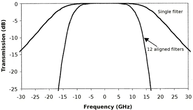
causing a Q-factor penalty. The effective spectral transfer function of a cascade of filters results from
the multiplication of all filter responses and, generally, is much narrower than that due to a single
filter. Figure 1 shows the effective transfer functions of a single optical filter with 36 GHz bandwidth
and 12 cascaded and aligned filters, obtained with the Optiwave Systems Inc. OptiSystem 9.0
software tool. As expected, it can be noticed that the effective filter function after 12 filters is much
narrower than after a single filter.
Fig. 1. Effective transfer functions of a single optical filter and 12 aligned filters.
The optical impairment penalty associated with filter concatenation effects is define as an
eye-closure penalty (ECP). For a thermal noise-limited system, the eye-eye-closure penalty may be further
translated into a Q-factor penalty. The ECP calculation considering only contributions to the eye
closure from signal distortion can be obtained as:
(
)
(
)
− − = ave BB ave BB BB I I I I I I ECP max , 0 min , 1 , max, , 0 min, , 1 log 20 (1)where the numerator represents the eye opening in the back-to-back condition and the denominator
represents the eye opening under the fiber transmission conditions [9]. Note that the ECP in decibel is
defined in the 20 log ( ) format, here, but may be estimated in the 10 log ( ) format in case the
value of level ‘1’, in the back-to-back and fiber transmission configurations, respectively. Similarly,
I0,max,BBand I0,max, to the maximum value of level ‘0’, in the back-to-back and fiber transmission
configurations, respectively and, finally, Iave,BB and Iave correspond to the eye-diagram average
intensity in the back-to-back and fiber transmission configurations, respectively.
III. SETUP
A. Experiment
Figure 2 shows the experimental setup. The pilot signal, generated by a CW external cavity laser,
operates in a constant power mode and is tuned into λ = 1544.53 nm, channel 41 of ITU DWDM grid.
The laser output is connected to a lithium niobate Mack-Zehnder modulator, designed for 40 Gb/s
through a polarization controller, which provides the modulator extinction ratio optimization. External
20 Gb/s RF signal, coming from a NRZ 231 – 1 Pseudo-Random Bit Sequence (PRBS), and amplified
by a broadband (40 GHz) amplifier, is injected into the RF input of the modulator. Four WSS-based
ROADM units, designed and developed at CPqD, Brazil, are placed, each one in-between two
erbium-doped fiber amplifiers, where the first one operates as an insertion loss compensator
(pre-amplifier) and the second boosts the signal at each span input. Four singlemode standard fiber (G.652)
links complete the propagation medium (3 x 100 km and 90 km), leading to a total of 390 km
transmission length.
Seven DCMs with fixed and tunable dispersion, based on chirped fiber Bragg gratings, are placed at
the output of the spans, according to the following scheme: DCM1 comprises one fixed dispersion
module (for 80 km, i.e. -1340 ps/nm), which means that a residual dispersion is added into the second
span; DCM2 corresponds to the combination of one fixed (80 km, -1340 ps/nm) and one tunable (set
to 550 ps/nm) compensator; DCM3, two fixed modules (60 km, 1005 ps/nm, and 40 km,
-670 ps/nm); DCM3, two fixed (60 km, -1005 ps/nm, and 40 km, --670 ps/nm); DCM4, one fixed
(60 km, -1005 ps/nm) and one tunable (set to -350 ps/nm). At the link end, another pre-amplifier is
used to improve the receiver sensitivity, furthermore, an extra WDM-DEMUX (>75 GHz bandwidth)
is used to select the transmitted channel (Ch 41) and also to filter the ASE coming from that EDFA.
For performance monitoring, we use a wideband scope, synchronized by a clock recover equipment
and an Optical Spectrum Analyzer (OSA). For visualizing the eye diagrams, from which we
qualitatively evaluate the transmission performance throughout the line, we use a plug-in converter,
which provides singlemode optical channel unfiltered Bandwidth (BW) of 40 GHz, with optical
transition time (= 0.48 x BW-1) of 12 ps at Full Width Half Maximum (FWHM) and 65 W of
characteristic RMS noise. For the electrical side, this module provides 50 GHz BW, less than 13.2 ps
of transition time (=0.35 x BW-1) and 0.60 mV of characteristic RMS noise. Note that the high
electrical bandwidth of the photodiode is expected to produce, as a drawback, a large amount of
the dynamic range of the link, in our setup the front end is protected by an optical monitor/attenuator,
which limits the maximum optical power incident on it.
Fig. 2. Experimental setup. Pn, WSSn and Bn stand for the n-th Pre-amplifer, Wavelength Selective Switch and Booster amplifier, respectively. G.652 refers to the ITU recommendation relative to the standard singlemode fiber.
DCM stands for Dispersion Compensating Module.
B. Simulation
We used the same experimental diagram in the OptiSystem 9.0 simulator, that solves the nonlinear
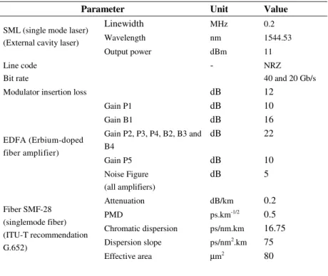
Schrödinger equation, configured with the parameters indicated in Table 1. Some parameters, such as
TABLE I.SIMULATION PARAMETERS (SAME USED IN THE EXPERIMENTAL SETUP)
Parameter Unit Value
SML (single mode laser) (External cavity laser)
Linewidth MHz 0.2
Wavelength nm 1544.53
Output power dBm 11
Line code Bit rate
- NRZ
40 and 20 Gb/s
Modulator insertion loss dB 12
EDFA (Erbium-doped fiber amplifier)
Gain P1 dB 10
Gain B1 dB 16
Gain P2, P3, P4, B2, B3 and B4
dB 22
Gain P5 dB 10
Noise Figure (all amplifiers)
dB 5
Fiber SMF-28 (singlemode fiber) (ITU-T recommendation G.652)
Attenuation dB/km 0.2
PMD ps.km-1/2 0.5
Chromatic dispersion ps/nm.km 16.75
Dispersion slope ps/nm2.km 75
Effective area µm2 80
IV. RESULTS AND DISCUSSION
In order to evaluate the physical impairments on a 40 Gb/s NRZ OOK signal, we simulated its
transmission on the setup seen in Figure 2. The eye diagrams, presented in Figure 3, confirm the
strong limitation imposed by the impairments on that bit rate and modulation format propagation.
The eye diagram degradation is a consequence of many effects in mutual combination, but by
observing the spectral narrowing due to the cascade of filters (WSSs, DCMs and DEMUX) 3 along
the optical path, as indicated in Figure 4, it is possible to infer how strongly the narrow spectral
window might penalize the system performance. This fact, alone, implies that for such system
configuration, the transmission of 40 Gb/s NRZ OOK is not feasible, despite of other problems
associated to other physical impairments. From those indications, and considering the aim of reusing a
10 Gb/s infrastructure, we have chosen 20 Gb/s NRZ OOK as the basis for our investigations.
Therefore, from then on, the results are referred to it.
Fig. 4. 40 Gb/s simulated spectra seen at: (a) back to back configuration; (b) after DCM1; (c) DCM2; (d) DCM3; and (e) DCM4.
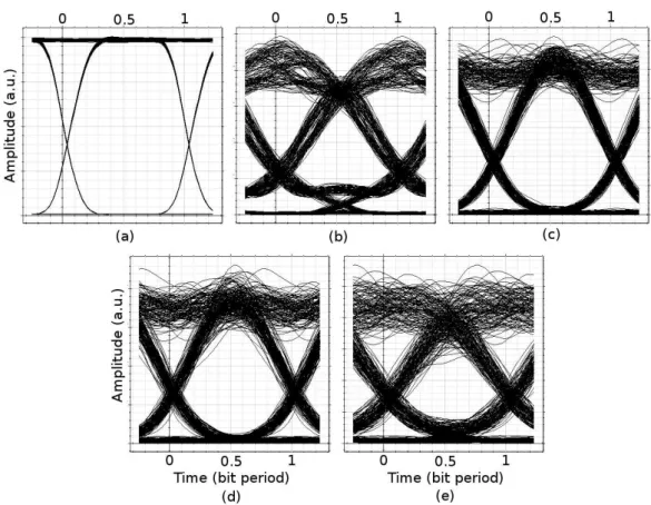
The 20 Gb/s eye-diagrams, for the simulation and experiment, are shown in Figures 5 and 6,
respectively. As the first dispersion compensation stage, DCM1, does not match the required
dispersion value, the performance degradation due to residual dispersion is notable. However, we
observe an improvement in performance after DCM2, that also compensated the residual dispersion,
and a more natural degradation from then on, due to the other impairments. Three of them, ASE
accumulation, electrical noise (the front end bandwidth, 40 GHz, is higher than necessary) and PMD
were expected. One must notice that the deleterious effects associated to PMD have not been
Fig. 5. 20 Gb/s simulated eye diagrams seen at: (a) back to back configuration; (b) after DCM1; (c) DCM2; (d) DCM3; and (e) DCM4.
Fig. 6. 20 Gb/s Experimental eye diagrams (horizontal scale of 10 ps/div, for each graph) seen at: (a) back to back configuration; (b) after DCM1; (c) DCM2; (d) DCM3; and (e) DCM4.
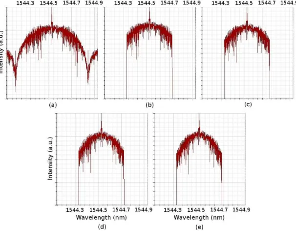
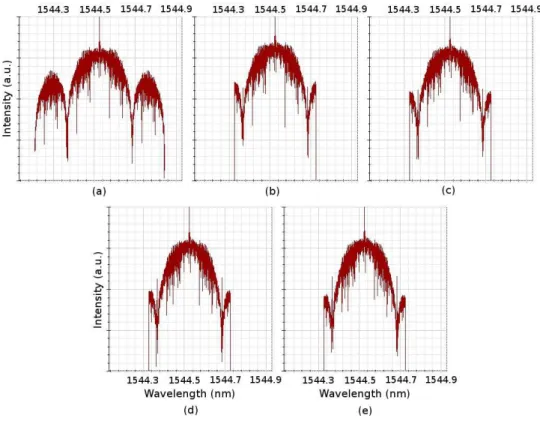
For evaluating the filter concatenation influence, we have carried out spectral simulations and
measurements, which are summarized in Figures 7 and 8, respectively. From Figure 7 we notice a loss
conclusion that even at 20 Gb/s the cascade of seven 50 GHz filters represent a limitation for the
system performance.
Fig. 7. 20 Gb/s simulated spectra seen at: (a) back to back configuration; (b) after DCM1; (c) DCM2; (d) DCM3; and (e) DCM4.
Fig. 8. Experimental optical spectrum of the 20 Gb/s signal in the back-to-back configuration and at the end of each fiber span (5 dB/div).
We also notice, in the experimental data, that the spectral narrowing may be slightly observed with
cross the filters and the one that does not cross them (the back to back transmission). Furthermore, for
the ASE accumulation effect, the modulated signal spectra after the 390 km path does not show a
significant Optical Signal-to-Noise Ratio (OSNR) penalty (OSNR ≈15 dB). One should note that the
excess of filtering along the optical path, if by one side limits the overall bandwidth, by the other side
acts to reduce the impact caused by ASE concatenation due a cascade of optical amplifiers, which has
been confirmed by our results.
Finally, we should remember the extra electrical bandwidth of the optical receiver, designed for
40 Gb/s measurements, which is likely to add extra electrical noise to the measured eye diagrams seen
in Figure 7. Considering that, it is reasonable to expect that a receiver designed for 20 Gb/s would
allow the reception of cleaner eye diagrams. Other effects, besides ASE accumulation, electrical noise
and PMD, such as nonlinear effects, could be further investigated in configurations with higher
optical power levels. For those used in the setup, we have not observed any strong impact caused by
fiber nonlinearities.
By using Equation (1) in the eye diagrams corresponding to the back-to-back and 390 km
transmission configurations, we have estimated the experimental and simulated eye-closure penalties
(ECP) as being around 1.1 dB and 0.8 dB, respectively. The ECP evaluation caused by filter
concatenation, for transmission rates varying from 2,5 to 100 Gb/s in different modulation formats,
has been studied by many authors [10]-[13]. One must remember that not only the cascade of filters
plays a role on the final penalty but it is combined with other degrading effect such as group delay
ripple and spectral misalignment caused by detuning of either, the WSSs, the laser source, or both.
For future reconfigurable networks, the ability to transmit through multiple 50 GHz reconfigurable
optical add/drop modules is becoming increasingly important yet challenging, which has motivated us
for evaluating a higher data rate (20 Gb/s) single-channel transmission through a setup configured for
transmitting multiple 10 Gb/s channels. Further studies with WDM transmission should, then,
considered the contribution of other associated constraining effects, such as signal cross talk caused
by leakage from adjacent channels.
Although a study made with the help of the bit error rate (BER) parameter would give us a
quantitative idea of the penalty caused by the group of deleterious effects, we believe that each effect
should be studied in an isolated configuration, first, in order to give us a better idea of its contribution
to the total penalty, which is the subject of future investigations
V. CONCLUSION
The transmission through nearly 400 km-long singlemode fiber of a NRZ OOK signal modulated at
20 Gb/s has been demonstrated. Although evaluated as a point-to-point link, the optical path
comprises four nodes with ROADMs designed for a DWDM network operation. According to the
results, we observe that the presence of accumulated effects, that would not allow the transmission of
large amount of filters (4 x WSS ROADMs, 7 x DCMs) and EDFAs (9 units). By contrary,
considering the possibility of including some forward error corrector technique, which could improve
the system performance, it is reasonable to affirm that the use of 20 Gb/s NRZ OOK may be a cost
effective strategy for network upgrades where the increase in capacity does not require a jump to
higher bit rates, which would imply in more complex and expensive technologies, such as coherent
detection with phase modulation formats. This way, the legacy of 10 Gb/s systems could be preserved
and reused, in a good choice for the network planning made by carriers that aim to keep in balance the
Capex.
Finally, one should notice that bit rates of 10, 40 and 100 Gb/s are standardized in
Telecommunications industry and the analysis presented in the paper is performed in a system with
20 Gb/s which is not a standard bit rate. However, the use of 20 Gb/s has increased in recent years,
mainly due to applications where modulation formats such DQPSK (and OFDM (Orthogonal
Frequency Division Multiplexing) are employed {14], [15].
ACKNOWLEDGMENT
This work has been supported by Funttel (Finep) and Fapesp (grant 06-04546-4).
REFERENCES
[1] A. Nag, M. Tornatore, and B. Mukherjee, “Optical Network Design wir Mixed Line Rates and Multiple Modulation Formats”, IEEE/OSA Journal of Lightwave Technology, V. 28, N. 4, pp. 466 – 475, 2010.
[2] G. Wellbrock and T.J. Xia, “The Road to 100 G Deployment”, IEEE Communications Magazine, V. 48, N. 3, pp. 14 – 16, 2010.
[3] J. Yu, X. Zhou, “Ultra High Capacity DWDM Transmission System for 100G and Beyond”, IEEE Communications Magazine, V. 48, N. 3, pp. 56 – 64, 2010.
[4] M. Seimetz, R. Freund, “Next Generation Optical Networks Based on Higher Order Modulation Formats, Coherent Receivers and Electronic Distortion Equalization”, Electrotechnik and Informationtechnik, V. 125, N. 7 & 8, pp. 284-289, 2008.
[5] OIF Forum, “100G Ultra Long Haul DWDM Framework Document”, http://www.oiforum.com/public/impagreements.html, published in 02/10.
[6] M. Batayneh, D. A. Schuploe, M. Hoffmann, A. Kirstaedter, and B. Mukherjee, “Optical Network Design for a Multiline-rate Carrier-grade Ethernet under Transmission-range constraints”, IEEE/OSA Journal of Lightwave Technology, V. 26, N. 9, pp. 1104-1118, 2008.
[7] I. Roudas, N. Antoniades, T. Otani, T. E. Stern, R. E. Wagner, and D. Q. Chowdhury, “Accurate Modeling of Optical Multiplexer/Demultiplexer Concatenation in Transparent Multiwavelength Optical Networks,” Journal of Lightwave Technology, V. 20, N. 6, pp. 921-936, 2002.
[8] J. D. Downie, and A. B. Ruffin, “Analysis of Signal Distortion and Crosstalk Penalties Induced by Optical Filters in Optical Networks,” Journal of Lightwave Technology, V. 21, N. 9, pp 1876-1886, 2003.
[10]B. Zhang, C. Malouin, G. Liao, S. Liu, P. Wang, H. Washburn, J. Yuan, and T. J. Schmidt, "1500-km Transmission of 100-Gb/s Coherent PM-QPSK with 10 Cascaded 50-GHz Wavelength Selective Switches," Conference on Lasers and Electro-Optics, OSA Technical Digest (CD) (Optical Society of America, 2010), paper CThC4.
[11]L. Zhu, M. Chen, Y. Zhang, S. Xie, “Impacts of cascaded filters with group delay ripples on 40-Gb/s WDM transmission system”, IEEE Photonics Technology Letters, V. 14, N. 11, pp. 1518-1520, 2002.
[12]P. Munoz, Penalty Evaluation Due to the Cascade and Frequency Misalignment of AW¨-Based Optical Add-Drop Multiplexers in 10 Gb/s Metro Core Ring Networks”, Fiber and Integrated Optics, V. 23, N. 2 & 3, pp. 59 – 65, 2004. [13]H. Bock, P. Leisching, A. Richter, D. Stoll, and G. Fischer, "System impact of cascaded optical add/drop multiplexers
based on tunable fiber Bragg gratings," Optical Fiber Communication Conference, OSA Technical Digest Series (Optical Society of America, 2000), paper WM29.
[14]Z. Liming, H. Yongqing, Z. Yangan, W. Gai, Z. Minglun, Z. Jinnan, Y.Xueguang ,“Parallel Prefix Network Based DQPSK Precoder for High-Speed Optical Transmission”, in Proceedings of International Forum on Information Technology and Applications (IFITA), 2010, V. 1, pp. 317 – 320, 2010.