Digital Control of Plasma Position
in Damavand Tokamak
M. Emami, A. R.Babazadeh, M. V. Roshan,M. Memarzadeh, and H. Habibi
PlasmaPhysisLab.,NFRC,AEOI,Iran
Reeivedon26June,2001
Plasmapositionontrolisoneoftheimportantissuesinthedesignandoperationoftokamakfusion
researhdevie. Sineatokamakisbasiallyaneletrialsystemonsistingofpowersupplies,oils,
plasmaandeddyurrents,amodelinwhihtheseomponentsaretreatedasaneletrialiruitsis
usedindesigningDamavandplasmapositionontrolsystem. Thismodelisusedforthesimulation
ofthedigital ontrol systemand itsparametershavebeenveriedexperimentally. Inthis paper,
theperformaneofahigh-speeddigitalontrolleraswellasasimulationstudyanditsappliation
totheDamavandtokamakisdisussed.
I Introdution
Tokamak is an eletrial systemonsisting of a
trans-former, plasma, eddy urrents, power supplies and
windings [1℄. The hanges in the plasma parameters
suhasdensity,temperatureandurrentreatefores,
whihmovestheplasmafromitsequilibrium position.
Plasma position feedbak ontrol in tokamaks viathe
appliation of lassial or modern ontrol theory has
beenstudiedextensively. Mosttokamakshaveadopted
analog ontrollers. The rapid development of digital
signal proessors (DSP) has inreased the speeds to
suh an extent whih digital ontrollers have beome
moreattrative[2℄-[6℄.
Thispaperdesribestheontrol systemsimulation
basedonahigh speedTexas-InstrumentDSPandits
appliationtotheplasmapositionontrolinDamavand
tokamak.
II Damavand Plasma Position
Model
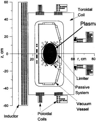
Damavand is a tokamak with an elongated plasma
ross-setion [7℄. The ross-setion of Damavand is
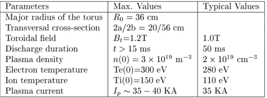
showninFig. 1anditsparametersaregiveninTable1.
Severalforesareatingontheplasma;thesearethe
ex-pansionforeduetotheplasmapressure,theforesdue
to the interations of magneti eld of vauum vessel
eddyurrentsandtheexternalmagnetieldwiththe
oils,vauumvesselandplasmathatform several
mu-tuallyinteratingeletriiruits,generatethesefores.
Theirappliedvoltages,resistane,andselfandmutual
indutaneandesribetheseiruits.
Parameters Max. Values TypialValues
Majorradiusofthetorus R
0
=36m
Transversalross-setion 2a/2b=20/56m
Toroidaleld B
t
=1.2T 1.0T
Dishargeduration t>15ms 50ms
Plasmadensity n(0)=310 19
m 3
210 19
m 3
Eletrontemperature Te(0)=300eV 280eV
Iontemperature Ti(0)=150eV 110eV
Plasmaurrent I
p
35 40KA 35KA
Table1. DAMAVANDParameters.
This systeman be represented by a simpleset of
rst-orderdierentialequationsfortheurrentsin the
iruitelements,augmentedbytheequationofmotion
fortheplasmaolumn[8℄,
d
dt
(MI)+RI=V (1)
mdv
dt =
X
(radialfores) (2)
Here Visthevetorofapplied voltages,Mis the
mu-tual indutanematrix, R is the (diagonal)matrixof
resistane forthe iruitelements, and I is the vetor
of urrents in the iruit elements. In Eq. (2), v is
the plasma olumn radialveloity and m is the mass
oftheplasmaolumn. Solvingtheaboveequationshas
derivedasimplelinearizedplasmapositionmodel
appli-ablenearequilibrium anditsLaplaetransformblok
diagram isshowninFig.2,where
H
(s)=G
p (s)I
(s)+G
1 (s)
p +
l
i
2
(s) (3)
In this equation s, is theLaplae transform operator,
I
(s)istheontroloilurrentLaplaetransform,
p is
thepoloidalbeta,l
i
istheplasmainternalindutane,
and G
p
(s)andG
1
(s)aretheplasmaposition and
dis-turbane Laplae transfer funtions whih have been
desribedindetailin ref. [4℄. Theparametersofthese
transferfuntions aretheomplexfuntions of: 1) the
eletrialharateristisandgeometryofthewindings,
vauum vessel, andinterating eletriiruits,and2)
plasma parameterssuh asurrent, major radius,and
minorradius. Thetwomostimportantparameters
dis-turbingtheplasmapositioninDamavandtokamakare
the plasma temperature (T) and density (n)
utua-tions, whih is inluded in the (
p +l
i
=2) parameter.
InthismodelontroloilurrentI
(t)hasbeenhosen
as ontrol input beause by varying this urrent the
magneti eld in theplasma areaan be easily
modi-Figure2. PlasmapositionLaplaetransformblok
diagram.
III Digital Control System
III.1 Introdution
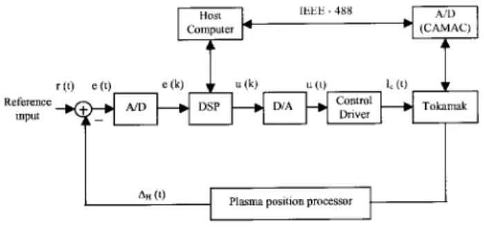
TheDamavanddigitalontrolsystemblokdiagram
isshown in Fig. 3. Theheart ofthis systemisaDSP
board,basedonahighspeed(12.5MIPS)TMS320C25
hip [9℄. It is used for the implementation of a
digi-talontrolalgorithm;itreeiveserrorsignale(k) and
generatestheontrol outputu(k);whihativatesthe
ontrol oil urrent. The TMS 320 family of
proes-sors is suitablefor implementation of digitallter [9℄,
[10℄.Theyhavethepowerforimplementingapoleand
zeroofadigitallterwith onlytwoinstrutions. Due
to xed-point representation of numbers by the DSP,
overow may our. Appropriatesaling beomes
im-portanttoavoidthisproblem. Theontroloilurrent
I
(t), is generated by a thyristor ontrol iruit with
the maximum time onstant of 200 s. Finally, the
plasmapositionwillbemonitoredandproessedusing
aplasmaposition-proessingunit. Theothertokamak
signals, whih are required for plasma modeling and
Figure3. Plasmapositiondigitalontrolsystem.
III.2 Digital Control System Analysis
Oneof the most widely used ontrol algorithms is
theproportional-integral-derivative(PID).The digital
PID ontrol algorithm implemented for this work is
used in the retangular approximation [11℄, T
(z 1) for
the integraloperation (1=s), and the bakward
dier-eneapproximation z 1
Tz
for thederivativeoperation
(s), where z = e sT
and T is the sampling period. It
shouldberealizedthataslongthesamplingfrequeny
is muh bigger than the system bandwidth the above
approximation holds. A digital PID ontroller
algo-rithmusingtheaboveapproximationanbewrittenin
theformofareursivediereneequation[9℄as
u(k)=u(k 1)+k
0
e(k)+k
1
e(k 1)+k
2
e(k 2): (4)
Wheree(k)andu(k)aretheontrollerinputand
out-putand, k 0 =k p 1+ T d T ; (5) k 1 =k p 1 2 T d T + T T i ; (6) k 2 =k p T d T : (7) WhereK p ,T i andT d
aretheproportionalgain,
in-tegral and derivative time onstant of the equivalent
analogPIDontroller. TheDSPanexeutethe
Equa-tion (4)within 1.3s and thetime required forother
tasks suh as exeuting the timing routine, interrupt
request handling and saling numbers is 13 s. The
output from this alulation u(k) anbe fairly noisy,
but theontroloil urrentdriveriruitwiththe200
stimeonstantatsasagoodlow-passlter.
TheA=D onverteris modeledasanidealimpulse
samplerombinedwith anite timedelayt
A=D to
a-ountfortheonversiontimeandisdesribedby
G (s)=K e t A=D s (8) Where K A=D
is theA=D gain. Finally, for simpliity
D=Aonverteris modeledasazero-order holddevie
[11℄anditsLaplaetransferfuntionisdesribedas
G
D=A
(s)=K
D=A 1 e
Ts
s
(9)
Where T andK
D=A
arethe samplingperiodand
on-vertergain,respetively.
III.3 Digital Controller Performane
The plasma position ontrol system of Damavand
tokamak based on a digital PID algorithm has been
simulatedbyomputerandisomparedwiththeDSP.
ThissimulationshowsthattheperformaneoftheDSP,
operating on 16Bit xed- point arithmeti is in lose
agreementwith the omputer,whih uses double
pre-ision oating- point data. This is obviously due to
thefatthatthesamplingrateismuhhigherthanthe
systembandwidth.
Theprimarymeasureoftheperformaneofthe
on-trollerisitsabilitytoontroltheplasmapositionwhen
it issubjetto disturbanes. Fig. 4showsthe plasma
position evolutionwith and withoutontrollerin a10
mm step-wise disturbane at the instant of time t=8
ms.
10
5
0
4
8
12
16
20
a
b
c
15
∆
H
(t) (m
m
)
Time (ms)
Figure 4. Plasma position ontrol system step response:
a) Digital ontroller, b)Analog ontrollerand )Without
ontroller.
Beauseofthesmallurrentinbuild-upphase(t<
8ms),theplasmapositionisverysensitivetothestray
magneti eld. Also, due to the iruit limitation at
low plasma urrent the plasma position measurement
is notveryaurate and the position is ontrolled by
preprogrammedmagnetield. Asitanbeseenfrom
Fig. 4busingtheanalogontroller,theplasmahasnot
returned tothe enter of thehamber(
H
=0) later
in the disharge. The reason is that the analog
on-troller gains were tuned for thesteady stateregion of
theplasmawhileforthelaststageinthedisharge,
be-auseofthehangesintheplasmaurrent,densityand
temperature, theparameters of theplasma model
gainsshouldhavebeenhangedaordinglyduring
dis-harge. This wasnot onvenientwith theanalog
on-trollerandhasbeenreplaedbydigitalontroller.
IV Conlusion
When model parameters are hanging due to the
plasma parameter variations, the ontroller gains
should be hanged during the disharge. Sine
ana-log ontroller was not exible it was replaed with
a digital ontroller. A digital ontrol system based
onTMS320C25 miroproessorhasbeendesignedand
built. Theresultsshowthedigitalsignalproessor
per-formane is satisfatory as long as the sampling
fre-queny is muh largerthan thebandwidth ofthe
sys-temwhihinludesDSPanditsassoiatediruitry
de-laytime, thyristor urrentontrol iruit,ontrol oil,
vauum vessel, andplasmaposition measurementunit
timeonstants.
Referenes
[1℄ J. Wesson, Tokamak, Oxford Siene Publiation,
(1987).
[2℄ J. R. Ulgum \Digital Feedbak ontrol for TEXT
Upgrade" Fusion Researh Center, Austin, Texas
FRCR#412(1992).
[3℄ J.B. Lister,F.Hofmann, J.M. Moret,M.J. Duth,D.
Y.Martin,A.Perez,andD.J.Ward,\TheControl of
TCVPlasmas"LRP518/95, July1996.
[4℄ M.Emami, H. C.Wood,A. Hirose, \Aontrollerfor
plasma motion in a tokamak based on model
esti-mation",IEEETransationsonIndustrialeletronis,
Vol.37,317(1990).
[5℄ Y.Mizuno,H.Muramatsu, T.AokiandT.Sometani,
\Feedbak position ontrol apparatus of tokamak
plasmahorizontalpositionwithadigital drive",
Ele-trialEngineeringinJapanVol.130,26(2000).
[6℄ A.Coutlis, J.N.Limebeer, J.P.Wainwright, J.B.
Lis-ter,andP.Vyas,\Frequenyresponseidentiationof
dynamisofatokamakplasma"IEEETransationson
ControlSystemTehnology,Vol.8,646(2000).
[7℄ R. Amrollahi, A.V. Bortnikov, N.N. Brevnov, Yu.V.
Gott,andV.A.Shurygin,\ExperimentalStudyofthe
Pre-Disruption in the Damavand Tokamak", Plasma
PhysisReports,Vol.23,561(1997).
[8℄ E.A. Lazarus, G.H. Neilson, \Solutions to the
toka-makiruitequationswithforebalaneforamassless
plasma",NulearFusion,Vol.27,383(1987).
[9℄ TMS320C2XFixed-PointUser'sGuide (Texas
Instru-mentSPRU014C).
[10℄ Hardware Interfaing to the TMS320C2X (Texas
In-strumentSPRA014B).
[11℄ DigitalControlSystems,C.Kuo,HRWseriesin